Table of Contents
Advertisement
Quick Links
Laser Lab Source
a division of Research Lab Source Corporation
contact@LaserLabSource.com
contact@LaserLabSource.com
800.887.5065
800.887.5065
www.LaserLabSource.com
phone: 800-887-5065
Operating Manual
C151 - Laser Diode Controller
250mA, Type-1 Pin Con guration
670 South Ferguson
Bozeman, MT 59718
Advertisement
Table of Contents

Subscribe to Our Youtube Channel
Related Manuals for RedWave Labs C151


Summary of Contents for RedWave Labs C151
- Page 1 Operating Manual C151 - Laser Diode Controller 250mA, Type-1 Pin Con guration contact@LaserLabSource.com contact@LaserLabSource.com 800.887.5065 800.887.5065 Laser Lab Source www.LaserLabSource.com 670 South Ferguson a division of Research Lab Source Corporation phone: 800-887-5065 Bozeman, MT 59718...
- Page 2 Operating manual Laser Controller C151...
-
Page 3: Table Of Contents
Laser Controller C151 www.redwavelabs.com Contents Introduction ..........................3 Absolute Maximum Ratings ......................4 Mechanical Information ........................ 4 Pin Layout ..........................4 Electrical Characteristics ....................... 5 Power Connector J6 ........................7 Control and Monitor Connector J4 ....................7 Control and Monitor Connector J5 (SMB) ..................8 Test Connector J1 ........................ -
Page 4: Introduction
SMB connector. Laser current has a hardware limit of 250 mA which cannot be exceeded in any case. Features Laser Controller C151 provides full control for semiconductor laser including laser diode control and integrated temperature control. Applications Spectroscopy, Laser, Precision Instrument, OEM applications... -
Page 5: Absolute Maximum Ratings
Laser Controller C151 www.redwavelabs.com Absolute Maximum Ratings Symbol Parameter Ratings Unit Supply positive voltage / Laser driver and TEC +12±10% Supply positive voltage / Separate TEC rail +5;+10%;-0% Supply negative voltage / Laser driver and -12±10% Operational Temperature -40 to 85... -
Page 6: Electrical Characteristics
Laser Controller C151 www.redwavelabs.com Electrical Characteristics Parameter Comments Value Unit POWER Supply positive voltage Positive supply voltage for laser driver, all / Laser driver and control circuits and TEC. 2 A minimum is 12+/-10% required for single positive power supply Positive supply voltage for TEC only. - Page 7 Laser Controller C151 www.redwavelabs.com Parameter Comments Value Unit Laser current -3 dB modulation bandwidth Additional modulation capabilities on top Laser current TTL of the analog modulation. Fast ON/OFF modulation rise/fall time switches 0-10 (for custom version Laser current monitor Monitor averaged laser current...
-
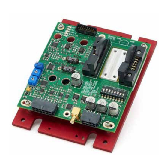
Page 8: Power Connector J6
Power connector J6 (pin assignment is on left) is Molex Micro-Fit p/n 43045-0800. Mating connector is Molex Micro-Fit p/n 43025-0800 with crimp pins Molex p/n 43030-0009. Mating connector and necessary number of crimp pins are included with C151 Laser controller. Molex suggested crimping tool p/n 63819-0000 which can be purchased from Digikey Inc (www.digikey.com) -
Page 9: Control And Monitor Connector J5 (Smb)
43045-1200. Mating connector is Molex Micro-Fit p/n 43025-1200 with crimp pins Molex p/n 43030-0009 . Mating connector and necessary number of crimp pins are included with C151 Laser controller. Molex suggested crimping tool p/n 63819-0000 which can be purchased from Digikey Inc (www.digikey.com) -
Page 10: Dip Switchs1
Molex Milli-Grid p/n 87568-1694 for ribbon cable. C151 comes without Milli-Grid mating connector. Customized connector arrangement can be used for the remote control of the switch S1. RedWave Labs can advised on the specific applications when required. DIP SwitchS1 S1 can be remotely controlled through J1 except for the TEC power selection (POSITION 8 in table below). -
Page 11: Status Led
Laser Controller C151 www.redwavelabs.com Status LED Status LEDs are used for fast visual assessment of the C151 status. LEDs are located close to test connector J1. Default LED color is red; this can varied in customized versions. LED # Abbreviation... -
Page 12: Pi Control
PI Control C151 has 2 options to control the temperature feedback loop: Internal and External. Internal PI control covers the vast majority of systems and the P and I control potentiometers can be adjusted to obtain the optimal PI. External PI control can be used if the user has a digital PID implementation elsewhere and connected to the Pin 3 of J4. -
Page 13: External Connections And Cables
Installation We recommend a first time use of the C151 with a high power load resistor (at least 10W rating) as TEC load and Laser Diode load. These load should connected to the corresponding pins of J1. Such a set-up will enable a system check before connecting to the laser temperature controller system and risking potential damages.
Need help?
Do you have a question about the C151 and is the answer not in the manual?
Questions and answers