Table of Contents
Advertisement
Quick Links
Advertisement
Table of Contents

Related Manuals for RedWave Labs C158


Summary of Contents for RedWave Labs C158
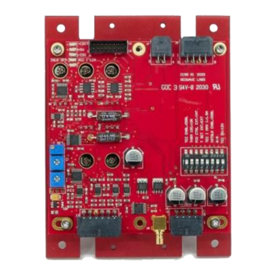
- Page 1 Operating manual Laser Controller C158...
-
Page 2: Table Of Contents
Laser Controller C158 www.redwavelabs.com Contents Introduction ..........................3 Absolute Maximum Ratings ......................4 Mechanical Information ........................ 4 Electrical Characteristics ....................... 5 Power Connector J6 ........................7 Laser TEC Connector J7 ....................... 7 Laser Connector J8 ........................8 Control and Monitor Connector J4 ....................8 Control and Monitor Connector J5 (SMB) .................. -
Page 3: Introduction
TTL compatible switching provided via SMB connector. Laser current has a hardware limit of 250 mA which cannot be exceeded in any case. Features Laser Controller C158 provides full control for semiconductor laser including laser diode control and integrated temperature control. Applications... -
Page 4: Absolute Maximum Ratings
Laser Controller C158 www.redwavelabs.com Absolute Maximum Ratings Symbol Parameter Ratings Unit Supply positive voltage / Laser driver and TEC +12±10% Volt Supply positive voltage / Separate TEC rail +5;+10%;-0% Volt Supply negative voltage / Laser driver and -12±10% Volt Operational Temperature... -
Page 5: Electrical Characteristics
Laser Controller C158 www.redwavelabs.com Electrical Characteristics Parameter Comments Value Unit POWER Supply positive voltage Positive supply voltage for laser driver, all / Laser driver and control circuits and TEC. 2 A minimum is 12 ± 10% required for single positive power supply Positive supply voltage for TEC only. - Page 6 Laser Controller C158 www.redwavelabs.com Parameter Comments Value Unit Additional modulation capabilities on top Laser current TTL of the analog modulation. Fast ON/OFF modulation rise/fall time switches 0-10 (for custom version Laser current monitor Monitor averaged laser current less than 10V...
-
Page 7: Power Connector J6
Laser Controller C158 www.redwavelabs.com Parameter Comments Value Unit Integrated Azimuth Electronics 14 pin connector with heat sink. NEL DFB laser Laser connector pinout. Can be replaced with optional DB15 connector. Test connector: can be used for remote Test connector J1 control of the driver. -
Page 8: Laser Connector J8
Power connector J7 (pin assignment is on left) is Molex Micro-Fit p/n 43045-0400. Mating connector is Molex Micro-Fit p/n 43025-0400 with crimp pins Molex p/n 43030-0009. Mating connector and necessary number of crimp pins are included with C158 Laser controller. Molex suggested crimping tool p/n 63819-0000 which can be purchased from Digikey Inc (www.digikey.com) -
Page 9: Control And Monitor Connector J5 (Smb)
Laser Controller C158 www.redwavelabs.com PIN# Abbreviation Name Description TEC current limit 0V – normal operation; +5V if current limit (any side) is LIMIT_I_FAULT error reached. Control and Monitor Ground connection. Must not be used Ground for power ground. Actual temperature T_ACTUAL_MON Buffered output of the voltage across the thermistor. -
Page 10: Dip Switchs1
TEC_POWER_CONTROL Power Supply Status LED Status LEDs are used for fast visual assessment of the C158 status. LEDs are located close to test connector J1. Default LED color is red; this can varied in customized versions. LED # Abbreviation Name... -
Page 11: Temperature Set Point
Temperature Set Point C158 has 2 options to control temperature set point. These options are:i) internal set point with the 11-turn potentiometer located on the opposite side of laser connector ; ii) external voltage applied to the Pin 7 of the J4 connector. -
Page 12: Pi Control
PI Control C158 has 2 options to control the temperature feedback loop: Internal and External. Internal PI control covers the vast majority of systems and the P and I control potentiometers can be adjusted to obtain the optimal PI. External PI control can be used if the user has a digital PID implementation elsewhere and connected to the Pin 3 of J4. -
Page 13: Installation
Return procedure Customer must obtain a valid RMA number by contacting RedWave Labs prior to the return. In all cases the customer is responsible for duty fees incurred on all received shipments and on all international returns for both warranty and non- warranty items;...
Need help?
Do you have a question about the C158 and is the answer not in the manual?
Questions and answers