Table of Contents
Advertisement
Quick Links
Laser Lab Source
a division of Research Lab Source Corporation
250mA, for Nanoplus Butterfly Lasers
contact@LaserLabSource.com
contact@LaserLabSource.com
800.887.5065
800.887.5065
www.LaserLabSource.com
phone: 800-887-5065
Operating Manual
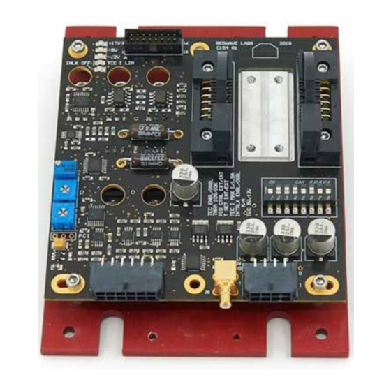
C154 - Laser Diode Controller
670 South Ferguson
Bozeman, MT 59718
Advertisement
Table of Contents

Subscribe to Our Youtube Channel
Related Manuals for RedWave Labs C154


Summary of Contents for RedWave Labs C154
- Page 1 Operating Manual C154 - Laser Diode Controller 250mA, for Nanoplus Butterfly Lasers contact@LaserLabSource.com contact@LaserLabSource.com 800.887.5065 800.887.5065 Laser Lab Source www.LaserLabSource.com 670 South Ferguson a division of Research Lab Source Corporation phone: 800-887-5065 Bozeman, MT 59718...
- Page 2 Operating manual Laser Controller C154...
-
Page 3: Table Of Contents
Laser Controller C154 www.redwavelabs.com Contents Introduction ..........................3 Absolute Maximum Ratings ......................4 Mechanical Information ........................ 4 Pin Layout ..........................4 Electrical Characteristics ....................... 5 Power Connector J6 ........................7 Control and Monitor Connector J4 ....................7 Control and Monitor Connector J5 (SMB) ..................8 Test Connector J1 ........................ -
Page 4: Introduction
Laser current has a hardware limit of 250 mA which cannot be exceeded in any case. Custom version has current limit set by customer request. In this case name will reflect maximum current limit like C154-70. 70 stands for maximum current. -
Page 5: Absolute Maximum Ratings
Laser Controller C154 www.redwavelabs.com Absolute Maximum Ratings Symbol Parameter Ratings Unit Supply positive voltage / Laser driver and TEC +12±10% Volt Supply positive voltage / Separate TEC rail +5;+10%;-0% Volt Supply negative voltage / Laser driver and -12±10% Volt Operational Temperature... -
Page 6: Electrical Characteristics
Laser Controller C154 www.redwavelabs.com Electrical Characteristics Parameter Comments Value Unit POWER Supply positive voltage Positive supply voltage for laser driver, all / Laser driver and control circuits and TEC. 2 A minimum is 12 ±10% required for single positive power supply Positive supply voltage for TEC only. - Page 7 Laser Controller C154 www.redwavelabs.com Parameter Comments Value Unit Laser current -3 dB modulation bandwidth Additional modulation capabilities on top Laser current TTL of the analog modulation. Fast ON/OFF modulation rise/fall time switches 0-10 (for custom version Laser current monitor Monitor averaged laser current...
-
Page 8: Power Connector J6
Power connector J6 (pin assignment is on left) is Molex Micro-Fit p/n 43045-0800. Mating connector is Molex Micro-Fit p/n 43025-0800 with crimp pins Molex p/n 43030-0009. Mating connector and necessary number of crimp pins are included with C154 Laser controller. Molex suggested crimping tool p/n 63819-0000 which can be purchased from Digikey Inc (www.digikey.com) -
Page 9: Control And Monitor Connector J5 (Smb)
43045-1200. Mating connector is Molex Micro-Fit p/n 43025-1200 with crimp pins Molex p/n 43030-0009 . Mating connector and necessary number of crimp pins are included with C154 Laser controller. Molex suggested crimping tool p/n 63819-0000 which can be purchased from Digikey Inc (www.digikey.com) -
Page 10: Dip Switchs1
Molex Milli-Grid p/n 87568-1694 for ribbon cable. C154 comes without Milli-Grid mating connector. Customized connector arrangement can be used for the remote control of the switch S1. RedWave Labs can advised on the specific applications when required. DIP SwitchS1 S1 can be remotely controlled through J1 except for the TEC power selection (POSITION 8 in table below). -
Page 11: Status Led
Laser Controller C154 www.redwavelabs.com Status LED Status LEDs are used for fast visual assessment of the C154 status. LEDs are located close to test connector J1. Default LED color is red; this can varied in customized versions. LED # Abbreviation... -
Page 12: Pi Control
Laser Controller C154 www.redwavelabs.com correct temperature. For example V =2.500 V for T=25 C using 10K thermistor settings and using the 10K thermistor as the temperature measurement element. Note: This voltage is different from T voltage (see above Temperature Set Point). -
Page 13: External Connections And Cables
Return procedure Customer must obtain a valid RMA number by contacting RedWave Labs prior to the return. In all cases the customer is responsible for duty fees incurred on all received shipments and on all international returns for both warranty and non- warranty items;...
Need help?
Do you have a question about the C154 and is the answer not in the manual?
Questions and answers