Advertisement
Quick Links
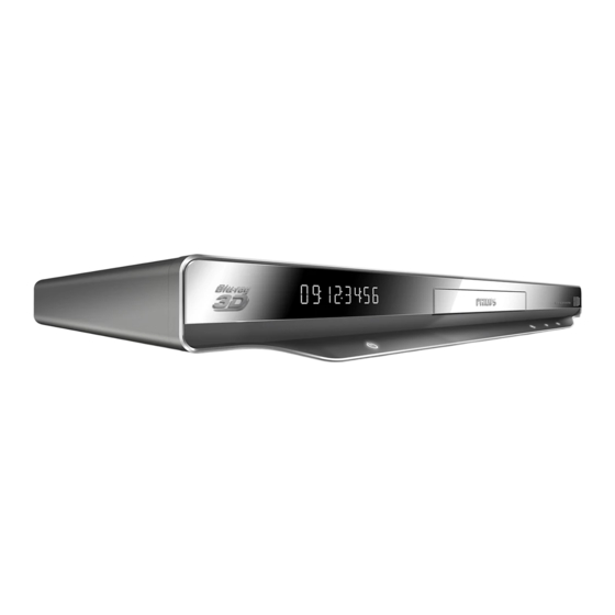
Blu-ray Disc Player
TABLE OF CONTENTS
Location of PCB Boards & version variation & repair scenario matrix..................... 1-1
Production Specifications ...............................................................................................1-2
Remote control ...............................................................................................................1-4
Brife guide ......................................................................................................................1-
Safety Instruction, Warning & Notes...............................................................................1-
Mechanical and Dismantling Instructions .......................................................................2-1
Software Version & Upgrades.........................................................................................3-1
Trouble Shooting Chart .....................................................................................................-1
Set Block & Wiring Diagrams ............................................................................5-1
Electrical Diagrams and PCB layouts ................................................................6-1
Set Mechanical Exploded view ....................................................................................... -1
Revision List ...................................................................................................................
©
Copyright 2010 Philips Consumer Electronics B.V. Eindhoven, The Netherlands
All rights reserved. No part of this publication may be reproduced, stored in a retrieval system or
transmitted, in any form or by any means, electronic, mechanical, photocopying, or otherwise without
the prior permission of Philips.
Published by Helen-RY 1109 Service Audio Printed in The Netherlands Subject to modification
Version 1.0
Version 0.0
BDP7600/05/12/51/93
Page
5
10
4
7
-1
8
CLASS 1
LASER PRODUCT
©
313978535630
GB
GB
Advertisement


Need help?
Do you have a question about the BDP7600/51 and is the answer not in the manual?
Questions and answers