
Subscribe to Our Youtube Channel
Related Manuals for Thermal Dynamics iCNC


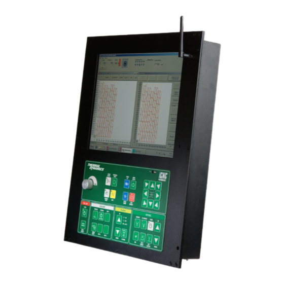
Summary of Contents for Thermal Dynamics iCNC
- Page 1 ® INPUT VOLTAGE iCNC PERFORMANCE CNC CONTROLLER Operator Manual Revision: AB Issue Date: February, 2016 Manual No.: 0-5399 Thermal-Dynamics.com www.TechnicalBooksPDF.com...
- Page 2 ® WE APPRECIATE YOUR BUSINESS! Congratulations on your new Thermal Dynamics product. We are proud to have you as our customer and will strive to provide you with the best service and reliability in the industry. This product is backed by our extensive warranty and world-wide service network. To locate your nearest distributor or service agency call 1-800-752-7622, or visit us on the web at www.thermal-...
- Page 3 Publication Date: August 19, 2015 Revision Date: February, 2016 Record the following information for Warranty purposes: Where Purchased: ___________________________________ Purchase Date:______________________________________ iCNC Performance Serial #:_____________________________ www.TechnicalBooksPDF.com...
- Page 4 Be sure this information reaches the operator. You can get extra copies through your supplier. CAUTION These INSTRUCTIONS are for experienced operators. If you are not fully familiar with the principles of operation and safe practices for arc welding and cutting equipment, we urge you to read our booklet, “Precautions and Safe Practices for Arc Welding, Cutting, and Gouging,”...
- Page 5 ASSUREZ-VOUS QUE CETTE INFORMATION EST DISTRIBUÉE À L’OPÉRATEUR. VOUS POUVEZ OBTENIR DES COPIES SUPPLÉMENTAIRES CHEZ VOTRE FOURNISSEUR. ATTENTION Les INSTRUCTIONS suivantes sont destinées aux opérateurs qualifiés seulement. Si vous n’avez pas une connaissance approfondie des principes de fonctionnement et des règles de sécurité pour le soudage à l’arc et l’équipement de coupage, nous vous suggérons de lire notre brochure «...
- Page 6 This Page Intentionally Blank www.TechnicalBooksPDF.com...
- Page 7 2004/108/EC The Electromagnetic Compatibility Directive hereby declare that Equipment: Plasma Cutting CNC Controller Model Name/Number: iCNC Performance Market Release Date: August 19, 2015 is in conformity with the applicable requirements of the following harmonized standards Conforms to requirements of IEC 61326-1:2012...
- Page 8 WARNING This Class A equipment is not intended for use in residential locations where the electrical power is provided by the public low-voltage supply system. There may be potential difficul- ties in ensuring electromagnetic compatibility in those locations, due to conducted as well as radiated disturbances.
-
Page 9: Table Of Contents
TABLE OF CONTENTS SECTION 1: SAFETY ..................1-1 1.01 Safety Precautions - ENGLISH ................ 1-1 1.02 Précautions de sécurité - FRENCH CANADIAN ..........1-6 SECTION 2: SPECIFICATIONS ................2-1 System Description ..................2-1 Specification ....................2-1 SECTION 3: OPERATION ................... 3-1 Overview Main Screen .................. - Page 10 TABLE OF CONTENTS SECTION 6: MAINTENANCE AND TROUBLESHOOTING ..........6-1 Maintenance ....................6-1 Cut Quality ...................... 6-1 Oxy fuel cutting quality ................... 6-2 Troubleshooting ....................6-4 Replacement parts ..................6-6 STATEMENT OF WARRANTY ............INSIDE REAR COVER www.TechnicalBooksPDF.com...
-
Page 11: Section 1: Safety
PERFORMANCE SECTION 1: SAFETY 1.01 Safety Precautions - ENGLISH WARNING: These Safety Precautions are for your protection. They summarize precautionary informa- tion from the references listed in Additional Safety Information section. Before performing any instal- lation or operating procedures, be sure to read and follow the safety precautions listed below as well as all other manuals, material safety data sheets, labels, etc. - Page 12 PERFORMANCE ELECTRICAL SHOCK -- Contact with live electrical parts and ground can cause severe injury or death. DO NOT use AC welding current in damp areas, if movement is confined, or if there is danger of falling. 1. Be sure the power source frame (chassis) is connected to the ground system of the input power.
- Page 13 PERFORMANCE CYLINDER HANDLING -- Cylinders, if mishandled, can rupture and violently release gas. Sudden rupture of cylinder, valve, or relief device can injure or kill. Therefore: 1. Use the proper gas for the process and use the proper pressure reducing regulator designed to operate from the compressed gas cylinder.
- Page 14 PERFORMANCE Meaning of symbols - As used throughout this manual: Means Attention! Be Alert! Your safety is involved. Means immediate hazards which, if not avoided, will result in immediate, serious DANGER personal injury or loss of life. CAUTION Means potential hazards which could result in personal injury or loss of life.
- Page 15 PERFORMANCE This Page Intentionally Blank Manual 0-5399 SAFETY INSTRUCTIONS www.TechnicalBooksPDF.com...
-
Page 16: Précautions De Sécurité - French Canadian
PERFORMANCE 1.02 Précautions de sécurité - FRENCH CANADIAN AVERTISSEMENT : Ces règles de sécurité ont pour but d’assurer votre protection. Ils récapitulent les informations de précaution provenant des références dans la section des Informations de sécurité supplémentaires. Avant de procéder à l’installation ou d’utiliser l’unité, assurez-vous de lire et de suivre les précautions de sécurité... - Page 17 PERFORMANCE 5. Assurez-vous de ne pas excéder la capacité de l’équipement. Par exemple, un câble de soudage surchargé peut surchauffer et provoquer un incendie. 6. Une fois les opérations terminées, inspectez l’aire de travail pour assurer qu’aucune étincelle ou projection de métal incandescent ne risque de provoquer un incendie ultérieurement.
- Page 18 PERFORMANCE LES VAPEURS ET LES GAZ -- peuvent causer un malaise ou des dommages corporels, plus par- ticulièrement dans les espaces restreints. Ne respirez pas les vapeurs et les gaz. Le gaz de protec- tion risque de causer l’asphyxie.
- Page 19 PERFORMANCE 4. N’utilisez pas l’équipement de façon abusive. Gardez l’équipement à l’écart de toute source de chaleur, notamment des fours, de l’humidité, des flaques d’eau, de l’huile ou de la graisse, des atmosphères corrosives et des intempéries. 5. Laissez en place tous les dispositifs de sécurité et tous les panneaux de la console et maintenez-les en bon état.
- Page 20 PERFORMANCE MISE EN GARDE L’équipement pourrait basculer s’il est placé sur une surface dont la pente dépasse 15°. Vous pourriez vous blesser ou endommager l’équipement de façon importante. 15° Art# A-12726 MISE EN GARDE Soulevez à l’aide de la méthode et des points d’attache illustrés afin d’éviter de vous blesser ou d’endommager...
-
Page 21: Section 2: Specifications
System Description iCNC Performance is intended for shape cutting control. iCNC Performance has motion control, I/O, user interface and an optional plasma height control built all in one package. These units are not field repairable. Unauthorized opening of the unit will void the warranty. - Page 22 PERFORMANCE This Page Intentionally Blank SPECIFICATIONS Manual 0-5399 www.TechnicalBooksPDF.com...
-
Page 23: Section 3: Operation
PERFORMANCE SECTION 3: OPERATION Overview Main Screen The main screen is divided into three parts. • Info (Systems Status) • Promotion Cut – Next Job Preview • Current Job Manual 0-5399 OPERATION www.TechnicalBooksPDF.com... - Page 24 PERFORMANCE 3.1.1 Info (System Status) This is located on top of the screen. The info screen shows system information and is used for diagnostics and troubleshooting. • Speed IPM (or metric) indicates machine speed. • X & Y readouts indicate absolute position of the cutting tool.
- Page 25 PERFORMANCE Opens the process selection window. Selecting the Program button will open the selection to Macro Shape Library or download in ProMotion Nest. Plate button open the plate alignment window. Zoom button opens the zoom window. This lets you take a closer look at the parts.
- Page 26 PERFORMANCE 3.1.3 Current Job Located on the right hand side of the screen, the Current Job window displays the current job being cut with real time tracking. Normally grayed out. Activated when a cutting program is stopped by pressing the Torch On/Off or the Stop–Backup button located on the front panel of the controller.
- Page 27 PERFORMANCE The Cut again box allows the opportunity to suspend and save a current job and restart a saved job. • Cancel – Cancel any selected functions under the Cut again box • Show new start point – Selecting this function allows the user to point the pierce point that will start the cut. Parts before the selection will be ignored.
-
Page 28: Process Selection / Plasma And Gas
PERFORMANCE Process Selection / Plasma and Gas In this window you can select the process used to cut or edit existing processes. 1. Clicking Gas will open the gas parameter set selection. 2. Clicking Plasma will open the plasma process window. - Page 29 PERFORMANCE 3.2.1 Plasma Setup Definition of areas under the Cut Process Tab are shown on the bottom of the Thermal Screen 1. Use the drop down boxes to select the material and thickness to be cut. 2. The available cut processes for the selected material and thickness will be displayed along with information indicating which process is “B”...
-
Page 30: Front Panel Buttons
PERFORMANCE Front Panel Buttons The iCNC Performance operating control panel is located below the LCD graphics screen. Most machine motion and cutting functions are initiated using this operating control panel. 3.3.1 Speed Potentiometer Turning the potentiometer counter clockwise decreases the actual speed in comparison with the programmed speed. This potentiometer is only used in special cases, such as temporarily slowing down the cutting speed. - Page 31 PERFORMANCE 3.3.3 Manual Mode Button Pressing the MANUAL MODE button activates the capability to jog and reposition the machine. CAUTION Pressing the MANUAL MODE button again will turn off the manual mode and will ask if you want to return the machine to the last known parked position.
- Page 32 PERFORMANCE 3.3.8 Speed Up & Speed Down Buttons Short pushes increase or decrease the actual and set speed in small steps. Long lasting pushes change the speeds at a faster rate. The pushbuttons will illuminate during automatic corner acceleration and deceleration respectively.
-
Page 33: On/Off Button Descriptions And Functions
PERFORMANCE ON/OFF Button Descriptions and Functions CAUTION Most buttons have 2 functions, different color LEDs indicate the state. Pressing a button will toggle the function ON/OFF and keeping the button pressed in for 3 seconds will toggle the function to AUTO. Green LED indicates ON state and orange indicates AUTO state. -
Page 34: Plasma Button Descriptions And Functions
PERFORMANCE 3.5.3 AUX 1-3 On/Off/Auto • ON position will activate the auxiliary device, example water table. • AUTO position will activate the auxiliary device, example water table when a cutting program is active. • OFF position will turn off the auxiliary device, example water table). -
Page 35: Oxyfuel Button Descriptions And Functions
PERFORMANCE Oxyfuel Button Descriptions and Functions CAUTION Most buttons have 2 functions and the different color LEDs indicate the state. Pressing a button will toggle the function ON/OFF and keeping the button pressed in for 3 seconds will toggle the function to AUTO. Green LED indicates ON state and orange indicates AUTO state. -
Page 36: Starting Procedure
Switch on the system by pressing the power button located on the far left hand side of the unit for 5 seconds. When power is applied, the iCNC Performance will take approximately 1-2 minutes to go through internal diagnostics and fully boot up. After full power up, the Promotion Work Screen displaying Promotion Cut, Next Job Preview and Current Job along with Info (System Status) will be displayed. -
Page 37: Homing Procedure
Homing Procedure During initial power up, the iCNC Performance may display a Start homing procedure dialog box. If you select Yes, the machine will automatically locate the absolute zero home location. As a default, this is normally set at the bottom left corner of the cutting table, however this is selectable in the set-up parameters. - Page 38 Program Zeros iCNC Performance will save the coordinates for last 5 program starts relative to the absolute 0.0 position. You can choose the wanted program zero point from the drop down list and click drive to.
-
Page 39: How To Proceed When Something Happens
PERFORMANCE Parameter Set (Plasma) If selected in the Advanced Setup screen, the material type, thickness and tool used will appear here to guide the operator on the current parameter selection. NOTE! Additional delays or adjustable time dialog boxes may appear, depend- ing on how the controller has been set-up by an OEM or installer. - Page 40 PERFORMANCE 3.12.3 If the Cutting Fails If the cutting is terminated e.g. for too high speed: 1. Stop the movement and cutting by pressing TORCH ON/OFF or STOP BACKUP. 2. Adjust the speed slower with the SPEED knob if necessary.
- Page 41 PERFORMANCE 3.12.6 Trial Run, No Cutting This will allow faster set up to reposition a program on the plate, eliminating the need to reposition the plate. 1. Call up the wanted program on the Next JOB screen. 2. Bring the cutting program to CURRENT JOB window by clicking the Next Job Preview button 3.
-
Page 42: Advanced Process Selection Features
PERFORMANCE 3.14 Advanced Process Selection Features The process selection screen allows the operator the flexibility to change more parameters if needed. Process selection has tabs contain- ing different settings. You can get to the different settings by clicking either Settings (1) or Edit (2) when a process is selected. You can also build a material database of common materials being cut, and save different speeds and kerf values within each profile and for each process you edit. - Page 43 PERFORMANCE NOTE! Parameter windows may alternate based on the machine setup. See installation/service manual about setting delays and names. Pictures for reference only. Language Select the language used in process selection. Tool Locations If a laser pointer is installed on the machine, it is best to define tool locations relative to the laser pointer. This way you can position and set the zero point using the laser pointer and the system knows the location of all additional tools and can automatically handle them while cutting a program.
- Page 44 PERFORMANCE SD1, SD2 and SD3 These delays are typically not used when using plasma as the marking device, but are fully available and programmable. Typically used for starting the Initial Height Sensing and igniting the marker. Move Delay Delay before motion will begin.
- Page 45 Process Database The iCNC Performance has a unique feature that allows building a database for specific cutting parameters based on material, thickness, gas and tool. Based on material, thickness and tool selected, the cutting parameters can change automatically for kerf, cutting speeds and other parameters.
- Page 46 PERFORMANCE 3. Set your parameters Speed This is the machine cutting speed. This setting duplicates the cutting speed setting in folder 1 Parameters. Changing one, changes the other. Kerf The process kerf. Creep speed The initial speed of the cutting torch will immediately be activated after the start command is given. The duration of this speed is determined by the setting of the Creep Time parameter.
- Page 47 PERFORMANCE 3.14.5 Cutting Parameter Delays NOTE! Parameter windows may alternate based on the machine setup. If a delay is not shown it is set as hidden. Delays can also be locked so that editing the time value is not pos- sible .
- Page 48 PERFORMANCE Examples: SD4 starts the event timing sequence for piercing up/down routine. The initial values for piercing up time - stay up time and piercing down time are set to 1 second for this example. 1. Cutting oxygen turned on as torch raises to piercing height. Set SD4 value from .1-.9 seconds.
-
Page 49: Section 4: Ihc
PERFORMANCE SECTION 4: iHC Pierce/Cut Sequense Pierce/Cut Flow Sequence: 1. IHS Start activated torch starts to find the plate. 2. Torch reaches slowdown height and starts to move slowly. 3. Torch touches the plate. 4. Torch moves to ignition height and gives command to start the plasma. -
Page 50: Ihc User Interface
The iHC can be almost invisible to the operator because the Height Control Parameters can come from the cutting program or fully automati- cally from the Material/Thickness/Tool parameter sets. This window does not hide any controls normally used to run the iCNC Performance it can be viewed at all times. - Page 51 PERFORMANCE • The “UP” and “DOWN” buttons can be used to move the torch in manual mode. • IHS Test button causes the torch to drive down to find a plate. This feature can be used to test that the iHC plate sensing works properly.
-
Page 52: Main Settings
PERFORMANCE Main Settings Clicking the “Setup” button will open the Setup Main screen under the iHC Info Bar. This screen • Continuously displays the actual Arc Voltage and the height of the torch from the plate (the height where the plate was sensed at the time of pierce). -
Page 53: System Setup & Diagnostic Menus
PERFORMANCE System Setup & Diagnostic Menus 4.4.2 Marking Tab • Arc Voltage, used when marking • Cut Height, used when marking • Ignition Height, used when marking • Pierce Height, used when marking • Pierce Height Time, used when marking •... - Page 54 PERFORMANCE 4.4.3 Advanced Tab Provides the option for more detailed control of the system behavior. Default Values Imperial Metric High Jog Speed 59,06 IPM 1500 mm/min Low Jog Speed 11,81 IPM 300 mm/min Adjust Speed 118,11 IPM 3000 mm/min...
- Page 55 PERFORMANCE 4.4.4 I/O Bits Tab This tab displays the status of various system signals for diagnostic purposes. I/O bits are separated to inputs (signals that come from other devices to iHC) and outputs (signals that go from the iHC to other devices).
- Page 56 PERFORMANCE Outputs 14. System Error (Inverted) can be connected to CNC controllers external stop 15. Optional reserved for future use 16. Sense Relay 24VDC Output for voltage divider board. 17. IHS Active outbit which is active form the time IHS Start turns active until Ignition Height has been reached.
- Page 57 PERFORMANCE 4.4.6 Installation Tab These parameters are password protected. Some parameters are the same as on the Advanced Tab. • Encoder pulse edges per meter Determined by the type of encoder and the threaded shaft of the lifter. • Full Speed The maximum speed of the lifter. Full Speed is used above Slow Down Height.
- Page 58 PERFORMANCE 4.4.7 Parameter Limits Parameter name Default Adjust speed 3000mm/min 18000 Collision recovery delay Collision retract height Cut height Cut height AVC delay 0,2s Manual acceleration 0.3g Manual deceleration 0.3g Encoder pulses per meter 500000p/m 2^31 Find plate speed...
-
Page 59: Section 5: Nest
PERFORMANCE SECTION 5: NEST ProMotion Nest ® ProMotion® Nest is software which converts CAD pictures (DXF format) to cutting programs. It is also possible to modify existing cutting programs (EIA, ESSI or CNC-2 format). Basics ® When ProMotion Nest loads a CAD picture it adds cutting technology (kerf side, piercing points, cutting order, etc.) to shapes auto- matically. - Page 60 PERFORMANCE Menu bar The Menu Bar lies just below the Title Bar and allows you to choose one of the following: File Menu View Menu Tools Menu Options Menu Registration Menu Help Menu Toolbar The Toolbar lies just below the menu bar. The Toolbar contains buttons for quick access to most of the important tools of ProMotion®...
-
Page 61: Toolbar
PERFORMANCE Toolbar ProMotion® Nest toolbar looks like this: Here is a brief description of each tool: Send to cutting Sends the current nesting to ProMotion® Cut and activates it. New Plate Creates a new plate. See more info at topic New Plate under File Menu File open Opens a CNC or a DXF file. -
Page 62: Toolbar Functions
Send to Cutting When the nesting is ready for cutting click this button to send it to ProMotion® Cut. NOTE! This tool works only on ProMotion® iCNC controllers. 5.3.2 New Plate When you activate this tool a window appears asking the length and width of the new plate. - Page 63 PERFORMANCE If you load a file that is in DXF-format and that file includes more than one layer, ProMotion® Nest will ask you to select which layers are loaded to the nesting. If there are line and/or point markings in the DXF-file, they must be in their own separate layers. Line and point marking layers are chosen in the same dialog as the profile layers.
- Page 64 PERFORMANCE Creating a new shape with macros Select the macro you want by double-clicking it. The window below (picture 2) opens. Enter your measurements in the boxes provided. In the picture on the left side of the window you can see the shape and red lines. Those red lines are measure lines and they show you which measurement you are entering.
- Page 65 PERFORMANCE Editing the macrolist Choose “EDIT MACROLIST” in the first window (picture 1) to open the macrolist edit window (see below). The list “CURRENT MACROS” shows the macros currently in the list. The list “AVAILABLE MACROS” shows all the macros, which you can add to the macrolist. The dashed line in the “CURRENT MACROS”...
- Page 66 PERFORMANCE 5.3.5 Rows and Columns Use this tool to multiply parts. You can set the number of rows and columns. The final number of copies will be rows x columns. For example 3 rows times 4 columns will result as 3 x 4 = 12 copies.
- Page 67 PERFORMANCE Required area shows the minimum width and length of the plate that the current parts need when multiplied and used the given parameters kerf, clearance and collar. You can either type in a number to rows/columns or click the on the grid to create desired number of copies.
- Page 68 PERFORMANCE Move Point This tool moves a point to another location. Click a point to select it (a small box appears over the point). Enter the new coordinates to the coordinate fields and click Apply. The point moves to the new location.
- Page 69 PERFORMANCE Nominal Areas • Parts - the total of all parts’ nominal sizes. • Used Plate - nominal size of used plate. This is exactly (nest width + 2 x collar width) x (nest height + 2 x collar width).
- Page 70 PERFORMANCE DATA: Cost Profile Cost profile is a collection of variables that describe how the machine, user or material affects the costs. • Name Profile name (e.g. “plasma1 iron 0.25 inches”). • Rapid speed Usually a constant value. • Cutting speed Dependent on the tool, material (type and thickness) and process.
- Page 71 PERFORMANCE Machine time Shows the active and inactive times along with their costs, calculated from the given data. Active time is the time that it takes to run the cutting program. Inactive time is the time that it takes to prepare a job (like changing the plate) and change the consumables.
- Page 72 Absolute - Feed rates are given in millimeters (or inches) per minute. Relative - Feed rates are given relative (1-100%) to the current cutting feed rate. This type is supported only in ProMotion® iCNC controllers. This would be similar to turning the feed rate override potentiometer of the controller.
- Page 73 PERFORMANCE How to use this tool: • When you start this tool it requests the program feed rate. This feed rate is set to all profiles and elements, which do not have a feed rate. If every element already has a feed rate, then the tool starts immediately.
- Page 74 PERFORMANCE 5.3.13 Feed Rate Profiles Feed rate profiles let you set feed rates to all arcs and circles at the same time. You don’t need to choose each of them separately. This is how you use feed rate profiles: •...
- Page 75 PERFORMANCE 5.3.14 DiameterPro DiameterPro automatically adjusts hole properties (speed, leadin, leadout etc.) for supported processes. After clicking the DiameterPro button a window like above will open. • Sends cutting program to Promotion Cut be cut • - Zooms out •...
- Page 76 • The Space button works as the left mouse button (the left mouse button works too). • The Esc button cancels editing. The original plate is displayed and the mouse works normally. • This tool is usable only with ProMotion iCNC controller. 5-18...
- Page 77 Hint: You can use this tool to teach new parts for cutting if you convert the plate to a part by using the tool Plate-Part-Plate. NOTE! This tool can be used only with a ProMotion iCNC controller. 5.3.19 Set Origin This tool sets one of the plate corners* to the origin.
- Page 78 PERFORMANCE 5.3.21 Align Parts Use this tool to align the plate with the X or the Y axis. Why? Automatic nesting performs better if the bottom edge of the plate is aligned with the X or the Y axis.
-
Page 79: File Menu
PERFORMANCE 5.3.27 Zooming The easiest way to zoom in and out is using your mouse wheel. You can use it anytime. If you don’t have mouse with a wheel, then you can use Zoom Minus and Zoom Plus buttons. Then the zooming continues until you release the button. - Page 80 PERFORMANCE 5.4.1 Save As Saves the current nesting (the one in the work window) in the chosen format. Possible formats are ESSI, EIA, DXF, ROBOTIC CNC and CNC-2. For more information about ESSI and EIA see ESSI Options and EIA Options.
-
Page 81: View Menu
PERFORMANCE Next Allows the user to browse the files available in ProMotion® iLink working directory (folder). Available filenames are displayed in the text field just below this button. Load Allows the user to start DNC download. The file currently displayed in the text field starts loading. You can just type the file name into the text field and choose Load. -
Page 82: Tools Menu
PERFORMANCE Tools Menu Tools menu contains tools to manipulate nestings. You can fix parts, add marking, nest manually or automatically, set cutting order, add bridges and do many other things. The tools are organized in an order where they are usually used. For example you should do automatic nesting before you add bridges. - Page 83 PERFORMANCE 5.5.5 Edit Move Shape Use this tool to manually change the position of a shape. Move the cursor over a shape and press the left mouse button down. Now the shape will follow the movement of the mouse until you release the button.
- Page 84 PERFORMANCE 5.5.10 Change Cutting Direction Change the cutting direction by moving the mouse cursor over the element and clicking the left button. 5.5.11 Split Element An element can be split in two by moving the mouse cursor to the desired split point and clicking the left mouse button.
- Page 85 PERFORMANCE Leadin and Leadout types: Nothing No leadin or leadout. This type has a special purpose, if you generate CNC code for old ProMotion controllers. If there is no leadin, then the controller adds one. Straight A straight line which has the same direction as the first (or the last) element of a profile.
- Page 86 PERFORMANCE Examples: How to add a leadin/out: 1. Choose the type of leadin you want. Set Length, Radius etc. 2. Choose the type of leadout you want. Set Length, Radius, Overburn etc. 3. Click the profile where you want to add a leadin.
-
Page 87: Marking
PERFORMANCE Marking 5.7.1 Marking Text With this tool you can insert text on plates for marking. Selecting this tool activates the window below: To Insert text for marking: 1. Write the text you wish to mark into the field Insert the marking text here. - Page 88 PERFORMANCE 5.8.3 Groups This tool allows you to copy shapes to nesting groups. Nesting group is a group of parts, which all move and autonest together like a single shape. When this tool is active the dialog below is visible.
-
Page 89: Cutting
PERFORMANCE 5.8.5 AutoFill This tool fills the remaining area of the plate with the copied shapes. ProMotion® Nest nests all shapes automatically to get optimal fill. The nesting options affect to the performance of this tool. Follow these steps to fill a sheet: 1. - Page 90 PERFORMANCE In the Show Order method you just click the objects in that order they are about to be cut or marked. When you click an object, it will change its color to indicate that it is selected. If the color of the object will not change, then you cannot change its order (it’s probably the wrong type).
- Page 91 PERFORMANCE Wide Bridge Wide bridge is like a normal bridge above, but it leaves a solid area between two profiles. You can create wide bridges just like normal bridges. The only exception is that when you release the mouse button the window below appears.
-
Page 92: Special Tools
PERFORMANCE 5.9.6 Scrap Cutting Use this tool to create scrap cutting lines to your nesting. Scrap cutting lines are used to cut the scrap out of the plate, when the cut- ting program is completed. Use this tool only on ready nestings. - Page 93 PERFORMANCE 5.10.3. Machining Allowance Machining Allowance is an additional area left on cut pieces to be processed by a machining tool. When activated, the program displays a window with a short description of how to use this tool. More important, the window contains a setting needed to set machining tolerance on profiles.
- Page 94 PERFORMANCE 5.10.7. Drill Select Adds a special tool selection code for a point marking (drill) point. Select the tool from the menu that pops up when you right-click the screen. When this tool is active you can see small flags on each point marking point. The flags show the currently selected tool.
-
Page 95: Ruler
PERFORMANCE Nest area width: Nest area is the area (per torch)which is left when the plate collar, the torch distance tolerance and the nesting clearance has been taken out of it. The nest area should be wide enough for the parts to be nested. Minimum width for the nest area is the part’s width plus two times the kerf width. -
Page 96: Options Menu
PERFORMANCE 5.12 Options Menu The Options menu provides tools to configure the ProMotion® Nest software. 5.12.1 Handling Options Measurement Measurement is either in millimeters or inches. This option defines which. DXF Options • Point Distance If two points are this close to each other, then they are assumed to be the same point. Important! Note: Change the point distance before loading a file. - Page 97 PERFORMANCE CNC options • Enable advanced CNC Some new features have been added to the Robotic CNC language. Old versions of WinRobo and Pro3Nest softwares do not support these new features. If you are making code to WinRobo older than version 7.5.2 or to Pro3Nest older than version 7.0.9, then do not check this option.
-
Page 98: Essi Options
PERFORMANCE 5.13 ESSI Options These options are used when reading and writing ESSI files. Essi Codes ESSI files are interpreted according to these codes. These codes should match the codes used in the ESSI file. Program Rotation If the rotation is selected, all the new nestings which are read from ESSI files will be rotated 90 degrees counter clockwise. - Page 99 PERFORMANCE 5.13.1 Code Sequences In ESSI and EIA options it is possible to modify the code sequences, which are added to the beginning and the end of certain actions, when saving files. The caption of the upper frame shows which actions sequences are currently being modified (e.g. in the picture above they are the sequences of gas cutting).
-
Page 100: Eia Input Options
PERFORMANCE 5.14 EIA input Options These options are used when ProMotion® Nest reads EIA files. Codes EIA files are interpreted according to these codes. These codes should match the codes used in the EIA file. Null G is linear When this option is set, ProMotion®... -
Page 101: Eia Ouput Options
PERFORMANCE Load & Save As... If you need to read different EIA files from different sources it is useful to save the settings for each EIA type separately. Save the settings by using the Save as button and load them back with the Load button. - Page 102 PERFORMANCE Feed rate codes • No Rapid feed rate If this option is set, then feed rates are not saved for rapid speed. • Feed rates at the end of line/on separate line Feed rates can be saved on their own lines or at the end of a code line. This option determines which way is used.
-
Page 103: Nesting Options
PERFORMANCE 5.16 Nesting Options Common options • Kerf width The kerf width of the selected cutting process. • Clearance Specifies the minimum distance always to be left between shapes nested on a plate. If this variable is set to zero (0), the program places them as close to each other as the kerf width allows. -
Page 104: Language Options
PERFORMANCE 5.17 Language Options Changes the language used by the user interface of ProMotion® Nest. 5.18 Registration Menu Tools to register your ProMotion® Nest software. 5.18.1 Registration Form Please fill this out form to order software or new software options. - Page 105 PERFORMANCE Move Nesting to This tool changes the position of the whole nesting. When you select this tool, the window below appears. Left is the nestings distance to the left side of the plate. If this number is negative, it means that the nesting is over the plate’s edge.
-
Page 106: Miscellaneous
PERFORMANCE 5.21 Miscellaneous 5.21.1. Terminology Nesting Nesting is divided in the following way: Element is the atom of a nesting. Element is the smallest part that can be edited. There are four different kinds of elements: lines, arcs, circles and points. - Page 107 PERFORMANCE Unsupported CAD features • DWG or binary DXF files are not supported at all. • Other unsupported objects are INSERT, IMAGE and HATCH. There are others too, but these are the most common. Additional Notes • ELLIPSE objects are converted to lines with maximum allowed error of 0.1 mm. The error level can be adjusted in ini files..
- Page 108 PERFORMANCE (Kerf compensation left) (Gas torch on) G01X100Y400 (Linear cut to point 100, 400) G02X200Y400I150J400 (Clockwise arc to point 200, 400 arc’s center at position 150, 400) G32I150J350 (Clockwise circle of radius 50 and center at position 150, 350)
- Page 109 -is This parameter must be used with a cnc file. When using this parameter ProMotion® Nest reads the file in with raw import. After that it sends the file to cutting, trashes the nesting and minimizes itself. This parameter is useful only when using an iCNC controller.
- Page 110 PERFORMANCE This Page Intentionally Blank 5-52 NESTING Manual 0-5399 www.TechnicalBooksPDF.com...
-
Page 111: Section 6: Maintenance And Troubleshooting
PERFORMANCE SECTION 6: MAINTENANCE AND TROUBLESHOOTING Maintenance Weekly Check buttons for wear and tear. Monthly Check cables for wear and tear. Check all connectors are properly connected. Clean and check rails Clean lifter screw and rails Cut Quality Cut Quality Cut quality requirements differ depending on application. -
Page 112: Oxy Fuel Cutting Quality
PERFORMANCE Direction of Cut The plasma gas stream swirls as it leaves the torch to maintain a smooth column of gas. This swirl effect results in one side of a cut being more square than the other. Viewed along the direction of travel, the right side of the cut is more square than the left. - Page 113 PERFORMANCE Characteristics of too little preheat: 1. Top edge is almost perfectly square. 2. Torch is constantly on the verge of losing cut. 3. Some difficulty is experienced in getting through heavy plate. Correct cutting technique The cut surface is smooth and square, and the kerf walls are parallel.
-
Page 114: Troubleshooting
PERFORMANCE Troubleshooting 6.4.1 Error messages Problem Cause What to check Limit switches Limit switch active Drive machine out from limit switch Broken cable Cable for wear and tear Broken switch Measure proper operation of switch Collision Torch collision active... - Page 115 PERFORMANCE Problem Cause What to check Ohmic sensing does not Poor connection Check for proper connection between voltage divider ohmic and work torch ohmic clip Check for proper connection between torch ohmic clip and con- sumable 6.4.3 Motion issues...
-
Page 116: Replacement Parts
PERFORMANCE Replacement parts Item Name Part number Power Supply 24VDC PSU 15-6025 Lifter motor Stepper motor 15-2044 Lifter axis coupler Axis coupler 15-5040 Collision sensor Inductive sensor 1pc. 15-2119 Collision sensor cable Inductive sensor cable 1pc. 15-2114 Laser pointer... -
Page 117: Statement Of Warranty
2 Years Warranty repairs or replacement claims under this limited warranty must be submitted by an authorized Thermal Dynamics® repair facility within thirty (30) days of the repair. No transportation costs of any kind will be paid under this warranty. Transportation charges to send products to an authorized warranty repair facility shall be the responsibility of the customer. - Page 118 I N N O V A T I O N T O S H A P E T H E W O R L D ™ U.S. Customer Care: 800-279-2628 / FAX 800-535-0557 Canada Customer Care: 905-827-4515 / FAX 800-588-1714 International Customer Care: 940-381-1212 / FAX 940-483-8178 © 2015, 2016 Thermal Dynamics Corp. thermal-dynamics.com www.TechnicalBooksPDF.com...
Need help?
Do you have a question about the iCNC and is the answer not in the manual?
Questions and answers