Sign In
Upload
Manuals
Brands
Thermal Dynamics Manuals
Controller
iCNC Performance
Thermal Dynamics iCNC Performance Manuals
Manuals and User Guides for Thermal Dynamics iCNC Performance. We have
2
Thermal Dynamics iCNC Performance manuals available for free PDF download: Service And Installation Manual, Operator's Manual
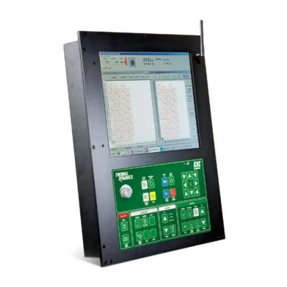
Thermal Dynamics iCNC Performance Service And Installation Manual (138 pages)
CNC CONTROLLER
Brand:
Thermal Dynamics
| Category:
Controller
| Size: 15 MB
Table of Contents
Table of Contents
9
Section 1: Safety
13
1.01 Safety Precautions - ENGLISH
13
1.02 Précautions de Sécurité - FRENCH CANADIAN
18
Section 2: Specifications
23
System Description
23
Specification
23
Dimensions
24
Basic System Layout
25
Grounding and Cable Routing
26
Low Cost Ground Rod Tester
26
Connector Locations
28
Section 3: I/O Descriptions
29
General
29
J45 Inputs
29
Input Pin Arrangement
29
Input Example
30
Input Naming
30
J46 Outputs
31
Output Pin Arrangement
31
Output Example
32
Output Naming
32
Wiring Multiple Oxyfuel Lifters
33
Wiring Multiple Stations
34
Section 4: Motion
35
Motion in General
35
Motion Signal Characteristics
35
J47 Servo Connector
36
Servo Pin Arrangement
36
J48 Encoder Connector
37
Encoder Pin Arrangement
37
Servo Connection Examples
38
Analog Speed Signal with Yaskawa SGDV
38
Step/Dir Signal with Yaskawa SGDV
38
Analog Speed Signal with Panasonic A5
39
Step/Dir with Panasonic A5 W/O Encoder Feedback
39
Step/Dir Signal Without Encoder Feedback
40
Section 5: Input Power
41
Power Supply
41
Power Connector
41
Power Connector Pin Arrangement
41
SECTION 6: Ihc
43
Lifter Specifications
43
Voltage Divider Dimensions
44
Connector Locations
44
IO Example Connections
45
J54 Lifter
46
J55 Plasma
47
J53 Cnc
48
Ihc Software
49
Pierce/Cut Sequence
49
IO Bits Tab
50
Service Tab
51
Installation Tab
52
Parameter Limits
53
SECTION 7: Icnc SETUP
55
Initial Checks
55
Starting Icnc Setup
56
Motion, STEP/DIR
57
Drive and Encoder Polarities Step/Dir
58
Encoder Values Step/Dir
59
Max Speed Adjustment Step/Dir
60
Motion Parameters
60
Motion, Analog Speed
62
Drive Configuration Analog Speed
62
Drive and Encoder Polarities Analog Speed
63
Encoder Values Analog Speed
64
Drift Adjustment Analog Speed
65
Max Speed Adjustment Analog Speed
65
Max Speed Test Analog Speed
66
Min Speed Test Analog Speed
66
Motion Parameters
67
I/O General
69
I/O and Delay
71
7.5.2.1 I/O and Delay Plasma Cutting
71
7.5.2.2 Advanced
73
7.5.2.3 I/O and Delay Gas Cutting
74
7.5.2.4 Custom
75
7.5.2.5 Advanced
76
7.5.2.6 I/O and Delay Line Marking
76
Custom
77
Advanced
78
I/O Point Marking
79
I/O Outbit Names
80
I/O Inbit Names
80
Cutting Table Data
81
Homing / Limits
81
Down Draft
85
Others
86
General
86
Thc/Plasma Settings
87
Teach in
88
Get Serial Number
88
Diagnostic Information
88
Advanced Diagnostics
88
Update Software
88
Backups
88
Backup Machine Settings
88
Restore Machine Settings
89
Restore Machine Settings from Backwall Backup USB
89
Create a System Image
91
Restore a System Image
92
Rotating Axis
92
Tangential Rotation
92
Hard Drive Lock
92
7.10.1 Change Status
92
Tool Offsets
93
Measuring the Offset Using a Plasma Power Supply
93
Setting the Tool Offset Values
94
Section 8: Maintenance and Troubleshooting
95
Maintenance
95
Troubleshooting
95
Using Machine Info Screen for Troubleshooting
95
8.2.1.1 Position and Speed Info
95
8.2.1.2 Outbits Tab
96
8.2.1.3 Inbits Tab
97
8.2.1.4 Diagnostic Tools Tab
97
Boot and Power Issues
98
Piercing and Cutting Issues
98
Motion Issues
99
IO Issues/ Error Messages
99
UI Errors
100
Cut Quality
100
Replacement Parts
101
Appendix A
103
Appendix A
103
Bios Settings
103
A.1 Bios Settings
103
Setting up SDSK Series Motors
104
Connecting to the Servo Motor
104
Autotune
106
A.2.2 Autotune
106
Settings
109
A.2.3 Settings
109
Changing Motor Rotation Direction
110
Final Settings
110
Appendix B
111
Appendix B
111
Servo Adapter Card (Optional
111
B1.1 Dimensions
111
Output Connectors
112
B.1.2 Output Connectors
112
Encoder Connectors
113
Servo Connectors
113
B.1.3 Encoder Connectors
113
Input Connectors
114
B.1.5 Input Connectors
114
Teknic Connectors
115
B.1.6 Teknic Connectors
115
E-Stop Connectors
116
B.1.7 E-Stop Connectors
116
Servo Adapter Card Connection Example
117
Servo Adapter Card Alternative Connections
118
Motors and Gearboxes
119
Teknic Nema23
119
Neugart PLPE 70
119
Teknic Nema34
120
Neugart PLPE 90
120
B.2.3 Teknic Nema34
120
Lifter Motor
121
B.2.5 Lifter Motor
121
75VDC Power Suply Dimensions
122
Thermal Dynamics A-Series Automation PCB
123
Cable Drawings
124
Yaskawa Speed Loop Example
124
B.4 Cable Drawings
124
Panasonic A5 Speed Loop Example
125
Panasonic A5 STEP/DIR Example
126
Lifter Cable
127
B.4.4 Lifter Cable
127
Collision Sensor Cable
128
Plasma and VDC Adapter Cable
129
A-Series Plasma Adapter Cable
130
Auto-Cut 200 XT Plasma Adapter Cable
131
Ultra-Cut XT & Auto-Cut 300 XT Plasma Adapter Cable
132
B.4.10 Ultra-Cut XT Communication Cable
133
B.4.11 Ultra-Cut & Auto-Cut Blue Units (Sanrex) Plasma Adapter Cable
134
Connecting Ihc to Panasonic A5
135
B.4.13 Y2 Alignment Cable for Teknic Motor
136
Statement of Warranty
137
Advertisement
Thermal Dynamics iCNC Performance Operator's Manual (118 pages)
PERFORMANCE CNC CONTROLLER
Brand:
Thermal Dynamics
| Category:
Controller
| Size: 10 MB
Table of Contents
Table of Contents
9
Section 1: Safety
11
Safety Precautions - ENGLISH
11
Précautions de Sécurité - FRENCH CANADIAN
16
Section 2: Specifications
21
System Description
21
Specification
21
Section 3: Operation
23
Overview Main Screen
23
Process Selection / Plasma and Gas
28
Front Panel Buttons
30
ON/OFF Button Descriptions and Functions
33
Auxiliary Button Descriptions and Functions
33
Plasma Button Descriptions and Functions
34
Oxyfuel Button Descriptions and Functions
35
Starting Procedure
36
Homing Procedure
37
Jog
37
How to Proceed When Something Happens
39
Advanced Process Selection Features
42
SECTION 4: Ihc
49
Pierce/Cut Sequense
49
Ihc User Interface
50
Main Settings
52
System Setup & Diagnostic Menus
53
Section 5: Nest
59
Promotion Nest
59
Toolbar
61
Toolbar Functions
62
File Menu
79
View Menu
81
Tools Menu
82
Marking
87
Autonest
87
Cutting
89
Special Tools
92
Ruler
95
Options Menu
96
ESSI Options
98
EIA Input Options
100
EIA Ouput Options
101
Nesting Options
103
Language Options
104
Registration Menu
104
Help Menu
104
List Windows
104
Miscellaneous
106
Section 6: Maintenance and Troubleshooting
111
Maintenance
111
Cut Quality
111
Oxy Fuel Cutting Quality
112
Troubleshooting
114
Replacement Parts
116
Statement of Warranty
117
Advertisement
Related Products
Thermal Dynamics IHC XT
Thermal Dynamics Categories
Welding System
Power Supply
Cutter
Controller
Flashlight
More Thermal Dynamics Manuals
Login
Sign In
OR
Sign in with Facebook
Sign in with Google
Upload manual
Upload from disk
Upload from URL