
Related Manuals for Thermal Dynamics iCNC Performance


Summary of Contents for Thermal Dynamics iCNC Performance
- Page 1 ® INPUT VOLTAGE iCNC PERFORMANCE CNC CONTROLLER Service and Installation Manual Revision: AB Issue Date: February, 2016 Manual No.: 0-5401 Thermal-Dynamics.com...
- Page 2 WE APPRECIATE YOUR BUSINESS! Congratulations on your new Thermal Dynamics product. We are proud to have you as our customer and will strive to provide you with the best service and reliability in the industry. This product is backed by our extensive warranty and world-wide service network. To locate your nearest distributor or service agency call 1-800-752-7622, or visit us on the web at www.thermal-...
- Page 3 Publication Date: September 25, 2015 Revision Date: February, 2016 Record the following information for Warranty purposes: Where Purchased: ___________________________________ Purchase Date:______________________________________ iCNC Performance Serial #:_______________________________...
- Page 4 Be sure this information reaches the operator. You can get extra copies through your supplier. CAUTION These INSTRUCTIONS are for experienced operators. If you are not fully familiar with the principles of operation and safe practices for arc welding and cutting equipment, we urge you to read our booklet, “Precautions and Safe Practices for Arc Welding, Cutting, and Gouging,”...
- Page 5 ASSUREZ-VOUS QUE CETTE INFORMATION EST DISTRIBUÉE À L’OPÉRATEUR. VOUS POUVEZ OBTENIR DES COPIES SUPPLÉMENTAIRES CHEZ VOTRE FOURNISSEUR. ATTENTION Les INSTRUCTIONS suivantes sont destinées aux opérateurs qualifiés seulement. Si vous n’avez pas une connaissance approfondie des principes de fonctionnement et des règles de sécurité...
- Page 6 This Page Intentionally Blank...
- Page 7 2004/108/EC The Electromagnetic Compatibility Directive hereby declare that Equipment: Plasma Cutting CNC Controller Model Name/Number: iCNC Performance Market Release Date: August 19, 2015 is in conformity with the applicable requirements of the following harmonized standards Conforms to requirements of IEC 61326-1:2012...
- Page 8 WARNING This Class A equipment is not intended for use in residential locations where the electrical power is provided by the public low-voltage supply system. There may be potential difficul- ties in ensuring electromagnetic compatibility in those locations, due to conducted as well as radiated disturbances.
-
Page 9: Table Of Contents
TABLE OF CONTENTS SECTION 1: SAFETY ..................1-1 1.01 Safety Precautions - ENGLISH ................ 1-1 1.02 Précautions de sécurité - FRENCH CANADIAN ..........1-6 SECTION 2: SPECIFICATIONS ................2-1 System Description ..................2-1 Specification ....................2-1 Dimensions ..................... 2-2 Basic System Layout ..................2-3 Grounding and Cable Routing ................. - Page 10 TABLE OF CONTENTS iHC Software ....................6-7 6.7.1 Pierce/Cut Sequence ..................6-7 6.7.2 IO Bits Tab ...................... 6-8 6.7.3 Service Tab ..................... 6-9 6.7.4 Installation Tab ....................6-10 6.7.5 Parameter Limits ..................6-11 SECTION 7: iCNC SETUP .................. 7-1 Initial Checks ....................7-1 Starting iCNC Setup ..................
- Page 11 TABLE OF CONTENTS 7.8.3 Restore Machine Settings from Backwall Backup USB ......... 7-35 7.8.4 Create a System Image ................. 7-37 7.8.5 Restore a System Image ................7-38 Rotating Axis ....................7-38 7.9.1 Tangential Rotation ..................7-38 7.10 Hard Drive Lock .................... 7-38 7.10.1 Change Status ....................
- Page 12 TABLE OF CONTENTS B.2.6 75VDC Power Suply Dimensions ..............B-12 Thermal Dynamics A-Series Automation PCB ..........B-13 Cable Drawings ..................... B-14 B.4.1 Yaskawa Speed Loop Example ..............B-14 B.4.2 Panasonic A5 Speed Loop Example .............. B-15 B.4.3 Panasonic A5 STEP/DIR Example ..............B-16 B.4.4...
-
Page 13: Section 1: Safety
Performance SECTION 1: SAFETY 1.01 Safety Precautions - ENGLISH WARNING: These Safety Precautions are for your protection. They summarize precautionary informa- tion from the references listed in Additional Safety Information section. Before performing any instal- lation or operating procedures, be sure to read and follow the safety precautions listed below as well as all other manuals, material safety data sheets, labels, etc. - Page 14 Performance ELECTRICAL SHOCK -- Contact with live electrical parts and ground can cause severe injury or death. DO NOT use AC welding current in damp areas, if movement is confined, or if there is danger of falling. 1. Be sure the power source frame (chassis) is connected to the ground system of the input power.
- Page 15 Performance CYLINDER HANDLING -- Cylinders, if mishandled, can rupture and violently release gas. Sudden rupture of cylinder, valve, or relief device can injure or kill. Therefore: 1. Use the proper gas for the process and use the proper pressure reducing regulator designed to operate from the compressed gas cylinder.
- Page 16 Performance Meaning of symbols - As used throughout this manual: Means Attention! Be Alert! Your safety is involved. Means immediate hazards which, if not avoided, will result in immediate, serious DANGER personal injury or loss of life. CAUTION Means potential hazards which could result in personal injury or loss of life.
- Page 17 Performance This Page Intentionally Blank Manual 0-5401 SAFETY INSTRUCTIONS...
-
Page 18: 1.02 Précautions De Sécurité - French Canadian
Performance 1.02 Précautions de sécurité - FRENCH CANADIAN AVERTISSEMENT : Ces règles de sécurité ont pour but d’assurer votre protection. Ils récapitulent les informations de précaution provenant des références dans la section des Informations de sécurité supplémentaires. Avant de procéder à l’installation ou d’utiliser l’unité, assurez-vous de lire et de suivre les précautions de sécurité... - Page 19 Performance 5. Assurez-vous de ne pas excéder la capacité de l’équipement. Par exemple, un câble de soudage surchargé peut surchauffer et provoquer un incendie. 6. Une fois les opérations terminées, inspectez l’aire de travail pour assurer qu’aucune étincelle ou projection de métal incandescent ne risque de provoquer un incendie ultérieurement.
- Page 20 Performance LES VAPEURS ET LES GAZ -- peuvent causer un malaise ou des dommages corporels, plus par- ticulièrement dans les espaces restreints. Ne respirez pas les vapeurs et les gaz. Le gaz de protec- tion risque de causer l’asphyxie.
- Page 21 Performance 4. N’utilisez pas l’équipement de façon abusive. Gardez l’équipement à l’écart de toute source de chaleur, notamment des fours, de l’humidité, des flaques d’eau, de l’huile ou de la graisse, des atmosphères corrosives et des intempéries. 5. Laissez en place tous les dispositifs de sécurité et tous les panneaux de la console et maintenez-les en bon état.
- Page 22 Performance MISE EN GARDE L’équipement pourrait basculer s’il est placé sur une surface dont la pente dépasse 15°. Vous pourriez vous blesser ou endommager l’équipement de façon importante. 15° Art# A-12726 MISE EN GARDE Soulevez à l’aide de la méthode et des points d’attache illustrés afin d’éviter de vous blesser ou d’endommager...
-
Page 23: Section 2: Specifications
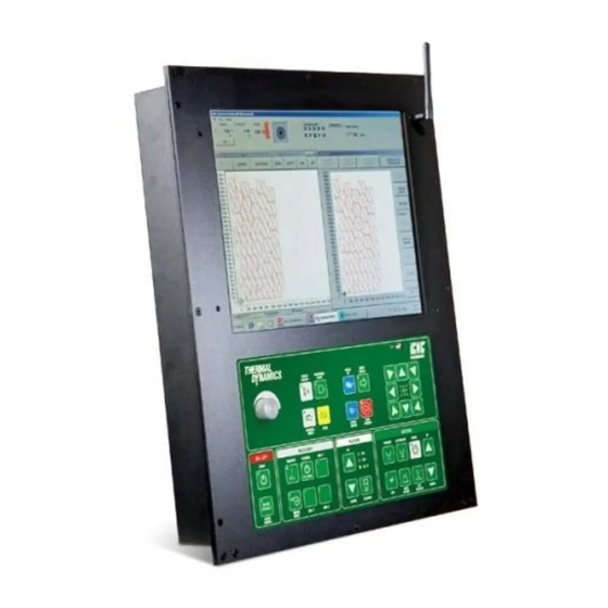
System Description iCNC Performance is intended for shape cutting control. iCNC Performance has motion control, I/O, user interface and an optional plasma height control built all in one package. These units are not field repairable. Unauthorized opening of the unit will void the warranty. -
Page 24: Dimensions
Performance Dimensions iCNC Performance has 4 x 8mm holes for mounting screws. There is a 16mm [0.63in] collar going around the unit. Dimensions and weight (this does not take in account the dimensions for the connectors or cables): Width: 408 [16.063] Height: 492 [19.37]... -
Page 25: Basic System Layout
Perfromance Basic System Layout iCNC Performance has connections for inputs, outputs, motion control and a communication port. Usually the outputs (grounding) controls relays and all inputs needs to be dry contact or common grounding inputs (more details on I/O section). -
Page 26: Grounding And Cable Routing
Performance Grounding and Cable Routing Star Ground on Cutting Table Remote Arc Gas Control Module Torch Starter (RAS-1000) Primary location Power Supply Cutting Machine / Gantry #4 AWG Lifter Ground #4 AWG Ground Note: The gas control module can be mounted... - Page 27 iCNC Perfromance 4. Assemble the transformer and power resistor in a metal box. Connect a 3 wire (w/gnd) power cord with ground wire attached to the metal box for safety. If a plastic box is used instead, connect the transformer core and the resistor mounts to the power cord ground wire.
-
Page 28: Connector Locations
Performance Connector Locations On the back of the iCNC Performance you have connectors for: BACKUP DO NOT REMOVE ® Picture reference ID Name Mating connector (example) Inputs 25 pin female D-Sub, Wurth 618 025 249 23 Outputs 25 pin male D-Sub, Wurth 618 025 248 23... -
Page 29: Section 3: I/O Descriptions
SECTION 3: I/O DESCRIPTIONS General iCNC Performance provides input and output connectors for external devices. This sections covers the back wall connectors. You can change the input or output description name in iCNC Settings, instructions how to change setting are later described in this section. -
Page 30: Input Example
Input Naming iCNC Performance comes with pre named inputs. Input names are just descriptions and most inputs can be mapped to any of the functions available on the device. You can change the input description names in iCNC Settings, see more details on iCNC Settings section. -
Page 31: J46 Outputs
iCNC Perfromance J46 Outputs All outputs are active low. So the output pin will be low when active. 3.3.1 Output Pin Arrangement Pin number Output number Default name Description Outbit 0 Low PreHeat Output pin connected to GND when active Outbit 2 Gas Torch Up Output pin connected to GND when active... -
Page 32: Output Example
Output naming iCNC Performance comes with pre named outputs. Output names are just descriptions and most outputs can be mapped to any of the functions available on the device. You can change the output description names in iCNC Settings, see more details on iCNC Settings section. -
Page 33: Wiring Multiple Oxyfuel Lifters
iCNC Perfromance 3.3.4 Wiring Multiple Oxyfuel Lifters Using multiple oxyfuel torches J46 #24 24VDC Output Torch1 Up Output J46 #2 Torch Up (all) 24VDC Relay With Back EMF diode J46 #15 Torch Down (all) Common Torch1 Up Common J46 #13 GND Torch1 Down Output Torch1 Up/Down... -
Page 34: Wiring Multiple Stations
Performance 3.3.5 Wiring Multiple Stations Using multiple oxyfuel stations with select switches J46 #14 Cut Oxygen output J46 #17 High PreHeat output J46 #24 24VDC Output Station select 1 Cutting Oxygen Solenoid Torch 1 Output 24VDC Relay With Back EMF diode... -
Page 35: Section 4: Motion
SECTION 4: MOTION Motion in General iCNC Performance provides motion output for Step/Dir for position loop and +/- 10VDC analog signal for speed loop. iCNC Performance also has an encoder connector for position feedback from a servo drive or encoders. -
Page 36: J47 Servo Connector
Performance J47 Servo Connector 4.2.1 Servo Pin arrangement Pin number Name Description X-Axis Direction + Differential Direction signal for X-Axis. 5V logic X-Axis Step + Differential Step signal for X-Axis. 5V logic Y-Axis Direction + Differential Direction signal Y-Axis. 5V logic. -
Page 37: J48 Encoder Connector
iCNC Perfromance J48 Encoder Connector 4.3.1 Encoder Pin Arrangement Pin number Name Description X-Axis A+ Differential encoder input signal for X-Axis A+ X-Axis B+ Differential encoder input signal for X-Axis B+ Y-Axis A+ Differential encoder input signal for Y-Axis A+ Y-Axis B+ Differential encoder input signal for Y-Axis B+ Y2-Axis A+... -
Page 38: Servo Connection Examples
Performance Servo Connection Examples 4.4.1 Analog Speed Signal with Yaskawa SGDV Cable shield to J47 connector casing Yaskawa SGDV V-REF J47 GND #8 Cable shield to J48 connector casing J48 A- #9 J47 X- Speed #5 Signal GND /PAO... -
Page 39: Analog Speed Signal With Panasonic A5
iCNC Perfromance 4.4.3 Analog Speed Signal with Panasonic A5 Cable shield J47 connector casing Panasonic A5 J47 GND #8 Cable shield J48 connector casing J48 A- #9 J47 X- Speed #5 Signal GND J48 A+ #1 J47 Enable #14 /SRV-ON J48 B- #10 COM- J47 GND #15... -
Page 40: Step/Dir Signal Without Encoder Feedback
Performance 4.4.5 Step/Dir Signal without Encoder Feedback Cable shield to J47 connector casing Gecko G201X/G210 J47 DIR + #1 Direction J47 STEP + #2 Step Disable J47 GND #15 Common Current Set J47 5VDC #7 24VDC Relay With Back EMF diode... -
Page 41: Section 5: Input Power
Perfromance SECTION 5: INPUT POWER Power Supply iCNC Performance comes with an optional 24VDC 6.67A power supply. The connector for the main power for the iCNC is an IEC C13, that should be rated for 10A 250V. CAUTION Wire sizes are for reference only. The installation must conform to national and local codes for the type and method of wire being used. - Page 42 Performance This Page Intentionally Blank INPUT POWER Manual 0-5401...
-
Page 43: Section 6: Ihc
Performance SECTION 6: iHC Lifter Specifications Arc voltage division 1:80 Arc voltage measurement range 0 - 327VDC Arc voltage measurement resolution 0.02V Arc voltage measurement accuracy ± 0.2% Arc voltage set range 50 - 300VDC Motor type Oriental Motor PKP266D28A-L Motor step angle 1.8 °... -
Page 44: Voltage Divider Dimensions
25pin female D-Sub Wurth 618 025 249 23 37pin male D-Sub Wurth 618 037 248 23 CAUTION When iHC is used with iCNC Performance all CNC to iHC signals are wired internally. Usually there is no need to connect anything to J53 CNC connector. Manual 0-5401... -
Page 45: Io Example Connections
Performance IO Example Connections Manual 0-5401... -
Page 46: J54 Lifter
Performance J54 Lifter Name Description Jumper Jumper to J55 pin #1 Not in use Shield Cable shield GND Out 2 GND for 5VDC in pin #16 Stepper A+ Motor current output 2.5A, max 40V Stepper A- Motor current output 2.5A, max 40V... -
Page 47: J55 Plasma
Performance J55 Plasma Name Description Jumper Jumper to connector J54 pin #1 Not in use Plasma Start NO NO Relay contact, max 48V 0.5A IHS active COM NO Relay contact, max 48V 0.5A Marking COM NO Relay contact, max 48V 0.5A... -
Page 48: J53 Cnc
Performance J53 CNC CAUTION When iHC is used with iCNC Performance all CNC to iHC signals are wired internally. Usually there is no need to connect anything to J53 CNC connector. Name Description IHS Start In IHS Start input, activate by providing a dry closing con-... -
Page 49: Ihc Software
Performance iHC Software 6.7.1 Pierce/Cut Sequence Pierce/Cut Flow Sequence: 1. IHS Start activated torch starts to find the plate. 2. Torch reaches slowdown height and starts to move slowly. 3. Torch touches the plate. 4. Torch moves to ignition height and gives command to start the plasma. -
Page 50: Io Bits Tab
IO Bits Tab This tab displays the status of various system signals for diagnostic purposes. I/O bits are separated to inputs (signals that come from other devices to iHC) and outputs (signals that go from the iHC to iCNC Performance). Inputs 1. -
Page 51: Service Tab
Performance Outputs 14. System Error (Inverted) Can be connected to CNC controllers external stop 15. Optional Reserved for future use 16. Sense 24V Output for voltage divider board. 17. IHS Active Outbit which is active form the time IHS Start turns active until Ignition Height has been reached. -
Page 52: Installation Tab
Performance 6.7.4 Installation Tab These parameters are password protected. Some parameters are the same as on the Advanced Tab. • Encoder pulse edges per meter Determined by the type of encoder and the threaded shaft of the lifter.* • Full Speed The maximum speed of the lifter. Full Speed is used above Slow Down Height. -
Page 53: Parameter Limits
Performance 6.7.5 Parameter Limits Parameter name Default Adjust speed 3000mm/min 9600 Collision recovery delay Collision retract height Cut height Cut height AVC delay 0.5s Manual acceleration 0.3g 0.01 Manual deceleration 0.3g 0.01 Encoder pulses per meter 1280000p/m 255M Find plate speed... - Page 54 Performance This Page Intentionally Blank 6-12 Manual 0-5401...
-
Page 55: Section 7: Icnc Setup
Performance SECTION 7: iCNC SETUP 1. Motion 1.1. Drive con guration 2. I/O 1.2. Drive and encoder polarities 3. Cutting table data 1.3. Encoder values 5. Others 1.4. Drift adjustment (only analog speed) 6. Backups 1.5. Max speed adjustment 7. -
Page 56: Starting Icnc Setup
Performance Starting iCNC Setup iCNC Performance installation settings are done from iCNC setup. You can start iCNC settings by: 1. In Info System Status screen select file --> iCNCSetup 2. Click Enter Administrator Mode and type in the password when prompted to change settings. Password pmcs1... -
Page 57: Motion, Step/Dir
Performance Motion, STEP/DIR CAUTION Some settings and windows differ based on your drive configuration at this screen. This section will cover Step/Dir mode. NOTE! Check the “Disable servo failure detect” box before running motion tests. 7.3.1 Drive Configuration Step/Dir Number of axis Select the number of controllable X/Y axes, 2 or 3. -
Page 58: Drive And Encoder Polarities Step/Dir
Performance When the controller reboots, you will be prompted to transfer the newly modified ROBOPRM1.DAT file to the background CPU. Select YES and give the password to complete this action. When completed, restart iCNC Setup as explained above. 7.3.2 Drive and Encoder Polarities Step/Dir •... -
Page 59: Encoder Values Step/Dir
Performance 7.3.3 Encoder Values Step/Dir Put the Drive Enable on the front of the controller to “ON” It is advisable to use low speeds for testing, decrease speed from speed potentiometer, Move the machine to the front of the rail or reference mark. Reset the encoder counters by pressing the Reset counters button or the yellow 0,0 button in the panel. -
Page 60: Max Speed Adjustment Step/Dir
Performance 7.3.4 Max Speed Adjustment Step/Dir CAUTION Machine will run with max speed during the test. Keep motors off the rails while performing the test. This will let you drive with the maximum speed, making it possible to see the true speeds for each axis. Default Step frequency is 200kHz, decreasing the Max speed percentage will scale down the output pulse frequency. - Page 61 Performance • Max trial run speed is normally set equal to the Max settable speed. • Min settable speed is set to your lowest dependable speed. The system enters this value in automatically after complet- ing the Min speed test.
-
Page 62: Motion, Analog Speed
Performance Motion, Analog Speed CAUTION Some settings and windows differ based on your drive configuration at this screen. This section will cover Analog Speed mode. NOTE! Check the “Disable servo failure detect” box before running motion tests. 7.4.1 Drive Configuration Analog Speed Number of axis Select the number of controllable X/Y axes 2 or 3. -
Page 63: Drive And Encoder Polarities Analog Speed
Performance When the controller reboots, you will be prompted to transfer the newly modified ROBOPRM1.DAT file to the background CPU. Select YES and give the password pmcs1 to complete this action. When completed, restart iCNC Setup as explained in “7.2 Starting iCNC Setup”... -
Page 64: Encoder Values Analog Speed
Performance 7.4.3 Encoder Values Analog Speed Put the Drive Enable on the front of the controller to “ON” It is advisable to use low speeds for testing, decrease speed from speed potentiometer, Move the machine to the front of the rail or reference mark. Reset the encoder counters by pressing the Reset counters button or the yellow 0,0 button in the panel. -
Page 65: Drift Adjustment Analog Speed
Performance 7.4.4 Drift Adjustment Analog Speed Drift Adjustment from iCNC Setup will open the positioning loop and allow the machine to drift if the electrical settings are not perfect. Put the Drive Enable on the front of the controller to “ON” and adjust the motion to zero drift using the + and - buttons. -
Page 66: Max Speed Test Analog Speed
Performance 7.4.6 Max Speed Test Analog Speed CAUTION Machine will run with max speed during the test. Keep motors off the rails while performing the test. This test is elementary for proper operation of the controller. In most cases it is safe to do this test with the drives disengaged, because the majority of the system inertia is normally within the motor gearbox, and the machine motion friction is very small. -
Page 67: Motion Parameters
Performance After the test speeds appear, select Calculate low speed corrections. With optimum drives and perfect adjustment, all the correction values will come in at 1. Press the ZERO push button on the controller, then select OK when ready. - Page 68 Performance • Corner angle w/o slowdown specifies the maximum corner angle to be driven without any speed limitations. 15000 mdegrees is same as 15 degrees. • Automatic drift adjustment drift is periodically measured and compensated automatically. • Acceleration S-Curve Enabled enables/disables S curve acceleration for smoother motion with high acceleration values.
-
Page 69: I/O General
Performance I/O settings determine the behavior of the machine when hitting a limit switch, what happens in the piercing sequence, in/output names etc. 7.5.1 I/O General • Limit switches If a single input is used, select the input and polarity. If you have separate limit switches for all direction choose separate inputs and set your input configuration for each axis. - Page 70 If the Teknic check box is checked inbit has to turn on after enable output has been turned on. Y2 alignment with STEP/DIR signals Wiring from iCNC Performance iCNC PERFORMANCE SERVO DRIVES...
-
Page 71: I/O And Delay
Performance 7.5.2 I/O and Delay Here you can map your I/Os and delays. When you open the IO and Delay you might be prompted with a similiar window like below: This window indicates that the active and displayed settings do not match. In the above example picture gas IO settings dif- fer in the display from the active ones. - Page 72 Performance Machine moves to pierce point Machine moves to next pierce point Outbit 7 ON in04 interrupt Outbit 7 OFF Outbit 7 OFF in04 interrupt Outbit 7 ON - Move torch up - IHS Start activates - Pierce Delay...
-
Page 73: 7.5.2.2 Advanced
Performance 7.5.2.2 Advanced • External stop if main arc is not ok You can Enable/Disable the feature. When enabled if plasma arc is lost during the cut process CNC will stop motion, turn off cut process IOs and give a message that that arc has been lost during cutting. -
Page 74: 7.5.2.3 I/O And Delay Gas Cutting
Performance 7.5.2.3 I/O and Delay Gas Cutting Here you can map the I/O’s and set the delay times for oxy fuel cutting. You have 4 pre set parameter sets and a custom to create your own. Set 1 is used when only preheat, cut oxygen and vent signals are used. -
Page 75: 7.5.2.4 Custom
Performance 7.5.2.4 Custom Machine moves to pierce point Machine moves to next pierce point Outbits 8 and 12 ON Outbits 2, 8 and 12 ON Outbit 3 ON Outbit 14 ON Outbits 1, 8, 12 ON Outbit 1, 8, 12 ON... -
Page 76: 7.5.2.5 Advanced
Performance 7.5.2.5 Advanced • Activated outbits during program running with gas process Enable/Disable the feature. This will turn the selected outbit ON always when gas cutting program is running. • OutBit Number Outbit that will be turned and kept on when gas cutting process is running •... -
Page 77: Custom
Performance 7.5.3 Custom Machine moves to pierce point Machine moves to next pierce point Outbits 6 ON in04 interrupt Outbits 6 and 7 ON Outbit 6 and 7 OFF in04 interrupt Outbits 6 and 7 ON Outbit 6 and 7 ON... -
Page 78: Advanced
Performance 7.5.4 Advanced These options are the same as Plasma advanced features. • External stop if main arc is not ok Enable/Disable the feature. When enabled if plasma arc is lost during the cut process CNC will stop motion, turn off cut process IOs and give a message that that arc has been lost during cutting. -
Page 79: I/O Point Marking
Performance 7.5.5 I/O Point Marking Point marking process has only start delays, so the end sequence in the example above is put to Start Delay 4 and Start Delay5. The example above is a typical point marking I/O map when the plasma is used for point marking. This is the same as line marking but without machine movement. -
Page 80: I/O Outbit Names
Performance 7.5.6 I/O Outbit Names The reference name of the outbits can be changed here. Note that this does not change the pinout at the connector or front panel button mapping. 7.5.7 I/O Inbit Names The reference name of the inbits can be changed here. Note that this does not change the pin out at the connector. -
Page 81: Cutting Table Data
Performance Cutting Table Data 7.6.1 Homing / Limits • Speed to switches Speed used to find the limit switch. • Speed from switches Speed used to drive out from the limit switch. • Enable homing Enable/Disable the feature. • Set absolute zero after homing Enable/Disable automatic absolute zero setting after homing is done. - Page 82 Performance Example on setting software limits: 1. Set you homing switches in I/O General. Typically the X/Y limits switches are used and there is no need for separate homing switches. 2. Be sure that “Enable Homing” is checked and “Ask for Homing on Startup” is checked. Speed to Switches default is 3500mm/min and from is 500 mm/min.
- Page 83 Performance 5.Put drive enable button to ON. 6. Open “Next job preview” window and click 7. Click “Home Machine”. 8. After homing is done press the button and move the machine using the directional buttons to the positive Y and X until you reach the position where the software limit will be. Write down the coordinate values shown in the “Info screen”.
- Page 84 Performance 7-30 iCNC SETUP Manual 0-5401...
-
Page 85: Down Draft
Performance 7.6.2 Down Draft • Use down draft Enable/Disable down draft feature. • Start Homing Starts homing procedure to configure sections. • Torch in position Apply position from home position to transfer point of 1st and 2nd section • Number of segments Give the number of sections. -
Page 86: Others
Performance Others 7.7.1 General • Backward hold Enabled When enabled keeping backward button pressed in for the duration of Timeout backward movement will be performed even if button is released. • Timeout Time it takes to enable backward hold (see above). -
Page 87: Thc/Plasma Settings
Performance 7.7.2 THC/Plasma Settings • Reset Resets THC and plasma configuration settings. • THC THC type None or internal iHC. • Plasma Plasma power source model selection. Manual 0-5401 iCNC SETUP 7-33... -
Page 88: Teach In
Performance 7.7.3 Teach In Reserved for future use 7.7.4 Get Serial Number This will show the hardware ID and revision. Used for diagnostic purposes 7.7.5 Diagnostic Information Saves diagnostic information to c:\robo\Diags\. Used for debugging purposes. 7.7.6 Advanced Diagnostics Used to debug front panel buttons. -
Page 89: Restore Machine Settings
Performance • Make backup Make a backup to selected folder • Close Closes the window NOTE! If the backup is not saved in the root of the device it needs to be put there before doing a restore. Restore can only be done from the root of the device. - Page 90 Performance 3. Enter administrator mode (password pmcs1). 4. Navigate to 6. Backups --> 6.2 Restore machine settings. 5. In selected folder choose the USB drive. 6. In selected backup choose the appropriate date (usually latest one works the best).
-
Page 91: Create A System Image
Performance 12. Do the same for all files requested to be sent. 13. Some default settings will not activate before a process is applied and a cutting program has started. • Apply a process • Press the blue speed up button until it has reaches maximum value. -
Page 92: Restore A System Image
Performance 3. Select create a system image 4. Wait until search is done, select drive D: and click Next. 5. Wait until image is created. 7.8.5 Restore a System Image If the CNC is unable to properly boot in to windows the system image recovery is launched automatically. Follow instructions on screen to finish the restore procedure. -
Page 93: Tool Offsets
Performance • Unlock Unlocks the hard drive so changes can be made • Lock Locks the hard drive Lock/Unlock state change requires a windows reboot. This will be done automatically after you have confirmed your action. Tool Offsets Defining tool offsets gives the option to use example a laser pointer as the zero reference. This way the laser pointer can be used to show the zero reference point of the cutting program. -
Page 94: Setting The Tool Offset Values
Make sure to note the possible - sign in the coordinate as this will have an affect how the distance is measured. NOTE! Default tool offset using Thermal Dynamics lifter is ~X-axis 41mm [1.614”] / Y-axis -43mm [-1.693”] Setting the tool offset values 1. -
Page 95: Section 8: Maintenance And Troubleshooting
Performance SECTION 8: MAINTENANCE AND TROUBLESHOOTING Maintenance Weekly Check buttons for wear and tear. Monthly Check cables for wear and tear. Check all connectors are properly connected. Troubleshooting 8.2.1 Using Machine Info Screen for Troubleshooting CAUTION In service mode the I/Os can be forced on by clicking the I/O in the Machine Info window. If devices are connected damage can occur if the I/O is forced on and objects are not clear. -
Page 96: 8.2.1.2 Outbits Tab
Performance 8.2.1.2 Outbits Tab Outbits Displays outbits and front panel buttons status. Above picture shows the following, plasma remote button turned ON and backwall output is ON, the down draft is commanded ON by software but the button is set to OFF, drive enable is commanded ON by software but backwall output is OFF and iHC IHS start is commanded ON by software, button set to AUTO and backwall output turned ON. -
Page 97: 8.2.1.3 Inbits Tab
Performance 8.2.1.3 Inbits Tab Intbits Displays inbit state. Above picture shows that limits switches are active (there is contact between the inputs to ground). NOTE! You can jumper any desired input signal to ground and verify with this window that the CNC sees that the input closes. -
Page 98: Boot And Power Issues
Performance 8.2.2 Boot and Power Issues Problem Cause What to check Unit will not power up No main power Measure 24VDC power input, replace power supply. Poor power connection Check for proper power connector connection. Over current fuse tripped Remove all cables, leave power off for 1min. Connect only the power cable and try to boot. -
Page 99: Motion Issues
Performance 8.2.4 Motion Issues Problem Cause What to check Motors won’t move Enable OFF Turn enable switch to ON SW Enable OFF See error messages. Speed set to 0 Turn the speed potentiometer to 100%, press the speed up button to increase the speed. -
Page 100: Ui Errors
Performance 8.2.6 UI Errors Problem Cause What to check Data on the screen fills Bios settings lost Change correct bios settings. Bios settings at page “A.1 only part of the screen Bios settings” on page A-3 Data on the screen fills Wrong font settings Windows default font size changed. -
Page 101: Replacement Parts
Performance Replacement Parts Item Name Part number Power Supply 24VDC PSU 15-6025 Lifter motor Stepper motor 15-2044 Lifter axis coupler Axis coupler 15-5040 Collision sensor Inductive sensor 1pc. 15-2119 Collision sensor cable Inductive sensor cable 1pc. 15-2114 Laser pointer... - Page 102 Performance This Page Intentionally Blank MAINTENANCE AND TROUBLESHOOTING Manual 0-5401...
-
Page 103: Bios Settings
Connect a keyboard to one of the USB ports on the CNC Use arrow keys to move, enter to go into menus and select, Esc to go back in menus and +/- to move items. Turn on iCNC Performance and Press Del button on the keyboard to enter BIOS. BIOS Press F9 to load Setup Defaults -->... -
Page 104: Setting Up Sdsk Series Motors
Performance Setting up SDSK Series Motors Basic settings: • Mode: step & direction • Input Resolution: 6400 pulses/revolution • RAS Jerk Limit: 4ms • Torque Limits: 75% • Homing: Disabled • Input A & B Filtering: both 1ms • High-Level Feedback: Servo On... - Page 105 iCNC Perfromance On the next windows software will show the peak torque of the motor and it is possible to limit peak torque to protect gearbox from damage, if gearbox can’t handle peak radial and axial loads. If gearboxes are sized correctly for the motor default value 100% can be used (picture below shows 75%).
-
Page 106: Autotune
Performance A.2.2 Autotune As the motor/gearbox is not connected to rack, on the next step we can allow “Unlimited Rotation” and “Shaft Rotates Freely…”. Click on Next. If you do have the motor conencted to the rack be cautious not to break the mechanics. - Page 107 iCNC Perfromance On the next window click on Run to start Auto-tune procedure. The whole procedure will take few minutes or even up to 20 minutes. When completed, click on Next. On the next window it is possible to manually jog with the buttons in the “Jog Position” box. After being tested click on Disable. On the next window click on Next (it is possible to do Fine Tuning later on the main window) .
- Page 108 Performance APPENDIX A Manual 0-5401...
-
Page 109: Settings
iCNC Perfromance A.2.3 Settings On the main window make double check that basic settings are set as follows: - If not set automatically, set operating mode as Step & Direction - High-Level Feedback is set to Servo On - Input A & B Filtering is set to 1ms for both inputs - Torque Fold-Back is set off - Homing is disabled - Input Resolution is set to 6400pulses/revolution... -
Page 110: Changing Motor Rotation Direction
Performance A.2.4 Changing Motor Rotation Direction You can change the motor rotation direction from the clear path software by checking and unchecking the box “Reverse direction”. A.2.5 Final Settings After basic motor settings have been set, check servo error settings in icncSetup --> IO General. Then adjust max pulse speed on iCNC Setup –... -
Page 111: Servo Adapter Card (Optional
Output section Encoder section Servo section Inputs section Teknic section External stop section The servo adapter card provides screw on terminals with connectors for all iCNC performance signals. B1.1 Dimensions [10.67] ( 262 ) ( [10.32] ) ( 138 ) ( [5.43] ) -
Page 112: Output Connectors
Performance B.1.2 Output Connectors OUTPUTS ENCODER SERVO INPUTS OUTPUTS Connectors Outputs 1-4, mating connector Wurth P/N 691321300010 Pin number Name Description XX-NO Normally open (NO) relay contact, max rating 230VAC/3A 24VDC/2A XX-COM Common (COM) to above signal XX-NO Normally open (NO) relay contact, max rating 230VAC/3A 24VDC/2A... -
Page 113: Encoder Connectors
iCNC Perfromance B.1.3 Encoder Connectors X-A+ X-A- X-B+ X-B- Y-A+ Y-A- Y-B+ Y-B- OUTPUTS ENCODER SERVO INPUTS Y2-A+ Y2-A- Y2-B+ Y2-B- ENCODER Connectors X/Y/Y2 ENC, mating connector Wurth P/N 691361300006 Pin number Name Description 5VDC Output, max rating 1A Differential encoder input, only 5V input Differential encoder input, only 5V input Differential encoder input, only 5V input Differential encoder input, only 5V input... -
Page 114: Input Connectors
Performance B.1.5 Input Connectors OUTPUTS ENCODER SERVO INPUTS INPUTS Connectors Inputs 1-4, mating connector Wurth P/N 691361300008 Pin number Name Description IN XX Input signal, connect to GND to activate input IN XX Input signal, connect to GND to activate input... -
Page 115: Teknic Connectors
iCNC Perfromance B.1.6 Teknic Connectors OUTPUTS ENCODER SERVO INPUTS Connectors CTRL X/Y/Y2, mating connector Molex P/N 39-01-2080 Pin number Name Description Output + Servo OK + signal, 5V logic Input B+ Step + signal, 5V logic Input A+ Direction + signal, 5V logic Enable + Enable signal +, 5V logic Output -... -
Page 116: E-Stop Connectors
Performance B.1.7 E-Stop Connectors OUTPUTS ENCODER SERVO INPUTS Connector E-Stop, mating connector wurth P/N 691361300004 Pin number Name Description E1 - OUT NC input, provide a dry contact to E1 IN E1 IN NC input, provide a dry contact to E1 - OUT... -
Page 117: Servo Adapter Card Connection Example
Inputs 1 E-Stop OUTPUTS ENCODER SERVO INPUTS Sub-D 25 Sub-D 15 Sub-D 15 Sub-D 25 Female Female Male Male Sub-D 15 Sub-D 15 Male Female Power Connector Sub-D 25 Sub-D 25 E1/E2 Male Female To iCNC Performance Manual 0-5401 APPENDIX B... -
Page 118: Servo Adapter Card Alternative Connections
Performance B.1.9 Servo Adapter Card Alternative Connections Using a single input (In00) with 4 over travel switches Set limit switches to X-home inputs in the setup, see section 7.5.1 Limits Limits4 COM Limits4 NC Over travel Y- Limits3 COM... -
Page 119: Motors And Gearboxes
iCNC Perfromance Motors and Gearboxes B.2.1 Teknic Nema23 5.20 I/O Connector .205 THRU 53.85 2.120 Power USB Access Connector [L 2.54] L .100 44.45 20.58±0.76 1.750 37.68 .810±.03 1.483 1.90±0.10 10.82 .075±.004 .426 81.85±0.76 Recommended 3.222±.03 .118 Clearance for USB Access .118 .472 9.53 -... -
Page 120: Teknic Nema34
Performance B.2.3 Teknic Nema34 [L .100] L 2.54 73.03 - 0.06 0.000 32.48 2.875 - 0.002 1.279 2.03 0.080 98.43 0.220 5.60 THRU 3.875 Recommended [1.250 .008] clearance for USB 31.75 .020 cable 0.197 45° 0.197 90° 108.95 ±0.76 4.289 ±0.030... -
Page 121: Lifter Motor
iCNC Perfromance B.2.5 Lifter Motor 22.4 [0.882] [0.063] [2.126] 47.14 56.44 [1.856] [2.220] ø 8 [0.315] ø 4.5 [0.177] ø 38.1 [1.50] Manual 0-5401 APPENDIX B B-11... -
Page 122: 75Vdc Power Suply Dimensions
Performance B.2.6 75VDC Power Suply Dimensions AC Input Connector / Pinout [0.26] [7.53] [0.05] wire entry view Pos. 115 VAC 230 VAC DC output AC IN AC IN Inlet connector Jump to 9 AC IN Jump to 10 Jump to 9 6.35... -
Page 123: Thermal Dynamics A-Series Automation Pcb
3 ON rest OFF 30:1 Div 1 4 ON rest OFF 40:1(INOVA) 5 ON rest OFF 50:1(IHT, SC3000, Hypertherm) 6 ON rest OFF 80:1(iHC, iCNC Performance) CONTACT M-ARC START Switches: SW2 = Tip sensing ON SW3 = Tip sensing during cutting ON... -
Page 124: Cable Drawings
Performance Cable Drawings B.4.1 Yaskawa Speed Loop Example B-14 APPENDIX B Manual 0-5401... -
Page 125: Panasonic A5 Speed Loop Example
iCNC Perfromance B.4.2 Panasonic A5 Speed Loop Example Manual 0-5401 APPENDIX B B-15... -
Page 126: Panasonic A5 Step/Dir Example
Performance B.4.3 Panasonic A5 STEP/DIR Example B-16 APPENDIX B Manual 0-5401... -
Page 127: Lifter Cable
iCNC Perfromance B.4.4 Lifter Cable Manual 0-5401 APPENDIX B B-17... -
Page 128: Collision Sensor Cable
Performance B.4.5 Collision Sensor Cable B-18 APPENDIX B Manual 0-5401... -
Page 129: Plasma And Vdc Adapter Cable
iCNC Perfromance B.4.6 Plasma and VDC Adapter Cable Manual 0-5401 APPENDIX B B-19... -
Page 130: A-Series Plasma Adapter Cable
Performance B.4.7 A-series Plasma Adapter Cable B-20 APPENDIX B Manual 0-5401... -
Page 131: Auto-Cut 200 Xt Plasma Adapter Cable
iCNC Perfromance B.4.8 Auto-Cut 200 XT Plasma Adapter Cable Manual 0-5401 APPENDIX B B-21... -
Page 132: Ultra-Cut Xt & Auto-Cut 300 Xt Plasma Adapter Cable
Performance B.4.9 Ultra-Cut XT & Auto-Cut 300 XT Plasma Adapter Cable B-22 APPENDIX B Manual 0-5401... -
Page 133: B.4.10 Ultra-Cut Xt Communication Cable
iCNC Perfromance B.4.10 Ultra-Cut XT Communication Cable Manual 0-5401 APPENDIX B B-23... -
Page 134: B.4.11 Ultra-Cut & Auto-Cut Blue Units (Sanrex) Plasma Adapter Cable
Performance B.4.11 Ultra-Cut & Auto-Cut blue units (Sanrex) Plasma Adapter Cable B-24 APPENDIX B Manual 0-5401... -
Page 135: Connecting Ihc To Panasonic A5
iCNC Perfromance Connecting iHC to Panasonic A5 B.4.12 Manual 0-5401 APPENDIX B B-25... -
Page 136: B.4.13 Y2 Alignment Cable For Teknic Motor
Performance B.4.13 Y2 Alignment Cable For Teknic Motor B-26 APPENDIX B Manual 0-5401... -
Page 137: Statement Of Warranty
2 Years Warranty repairs or replacement claims under this limited warranty must be submitted by an authorized Thermal Dynamics® repair facility within thirty (30) days of the repair. No transportation costs of any kind will be paid under this warranty. Transportation charges to send products to an authorized warranty repair facility shall be the responsibility of the customer. - Page 138 I N N O V A T I O N T O S H A P E T H E W O R L D ™ U.S. Customer Care: 800-426-1888 / FAX 800-535-0557 Canada Customer Care: 905-827-4515 / FAX 800-588-1714 International Customer Care: 940-381-1212 / FAX 940-483-8178 © 2015, 2016 Thermal Dynamics Corporation www.thermal-dynamics.com...
Need help?
Do you have a question about the iCNC Performance and is the answer not in the manual?
Questions and answers