
Subscribe to Our Youtube Channel
Related Manuals for Abit GD8 Pro


Summary of Contents for Abit GD8 Pro
- Page 1 GD8 Pro Intel Pentium 4 System Board Socket 775 User’s Manual 4200-0464-01 Rev. 1.00...
- Page 2 No part of this manual may be reproduced, transmitted or transcribed without the expressed written permission of the manufacturer and authors of this manual. If you do not properly set the motherboard settings, causing the motherboard to malfunction or fail, we cannot guarantee any responsibility. GD8 Pro...
-
Page 3: Table Of Contents
Table of Contents Chapter 1. Introduction ................. 1-1 1-1. Features & Specifications ...............1-1 1-2. Layout Diagram ..................1-3 Chapter 2. Hardware Setup..............2-1 2-1. Install The Motherboard................2-1 2-2. Install CPU, Heatsink and Fan Assembly ..........2-2 2-3. Install System Memory ................2-4 2-4. Connectors, Headers and Switches ............2-6 (1). - Page 4 Appendix D. Install USB 2.0 Driver ..............D-1 Appendix E. FlashMenu (BIOS Update Utility) ..........E-1 Appendix F. ABIT EQ (The Hardware Doctor Utility)........F-1 Appendix G. Troubleshooting (Need Assistance?) ..........G-1 Appendix H. How to Get Technical Support ............H-1 GD8 Pro...
-
Page 5: Chapter 1. Introduction
• Four 240-pin DIMM slots (Un-buffered Non-ECC DIMM) • Supports Dual channel DDR2 533/400 (Max. 4GB) 4. Graphics • PCI Express x16 delivers up to 8Gb/s bandwidth 5. ABIT Engineered • ™ ABIT SoftMenu Technology • ™ ABIT CPU ThermalGuard Technology 6. - Page 6 1x AUDIO connector (Surround-Left/Surround-Right, Rear-Left / Rear-Right, Center/Subwoofer) • 1x AUDIO connector (Mic-In, Line-In, Line-Out) • 4x USB connectors • 1x RJ-45 LAN connector 11. Miscellaneous • ATX form factor (305mm x 225mm) Specifications and information contained herein are subject to change without notice. GD8 Pro...
-
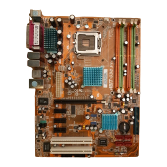
Page 7: Layout Diagram
Introduction 1-2. Layout Diagram User’s Manual... - Page 8 Chapter 1 Chapter 1 GD8 Pro GD8 Pro...
-
Page 9: Chapter 2. Hardware Setup
Hardware Setup Chapter 2. Hardware Setup Before the Installation: Turn off the power supply switch (fully turn off the +5V standby power), or disconnect the power cord before installing or unplugging any connectors or add-on cards. Failing to do so may cause the motherboard components or add-on cards to malfunction or damaged. 2-1. -
Page 10: Install Cpu, Heatsink And Fan Assembly
6. Use your left hand to hold the load plate, and use your right thumb to peel the cap off. 3. Use your right thumb on the bottom-right side of the load plate and lift it up to fully open position. GD8 Pro... - Page 11 Hardware Setup The cap plays an important role in protecting For detailed information on how to install your contact pins. In order to prevent bent pin, PUT heatsink and fan assembly, please refer to the ON the cap after operation or testing. instruction manual came packed with the heatsink and fan assembly you bought.
-
Page 12: Install System Memory
There are several methods of different DDR2 configurations depending on how the DIMMs are populated on each system memory channel: • [Single Channel]: only one channel is populated. Channel A Channel B Method DIMM1 DIMM2 DIMM3 DIMM4 512MB 512MB 512MB 512MB 512MB 512MB 512MB 512MB GD8 Pro... - Page 13 Hardware Setup • [Dual Channel Asymmetric]: both channels are populated, but each channel has a different amount of total memory. (Channel A≠Channel B) Channel A Channel B Method DIMM1 DIMM2 DIMM3 DIMM4 512MB 256MB 256MB 512MB 512MB 256MB 256MB 512MB 256MB 256MB 256MB...
-
Page 14: Connectors, Headers And Switches
This motherboard provides two power connectors to connect power supplier. NOTE: This 24-pin power connector “ATXPWR1” is compliant to the former 20-pin type. Pay attention to the orientation when doing so (Pin-11, 12, 23, and 24 should be left un-connected). GD8 Pro... -
Page 15: Fan Power Connectors
Hardware Setup (2). FAN Power Connectors These connectors each provide power to the cooling fans installed in your system. • CPUFAN1: CPU Fan Power Connector • SYSFAN1: System Fan Power Connector • AUXFAN1, AUXFAN2: Auxiliary Fan Power Connector WARNING: These fan connectors are not jumpers. DO NOT place jumper caps on these connectors. User’s Manual... -
Page 16: Cmos Memory Clearing Header
Pin 1-2 shorted (default): Normal operation. • Pin 2-3 shorted: Clear CMOS memory. WARNING: Turn the power off first (including the +5V standby power) before clearing the CMOS memory. Failing to do so may cause your system to work abnormally or malfunction. GD8 Pro... -
Page 17: Wake-Up Header
Hardware Setup (4). Wake-up Header These headers use a jumper cap to enable/disable the wake-up function. • PS2-PWR1: Pin 1-2 shorted (default): Disable wake-up function support at Keyboard/Mouse port. Pin 2-3 shorted: Enable wake-up function support at Keyboard/Mouse port • USB-PWR1: Pin 1-2 shorted (default): Disable wake-up function support at USB port. -
Page 18: Front Panel Audio Connection Header
To use the audio connector at rear panel, disconnect the extension cable, attach the jumpers back at pin 5-6, and pin 9-10 (default setting). Pin Assignment Pin Assignment MIC2 L AGND MIC2 R AVCC FRO-R MIC2_JD F_IO_SEN FRO-L LINE2_JD GD8 Pro... -
Page 19: Front Panel Switches & Indicators Headers
Hardware Setup 2-11 (6). Front Panel Switches & Indicators Headers This header is used for connecting switches and LED indicators on the chassis front panel. Watch the power LED pin position and orientation. The mark “+” align to the pin in the figure below stands for positive polarity for the LED connection. -
Page 20: Additional Usb Port Headers
These headers each provide 2 additional USB 2.0 ports connection through an USB cable designed for USB 2.0 specifications. Pin Assignment Pin Assignment Data0 - Data1 - Data0 + Data1 + Ground Ground (8). Internal Audio Connectors This connector connects to the audio output of internal CD-ROM drive or add-on card. GD8 Pro... -
Page 21: Serial Ata Connectors
Hardware Setup 2-13 (9). Serial ATA Connectors These connectors are provided to attach one Serial ATA device at each channel via Serial ATA cable. For more information on how to configure the function mode for SATA, please refer to the item “On-Chip SATA”... -
Page 22: Floppy And Ide Disk Drive Connectors
NOTE: Make sure to configure the “Master” and “Slave” relation before connecting two drives by one single ribbon cable. The red line on the ribbon cable must be aligned with pin-1 on both the IDE port and the hard-drive connector. GD8 Pro... -
Page 23: Pci Express X16 Slot
Hardware Setup 2-15 (12). PCI Express x16 Slot This slot is used to attach the next generation of graphics architecture. (13). PCI Express x1 Slots These slots are used to attach the next generation of I/O architecture. User’s Manual... -
Page 24: Back Panel Connectors
Line Out: Connects to the front left and front right channel in the 7.1-channel or regular 2-channel audio system. • LAN: Connects to Local Area Network. • USB1/USB2: Connects to USB devices such as scanner, digital speakers, monitor, mouse, keyboard, hub, digital camera, joystick etc. GD8 Pro... -
Page 25: Chapter 3. Bios Setup
BIOS Setup Chapter 3. BIOS Setup This motherboard provides a programmable EEPROM that you can update the BIOS utility. The BIOS (Basic Input/Output System) is a program that deals with the basic level of communication between processor and peripherals. Use the BIOS Setup program only when installing motherboard, reconfiguring system, or prompted to “Run Setup”. -
Page 26: Softmenu Setup
Chapter 3 3-1. SoftMenu Setup The SoftMenu utility is ABIT’s exclusive and ultimate solution in programming the CPU operating speed. All the parameters regarding CPU FSB speed, multiplier factor, the AGP & PCI clock, and even the CPU core voltage are all available at your fingertips. - Page 27 BIOS Setup Multiplier Factor: This item displays the multiplier factors for your CPU. Estimated new CPU Clock: This item displays the frequency sum up from the previous item [External Clock] and [Multiplier Factor]. N/B Strap CPU As: This item sets the external hardware reset strap assigned to MCH (Memory Controller Hub). The options are: [PSB533], [PSB800], and [By CPU].
-
Page 28: Standard Cmos Features
NOTE: The items “IDE Channel 3 Master/Slave” and “IDE Channel 4 Master/Slave” appear only when the item “On-Chip SATA” in the “On-Chip IDE Device” menu is set to [Enhanced Mode], or set to [Auto Mode] when SATA ports are connected with devices. GD8 Pro... - Page 29 BIOS Setup IDE HDD Auto-Detection: This item allows you to detect the parameters of IDE drives by pressing <Enter> key. The parameters will be shown on the screen automatically. IDE Channel 1 Master/Slave, IDE Channel 2 Master/Slave, Extended IDE Drive: When set to [Auto], the BIOS will automatically check what kind of IDE drive you are using.
-
Page 30: Advanced Bios Features
This item displays the total memory available in the system. 3-3. Advanced BIOS Features CPU L3 Cache: This item is used to enable the L3 cache (default setting), and appears only for certain CPU (Intel Pentium 4 processor with HT Technology Extreme Edition) that possesses L3 cache. GD8 Pro... - Page 31 BIOS Setup Hyper-Threading Technology This item is used to enable the functionality of the processor with Hyper-Threading Technology and will appear only when using such processor. The Hyper-Threading Technology helps your PC work more efficiently by maximizing processor resources and enabling a single processor to run two separate threads of software simultaneously, bringing forth greater performance and system responsiveness when running multiple applications at once.
- Page 32 CMOS before you can start up the system. But by doing this, you will have to reset all previously set options. MPS Version Ctrl For OS: This item specifies which version of MPS (Multi-Processor Specification) this motherboard will use. Leave this item to its default setting. GD8 Pro...
-
Page 33: Advanced Chipset Features
BIOS Setup Report No FDD For OS: When set to [Yes], this item allows you to run some older operating system without floppy disk drive. Leave this item to its default setting. Delay IDE Initial (Secs): This item allows the BIOS to support some old or special IDE devices by prolonging this delay time. A larger value will give more delay time to the device for which to initialize and to prepare for activation. - Page 34 Init Display First: This item selects whether to initiates from “PCI Express Slot” or “PCI Slot” first when system boots up. PEG Force X1: When set to [Enabled], this item forces the PEG port down to x1 mode. GD8 Pro...
-
Page 35: Integrated Peripherals
BIOS Setup 3-11 3-5. Integrated Peripherals On-Chip IDE Device: Click <Enter> key to enter its submenu: IDE Bus Master: This option enables or disables the IDE bus mastering capability under the DOS environment. On-Chip IDE-1 Controller: This item selects whether to enable or disable the IDE-1 controller. On-Chip SATA: This item determines the function for on-chip Serial ATA. - Page 36 IDE1 IDE1 Secondary SATA1 SATA3 None None None None Master Slave NOTE: This option is configurable only when the item [On-Chip SATA] is set to [Combined Mode]. SATA Mode: This item displays the variety modes for SATA mode. GD8 Pro...
- Page 37 BIOS Setup 3-13 On-Chip PCI Device: Click <Enter> key to enter its submenu: On-Chip USB Controller: This option enables or disables the USB controller. USB 2.0 Controller: This option enables or disables the USB 2.0 controller. USB Keyboard Support: This item allows you to select [BIOS] for using USB keyboard in DOS environment, or [OS] in OS environment.
- Page 38 [ECP+EPP]: Allows parallel port operation at ECP and EPP mode. EPP Mode Select: This item selects the EPP mode. ECP Mode Use DMA: This item selects the DMA channel of the parallel port. GD8 Pro...
-
Page 39: Power Management Setup
BIOS Setup 3-15 Onboard PCI Device: Click <Enter> key to enter its submenu: Network Controller : This option enables or disables the LAN controller. Invoke Boot Agent: This item allows you to use the boot ROM (instead of a disk drive) to boot-up the system and access the local area network directly. - Page 40 [1-31]: This option selects a date you would like the system to power-on. The system will power-on on the date set, and the time set in the “Time (hh:mm:ss) Alarm” item. Time (hh:mm:ss) Alarm This item sets the time you would like the system to power-on. GD8 Pro...
- Page 41 BIOS Setup 3-17 POWER ON Function: This item selects the way you want your system to power on. [Password]: Use a password to power on the system, select this option then press <Enter>. Enter your password. You can enter up to 5 characters. Type in exactly the same password to confirm, and then press <Enter>.
-
Page 42: Pnp/Pci Configurations
[Enabled]: MPEG ISA/VESA VGA cards work with PCI/VGA. [Disabled]: MPEG ISA/VESA VGA cards do not work with PCI/VGA. PIRQ_0 Use IRQ No. ~ PIRQ_7 Use IRQ No.: This item specifies the IRQ number manually or automatically for the devices installed on PCI slots. GD8 Pro... -
Page 43: Pc Health Status
This item sets the maximum TLP payload size for the PCI Express devices. 3-8. PC Health Status ABIT FanEQ Control: This item allows you to control the ABIT FanEQ by pressing the <Enter> key. FAN Fail Alarm Selectable: This item selects the fan that will be monitored for malfunction. -
Page 44: Load Fail-Safe Defaults
This option protects the BIOS configuration or restricts access to the computer itself. 3-12. Save & Exit Setup This option saves your selections and exits the BIOS setup menu. 3-13. Exit Without Saving This option exits the BIOS setup menu without saving any change. GD8 Pro... -
Page 45: Appendix A. Install Intel Chipset Software Utility
Install Intel Chipset Software Utility Appendix A. Install Intel Chipset Software Utility NOTE: Please install this Intel Chipset driver first after having installed the Windows operating system. The installation procedures and screen shots in this section are based on Windows XP operating system. - Page 46 Appendix A Appendix A GD8 Pro GD8 Pro...
-
Page 47: Appendix B. Install Audio Driver
Install Audio Driver Appendix B. Install Audio Driver The installation procedures and screen shots in this section are based on Windows XP operating system. For those of other OS, please follow its on-screen instruction. Insert the Driver & Utility CD into CD-ROM drive, it should execute the installation program automatically. - Page 48 Appendix B Appendix B GD8 Pro GD8 Pro...
-
Page 49: Appendix C. Install Lan Driver
Install LAN Driver Appendix C. Install LAN Driver The installation procedures and screen shots in this section are based on Windows XP operating system. For those of other OS, please follow its on-screen instruction. Insert the Driver & Utility CD into CD-ROM drive, it should execute the installation program automatically. - Page 50 Appendix C GD8 Pro...
-
Page 51: Appendix D. Install Usb 2.0 Driver
Install USB 2.0 Driver Appendix D. Install USB 2.0 Driver NOTE: To install the USB 2.0 Driver for Windows XP / Windows 2000, you have to download the latest SP2 (service pack 2) / SP4 (service pack 4) or later version first from Microsoft’s web site. User’s Manual... - Page 52 Appendix D Appendix D GD8 Pro GD8 Pro...
-
Page 53: Appendix E. Flashmenu (Bios Update Utility
ABIT FlashMenu is the most stable Windows-based BIOS flash available. No more worries from crashing. With one click of BIOS updating, ABIT users can flash their BIOS more easily and in less time. The installation procedures and screen shots in this section are based on Windows XP operating system. - Page 54 Appendix E GD8 Pro...
-
Page 55: Appendix F. Abit Eq (The Hardware Doctor Utility
ABIT EQ (The Hardware Doctor Utility) Appendix F. ABIT EQ (The Hardware Doctor Utility) ABIT EQ is a self-diagnostic system for PC based on motherboards designed and manufactured by ABIT Computer Corporation. It will protect PC Hardware by monitoring critical items of Power Supply Voltage, CPU &... - Page 56 Appendix F GD8 Pro...
-
Page 57: Appendix G. Troubleshooting (Need Assistance
Troubleshooting (Need Assistance?) Appendix G. Troubleshooting (Need Assistance?) Q & A: Q: Do I need to clear the CMOS before I use a new motherboard to assemble my new computer system? A: Yes, we highly recommend that you clear the CMOS before installing a new motherboard. Please move the CMOS jumper from its default 1-2 position to 2-3 for a few seconds, and then back. - Page 58 Sound Card Driver. Write down the Sound Card model, motherboard model, BIOS identification number on the technical support file (refer to main instructions), and describe the problem in the space provided. We will show you how to fill the “Technical Support Form”. GD8 Pro...
- Page 59 To fill in this “Technical Support Form”, refer to the step-by-step instructions given below: . MODEL: Note the model number given in your user’s manual. Example: GD8 Pro . Motherboard model number (REV): Note the motherboard model number labeled on the motherboard as “REV:*.**”.
- Page 60 ! Company Name: ) Phone Number: " Contact Person: # Fax Number: * E-mail Address: Model BIOS ID # Motherboard Model No. DRIVER REV OS/Application Hardware Name Brand Specifications IDE1 IDE2 IDE1 CD-ROM-Drive IDE2 System Memory ADD-ON CARD Problem Description: GD8 Pro...
-
Page 61: Appendix H. How To Get Technical Support
Also please make sure you have the latest drivers from your peripheral cards makers! 3. Check the ABIT Technical Terms Guide and FAQ on our Website. We are trying to expand and make the FAQs more helpful and information rich. Let us know if you have any suggestions. - Page 62 They should have reasonable return or refund policies. How they serve you is also a good reference for your next purchase. 6. Contacting ABIT. If you feel that you need to contact ABIT directly you can send email to the ABIT technical support department. First, please contact the support team for the branch office closest to you.
- Page 63 Unit 3, 24-26 Boulton Road, Stevenage, Herts SG1 4QX, UK Tel: 44-1438-228888 Fax: 44-1438-226333 E-mail: sales@abitcomputer.co.uk Germany and Benelux (Belgium, AMOR Computer B.V. (ABIT's European Office) Jan van Riebeeckweg 15, 5928LG, Venlo, Netherlands, Luxembourg), The Netherlands France, Italy, Spain, Portugal, Tel: 31-77-3204428 Greece, Denmark, Norway,...
- Page 64 Web Site: http://www.abit.com.tw 8. Reporting Compatibility Problems to ABIT. Because of tremendous number of email messages we receive every day, we are forced to give greater weight to certain types of messages than to others. For this reason, any compatibility problem that is reported to us, giving detailed system configuration information and error symptoms will receive the highest priority.
Need help?
Do you have a question about the GD8 Pro and is the answer not in the manual?
Questions and answers