
Related Manuals for Sears Kenmore PRO 401.40483800


Summary of Contents for Sears Kenmore PRO 401.40483800
- Page 1 Manual No: 46110808 SIDE BY SIDE REFRIGERATOR 401.40483800 CONFIDENTIAL INFORMATION – FOR INTERNAL USE ONLY Do not copy – Do not distribute to anyone other than a Sears Technician © 2008 Sears, Roebuck and Co.
- Page 2 KENMORE PRO Section 1. PRECAUTIONS BEFORE YOU BEGIN Read these instructions completely and carefully. WARNING SAFETY PRECAUTIONS • This refrigerator has 360° rotating casters. To prevent rolling or skidding while moving the unit, make sure to secure it firmly. • Due to the weight and size of this refrigerator, and to reduce the risk of personal injury or damage to the product, a minimum of four people are required to bring the unit into the home, and two people are required for proper installation.
- Page 3 WARNING USE OF ADAPTER PLUGS AND EXTENSION CORDS • Do not use extension cords for regular use of this appliance. This is a fire hazard, even if the cord is rated for appliance use. • If you cannot locate the refrigerator near an existing outlet, it is best to run a dedicated electrical line to service the refrigerator.
- Page 4 INSTALLATION SPACE INFORMATION ◆ ◆ After selecting an installation space: 1) Measure the door clearances to make sure the refrigerator can be moved though the house to the installation space. 2) Measure the installation area for proper ventilation and wall clearances as shown the illustrations* Below (Page 3, installation manual) here.
- Page 5 • The floor must be able to support the weight of the refrigerator and the food inside (1102lb or 500kg total). • The floor must be level so that the refrigerator does not vibrate or make noise. • Do not place the equipment in direct sunlight. •...
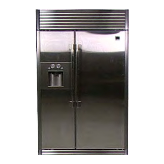
- Page 6 Section 2. Product Specifications Product Specifications 29.5 cu.ft Total 18.64 cu.ft Capacity Freezer Compartment 10.86 cu.ft Fridge Compartment 48” Width(inch) 84” Dimension Height(inch) 25.65” Depth(inch) 547lb Weight Rated V/Hz AC 115V / 60Hz 155W Motor Power Consumption 500W Heater Power Consumption Indirect Cooling Refrigerator Type HFC-134a...
- Page 7 Product Specifications BK190CL2C/E01 Part Number Compressor Inverter Starting Type Freol α -15 (Ester) Oil Charge Refrigerator Split Fin Type Evaporator Freezer Fin Cross Type Step Motor Valve DC14V/ Unipolar 1-2 Phase Excitation Method Condenser Forced or Natural Convection Drier Molecular Sieve XH-9 Freezer ID0.85 X L3300 4.4 Kg/㎠...
- Page 8 F- Defrost Heater AC 115V 300W, 44Ω(Sheath heater) F- Drain Heater On upon F-Defrost AC 115V 35W, 375Ω(Cord Heater) F - SUB Drain Heater AC 115V 10W, 1270Ω(Cord Heater) R- Defrost Heater AC 115V 110W, 120Ω(Heater Pipe) On upon R-Defrost R -Drain Heater AC 115V 30W, 440Ω(Cord Heater) AC 115V...
- Page 9 Product Dimensions DOOR 90 OPEN DOOR 130 OPEN 83.4”min 84”min 44” 52” 40.8” 42.9” 13.6” 20.3” 48” 47” 24.8” 25.6” 28.2” 84.2”max 84.8”max...
- Page 10 PART PART NAME CODE REMARKS DA61-01589A ANTI-TIP BRACKET Cap support filter DA99-00466A Filter DA29-00003B Valve fitting pu DA62-00305A...
- Page 11 Refrigeration Cycle COMPRESSOR SUB-CONDENSER PIPE DRIER FRE/REF/HOT PIPE REF CAPILLARY TUBE REF EVAPORATOR FRE CAPILLARY TUBE FRE EVAPORATOR REF EVAPORATOR FRE EVAPORATOR COMPRESSOR REF CAPILLARY TUBE FRE CAPILLARY TUBE(RED) DRIER CONNECTOR CAPILLARY FREEZER COMPARTMENT FRIDGE COMPARTMENT SUB-CONDENSER PIPE...
- Page 12 Cold Air Circulation FREEZER FAN FRIDGE FAN REF EVAPORATOR FRE EVAPORATOR FRIDGE COMPARTMENT FREEZER COMPARTMENT FRONT VIEW...
- Page 13 Section 3. ARRANGEMENT AND ADJUSTMENT 1. Machine Compartment Fan Motor Delay Function This refrigerator is programmed to control its temperature automatically in accordance with the ambient ● temperature. The Compressor Cooling Fan (Machine Compartment Fan) is controlled according to the ambient temperature. ●...
- Page 14 3) Defrost Function 1) Freezer Defrost depends on the accumulated run time. 2) With the initial power-on, defrost starts in both the refrigerator and freezer after 6 hours accumulated run time. 3) The defrost cycle is changed automatically from MIN 5 hours to MAX 10 hours. 4) The defrost cycle depends on the ambient temperature, the frequency of door opening, and the duration of door opening.
- Page 15 Details of Load Status Light Display by Position Items DISPLAY LED T r o u b l e s h o o t i n g FRIDGE SEGMENT The relevant segment LED comes on when the R- FAN HIGH operates. R-FAN HIGH FRIDGE SEGMENT...
- Page 16 7) Test Function (Forced Operation/Forced Defrost) ;This function is to test Comp operation. In case of Inverter Comp, RPM is changed depends on the running status. We only test following 3 cases instead of testing all the running RPM. To initiate the Test Function: 1) Press and hold the [Fridge Temp.] Control button and the [Rapid Ice] on the PANEL PCB at the same time and hold for 8 seconds.
- Page 17 8) Self-Diagnosis Function Self-Diagnosis during Initial Power On 1) When powering on, the Main PCB checks the temperature sensors for errors. 2) If a defective sensor is found, the relevant display LEDs will flash on and off at intervals of 0.5 sec. There will be no warning beep.
- Page 18 Details of Self-Diagnosis Light Display by Position Items DISPLAY LED Trouble shooting Remarks FRIDGE SEGMENT Displaying a defect when the R- Sensor Housing slip-out from the R-SENSOR Sensor temp is over 149℉(65℃) R-Compartment,Contact Failure,Wire Cut,Wire Short,Defective R-Sensor. or below -58℉(-50℃). FRIDGE SEGMENT Defrost Sensor Housing slip-out from the...
- Page 19 9) Option Setting Function This function is to compensate the temperature when the actual temperature is lower or higher than the setting temperature. Refrigerator temperature can be within the range of setting temperature with this temperature compensation. (This function only can be used when you can’t find out the root cause of the problem and unavailable to repair.
- Page 20 All the data for the Option is cleared before leaving the factory. all the setting values are “0” However,some units can have different setting values for the purpose of quality improvement during mass production. Please make sure to check the Quality Information. TO SET FREEZER LED DISPLAY FRIDGE LED DISPLAY...
- Page 21 ② Table for changing temperature in the R-Compartment Set Item FRIDGE TEMP SHIFT Position:FRIDGE 7-SEG DISPLAY Set Item Set Item Common Common FREEZER 7-SEG FREEZER 7-SEG 1℉ ↑ (compare with Standard Temp) Standard Temp 1℉ ↓ (compare with Standard Temp) 2℉...
- Page 22 Section 4. Remove/Replace Components for Service WARNING: Turn the refrigerator off before disassmbling any components. Description Page Description Page ❶ Machine Compartment Cover ❻ Lower Custom Panel of F-Compartment 24 ❷ Upper Custom Panel of F-Compartment ❼ Leg Cover ❸ Door Handle ❹...
- Page 23 WARNING: Turn the refrigerator off before disassembling any components. PART NAME DESCRIPTION FIGURE ① Remove the round Dispenser Tray. ② Remove a circled screw on the bottom from the Dispenser Cover. ③ Remove 2 fixing screws from the Dispenser Lamp Cover. DISPENSER- ④...
- Page 24 WARNING: Turn the refrigerator off before disassembling any components. PART NAME DESCRIPTION FIGURE ① Remove the lamp cover DISPENSER– by turning the 2 screws BULB counterclockwise. ② Replace the bulb. ① Remove the 7screws at the side. ② Remove circled 1 screw HANDLE at the upper section.
- Page 25 WARNING: Turn the refrigerator off before disassembling any components. PART NAME DESCRIPTION FIGURE ⑦ Remove the circled fixing screw for Water Line. FREEZER ⑧ Push the inner coupling using one hand and pull out Water DOOR Line from the coupling using the other hand.
- Page 26 WARNING: Turn the refrigerator off before disassembling any components. Interior Overview The descriptions of internal parts are illustrated in the photo below and refer to the pages below for disassembling each part. For the parts not illustrated in the photo, refer to the exploded view. Description Page Description...
- Page 27 WARNING: Turn the refrigerator off before disassembling any components. PART NAME DESCRIPTION FIGURE ① Hold the bottom of the left long slot with your hand, lift Ice Storage Bin up and pull forward to remove it. ① Flip the cover up and R-Compartment push it back to the –...
- Page 28 WARNING: Turn the refrigerator off before disassembling any components. PART NAME DESCRIPTION FIGURE ① Remove the Ice Storage Bin then lift up the cover of Freezer Storage to the direction of the arrow mark to remove. (Insert the spring into its seat when assembling it again.) ②...
- Page 29 WARNING: Turn the refrigerator off before disassembling any components. PART NAME DESCRIPTION FIGURE ② After removing the housing from the left wall and the sensor housing on the upper side,pull the evaporator Remove Housing cover out as shown in the photo.
- Page 30 WARNING: Turn the refrigerator off before disassembling any components. PART NAME DESCRIPTION FIGURE ① F-Compartment Evaporator –After removing the Fan Motor Ass’y as shown in the photo, remove the clamp F-Compartment screw holding the Evaporator – evaporator. Defrost ② Turn the evaporator over Heater/Bimet again to pull it out from its Fixing screw...
- Page 31 WARNING: Turn the refrigerator off before disassembling any components. PART NAME DESCRIPTION FIGURE ① Remove the two screws from under the auger motor. Remove auger motor and Pull the auger motor out from duct. ② Refer to the F-Compartment Interior Lamp to remove the lamp F-Compartment cover.
- Page 32 WARNING: Turn the refrigerator off before disassembling any components. PART NAME DESCRIPTION FIGURE ① Temperature Control Drawer – Refer to how to remove the Damper to remove the rear water Temperature cover and the connecting duct,remove the Fan Control and its trim from the retaining hook. If Drawer–Fan necessary, you can remove only the Fan clamp screw to replace the Fan.
- Page 33 WARNING: Turn the refrigerator off before disassembling any components. PART NAME DESCRIPTION FIGURE MACHINE ① Right figure displays the Machine Compartment. COMPARTMENT ① Open the Assy-Grille and remove Assy-cover comp. ② Remove gas struts from the stud by loosening ASSY-GRILLE, the clip of the strut GAS SPRING with a screw driver.
- Page 34 WARNING: Turn the refrigerator off before disassembling any components. PART NAME DESCRIPTION FIGURE ① Remove circled 2 screws. ② Pull out Condenser from PCB-HOUSING. PCB-HOUSING ※ Be careful do not change CONDE NSER the terminals during assembly. ① Remove the Cover Grill, remove the 3 welded sections.
- Page 35 WARNING: Turn the refrigerator off before disassembling any components. PART NAME DESCRIPTION FIGURE ① Remove the 2 screws over the Ice Maker and the power Water Supply Clip HEATER- core housing, pull the Ice WATER PIPE Maker Kit forward to remove. ②...
- Page 36 Section 5. Self Diagnosis Case Output Terminal ※ Test the terminals on the Terminal Block to check for voltage or operation related errors. The terminal layout is shown in the diagram.
- Page 37 AC INPUT POWER CORD F DEF HEATER & /60Hz 115V F DRAIN HEATER AC 115V R DEF HEATER & R DRAIN HEATER & OSCILLATOR ICE WATER PIPE HEATER POWER SUPPLY DIODE OPTION BUZZER CIRCUIT EEPROM RESET CIRCUIT INVERTER COMP SIGNAL CIRCUIT 12V / 5V DISPENSER HEATER...
- Page 38 Section 7. WIRING DIAGRAM...
- Page 40 Section 8. CIRCUIT DESCRIPTION 8-1. CONNECTOR ARRANGEMENT DESCRIPTION (MAIN) 1. F-DOOR S/W 1. F-FAN OP SIGNAL 1~2. DAMPER HEATER 1. C-FAN OP SIGNAL 2. R-DOOR S/W 2. F-FAN OP VOLTAGE 3~6. DAMPER MOTOR 2. C-FAN OP VOLTAGE 3. ICE ROUTE S/W1 3.
- Page 41 8-2. CONNECTOR ARRANGEMENT DESCRIPTION (INVERTER & SMPS) 1. COMP U PHASE INPUT AC 115V 2. COMP V PHASE 3. COMP W PHASE COMPRESSOR RPM SIGNAL COMPRESSOR 1. 5V 2. GND 3~4. 12V VOLTAGE INPUT AC 115V...
- Page 42 Section 9 Troubleshooting Sensors - Temperature/Resistance/Voltage Chart Temp. Resistance Temp. Resistance Temp. Resistance Voltage Voltage Voltage (℉) (㏀) (℉) (㏀) (℉) (㏀) -43.6 98.9 4.54 12.2 21.4 3.41 68.0 6.01 1.88 -41.8 93.7 4.52 14.0 20.5 3.36 69.8 5.79 1.83 -40.0 88.9 4.49...
-
Page 43: Table Of Contents
Troubleshooting Flow Charts 1. Unit Dead No Display 2 1 X X X X X X X 5 4 3 2 1 7 6 5 4 3 2 5 4 3 2 1 X 7 6 5 4 X X 1 TERMINAL BLOCK MAIN SWITCH... -
Page 44: Cn1
2. Unit Running No Display 2 1 X X X X X X X 5 4 3 2 1 7 6 5 4 3 2 5 4 3 2 1 X 7 6 5 4 X X 1 TERMINAL BLOCK... - Page 45 3. Unit Running Display Locked Unit Running Display Locked Pc Er or fault code 13 is a communication error Is Pc Er Check for fault blinking in codes using chart Display? in manual. If problem is between hinge and display, door Unplug CN6 from replacement Terminal Block and...
- Page 46 4. Compressor Not Operating Compressor Not Running 2 1 X X X X X X X 5 4 3 2 1 Compressor Put unit into Wait 5 minutes in 5 minute Forced Operation and recheck delay? 7 6 5 4 3 2 5 4 3 2 1 X 7 6 5 4 X X 1...
- Page 47 5. Fan Failure Codes...
-
Page 48: Cn2 Cn3
6. Refrigerator Not Cooling Freezer OK Refrigerator Compartment Not Cooling Freezer OK This is ruling out problems due to Door left open Drawer blocking door Measure temperature in Overloaded holding door open Put Unit into Self Fault code(s)? Compartment and Compare Door gasket not sealing Diagnosis with display temperature... - Page 49 7. Refrigerator Defrost Problem or Possible Fan Problem Troubleshooting Refrigerator Defrost Problem All the sensors are the same except for the length of wiring Causing Fan harness. Use sensor chart that shows correlation between Problem temperature, Vdc, and Resistance Allow compressor If above compartment temperature, to run at least 10 failed sensor...
- Page 50 8. Freezer Not Cooling Refrigerator OK Freezer Compartment This is ruling out problems due to Not Cooling Door left open Refrigerator All the sensors are the same except for the length of wiring Drawer blocking door harness. Use sensor chart that shows correlation between Overloaded holding door open temperature, Vdc, and Resistance Ice bin blocking door open Flapper...
- Page 51 9. Freezer Defrost Problem or Possible Fan Problem Troubleshooting Freezer Defrost Problem Causing All the sensors are the same except for the length of wiring Fan Problem harness. Use sensor chart that shows correlation between temperature, Vdc, and Resistance Allow compressor If above compartment temperature, to run at least 10 failed sensor...
- Page 52 10. No Water Dispensed No Water Dispensed Check Dispenser Switch Disconnect CN6 from Does ice terminal block and check dispense? continuity from P9 (gray) to P10 (white) when depressing switch Check for open or shorted wire Check for: harness from clogged filter Is Icemaker terminal block to...
- Page 53 11. Not Dispensing Ice Dispensing Ice/Augur Not Assuming Jammed Icemaker working OK and bucket has ice Check Dispenser Switch Disconnect CN6 from Does water terminal block and check dispense? continuity from P9 (gray) to P10 (white) when depressing switch Check for open or Check voltage shorted wire CN4 P7 (red)
- Page 54 12. Dispenser Light Not Working 2 1 X X X X X X X 5 4 3 2 1 7 6 5 4 3 2 5 4 3 2 1 X 7 6 5 4 X X 1 TERMINAL BLOCK...
- Page 55 13. Flapper Motor Not Working 2 1 X X X X X X X 5 4 3 2 1 7 6 5 4 3 2 5 4 3 2 1 X 7 6 5 4 TERMINAL X X 1 BLOCK...
-
Page 56: Cn1
14. Cubed Selected Get Crushed Ice Cube Selected Only Get Crushed (Green 2 1 X X X X X X X 5 4 3 2 1 LED On) This is referring 7 6 5 4 3 2 5 4 3 2 1 X 7 6 5 4 to the Green LED Check voltage... - Page 57 16. Door Alarm Does Not Sound 17. Door Alarm Does Not Shut Off...
- Page 58 18. Flapper Motor Runs Continuously 19. Compressor and Fans Not Operating – “OF” in both displays...
-
Page 59: 2 1 X
20. No Water in Icemaker 2 1 X X X X X X X 5 4 3 2 1 7 6 5 4 3 2 5 4 3 2 1 X 7 6 5 4 X X 1 TERMINAL BLOCK... -
Page 60: 6 5
Connector Circuits CN1 Line Filter/Main Switch The wiring diagram did not match the test model. Here is how the unit was wired. Notice CN1 is always live. C N 1 C N 2 C N 3 2 1 X C N 4 X X X X X X 5 4 3 2 1 C N 5... - Page 61 CN3 Refrigerator Low Voltage Circuits P1 Damper Heater P2-5 Damper Motor P6-Fresh Island Motor P7-Fresh Island Motor P8-F-Fan Motor F/G (feedback) P9-F-Fan Motor W+ P10-DC Common P11-Refrigerator Compartment Sensor P12-Refrigerator Defrost Sensor C N 1 C N 2 C N 3 2 1 X C N 4 X X X X X X...
- Page 62 CN5 Fresh Island (Convertible Drawer) P14-Fresh Island Sensor P15-Fresh Island Sensor C N 2 C N 3 2 1 X C N 4 X X X X X X 5 4 3 2 1 C N 5 C N 6 C N 7 7 6 5 4 3 2 5 4 3 2 1...
- Page 63 CN7 Compressor Compartment Low Vo ltage P1-P5 3 Way Valve P6-Freezer Door Switch P7-Refrigerator Door Switch P10-Condenser Fan Motor F/G (feedback) P11-Condenser Fan Motor W+ P12-DC Common C N 1 C N 2 C N 3 2 1 X C N 4 X X X X X X 5 4 3 2 1 C N 5...
- Page 64 CN9 Compressor Compartment & Door High Voltage P1-AC Common P2-Comp ressor Overload P3-Comp ressor Overload P4-Water Valve/Icemaker P6-Di spenser Heater Geared Motor Cover (Flapper Motor) P8-Water Valve/Wa ter Dispenser P9-Dispenser Light P10-P12-Compressor Wind ings Icemaker Connector Icemaker CN GRN/YEL - Ground YEL –...
- Page 65 iring Diagram...
- Page 68 Universal Keywords: Div46 Samsung Mechtech Document Specific Keywords: Side by Side Refrigerators Document Name: 46110808 Subject: Service Manual Source Number: 401 Date: 110708 Models: 401.40483800 40140483800...
Need help?
Do you have a question about the Kenmore PRO 401.40483800 and is the answer not in the manual?
Questions and answers
Need the housing unit for water filter for my Kenmore Pro model 401.40483800, serial no. A00843F2B000765
The housing unit for the water filter is located at the left back of the refrigerator. To access it, turn off the water supply, remove the cover grill, and then remove the wire housing of the water valve.
This answer is automatically generated
Kenomore pro side by side fridge freezer model 401.40483800 issues. Freezer has water that leaks some where below icemaker and runs down the back of the freezer causing ice buildup
Common issues with the Kenmore Pro side-by-side fridge freezer model 401.40483800 that can cause water to leak below the icemaker and lead to ice buildup include:
1. Freezer defrost problems – If the defrost sensor fails, the defrost heater may not activate, causing ice buildup that can melt and leak.
2. Faulty fan – A fan problem may prevent proper air circulation, leading to ice accumulation and water leakage.
3. Drain heater issue – If the drain heater is not working, water from defrost cycles may not drain properly and can freeze or leak.
These issues can cause water to collect and freeze below the icemaker, leading to ice buildup and leakage.
This answer is automatically generated
I would like to clean the coils on my refrigerator.Where are the coils located that will need to be vacuumed?
My kenmore pro 40140483800 runs and comes up to temp then comp shuts down and will not start I have to shut it down to restart