
Related Manuals for Air-Vac ONYX29


Summary of Contents for Air-Vac ONYX29
- Page 1 ONYX29 User Manual #0029.00.900 Series 7, Revision 2.0 High Performance Automation Rework...
- Page 2 ONYX29 User’s Manual 0029.00.900...
-
Page 3: Table Of Contents
ONYX29 User’s Manual TABLE OF CONTENTS COPYRIGHT ..............................7 TERMS OF DELIVERY ............................. 9 DECLARATION OF CONFORMITY ....................... 11 INTRODUCTION ............................. 13 ..............................13 ELCOME ......................14 ESIGNATED USE OF THE ACHINE GENERAL SAFETY INSTRUCTIONS ......................15 ........................15 ASIC... - Page 4 ONYX29 User’s Manual 10.3 ............................. 40 ACKING 10.4 ) ................40 EQUIREMENTS ALSO SEE ACILITY EQUIREMENTS 10.5 .......................... 41 ACILITY EQUIREMENTS 10.6 ): A ..................... 42 ORKSTATION OPTIONAL SSEMBLY 10.7 ONYX M ...................... 45 NSTALLATION OF THE ACHINE 10.8 ......................46...
- Page 5 ONYX29 User’s Manual 15.1.1 ........................100 ACHINE AINTENANCE 15.1.2 ........................101 AINTENANCE 15.1.3 ......................102 ORCE ENSOR AINTENANCE 15.1.4 ................102 ACHINE PERATOR ANEL AINTENANCE 15.1.5 ............................ 103 ISION 15.1.6 ..........................104 15.2 ....................106 PPER EATING LEMENT EPLACEMENT 15.3 : .........................
- Page 6 ONYX29 User’s Manual 0029.00.900...
-
Page 7: Copyright
Copyright Operating Instructions The information contained in this Operating Instructions is the property of Infotech AG/Air-Vac Engineering and shall not be reproduced or published to a third party or in part without prior written approval of Infotech AG/Air- Vac Engineering. - Page 8 ONYX29 User’s Manual 0029.00.900...
-
Page 9: Terms Of Delivery
Installation work will be charged separately, unless agreed upon otherwise. IV. Retention of Ownership Air-Vac retains ownership of its delivery until the invoice has been paid in full and is authorizes under its own onus to register the reservation with the responsible registry. - Page 10 ONYX29 User’s Manual 0029.00.900...
-
Page 11: Declaration Of Conformity
ONYX29 User’s Manual Declaration of Conformity 0029.00.900... - Page 12 ONYX29 User’s Manual 0029.00.900...
-
Page 13: Introduction
ONYX29 User’s Manual Introduction Notes and Warnings This manual contains safety instructions wherever these are required or prescribed. These instructions are divided into two categories as follows: Note A note describe special actions, procedures, instructions and information that are relevant to the subsequent section or step. -
Page 14: Designated Use Of The Machine
ONYX29 User’s Manual Designated use of the Machine The ONYX 29 Series 7 machine provides the capability to semi-automated removal, site cleaning and soldering advanced technology components such as BGA's, CSP's, Flip Chip, Micro-Discretes, surface mount connectors and fine pitch QFP's as well as traditional leaded devices such as PLCC's, SOIC's and sockets. -
Page 15: General Safety Instructions
ONYX29 User’s Manual General Safety Instructions Basic Safety Instructions In addition to the safety instructions in this document, the following guidelines must be observed to prevent personal injuries in general: Warning Because strong magnetic fields are associated with the system motor coils and magnet assembly, persons having active implants (pacemakers, etc) or having any other ferromagnetic products are not qualified and are not allowed either to operate the equipment or enter within a 0,5m perimeter around the system. - Page 16 ONYX29 User’s Manual Note Read this manual carefully before you operate, service or repair the machine. The machine may only be operated by qualified personnel who have received an appropriate training. When cleaning parts and peripherals of the machine, use only the sub-stances recommended. When maintaining and servicing the machine, use only the tools admitted therefore.
-
Page 17: Machine Warning Labels
ONYX29 User’s Manual Machine Warning Labels The following warning labels were used on the machine "ONYX 29 Series 7": Warning Each removed or defective warning label on the machine "ONYX 29 Series 7" must be replaced immediately. 0029.00.900... - Page 18 ONYX29 User’s Manual Warning of magnetic field Warning labels on the machine: • IP-500 Y-Axis left side in the back • IP-500 Y-Axis left side in the front • IP-500 X-Axis left side • IP-500 X-Axis right side This warning label indicates areas with strong magnetic fields.
-
Page 19: Airborne Noise Emitted
ONYX29 User’s Manual Warning of laser Warning labels on the machine: • In the front of the vision system This label indicates the danger of laser beams. Lasers generate a very intensive, strong bundled beam. The intensive light beam can especially harm the eyes and the skin. - Page 20 ONYX29 User’s Manual 0029.00.900...
-
Page 21: Specifications
ONYX29 User’s Manual Specifications 0029.00.900... -
Page 22: General Specifications
ONYX29 User’s Manual General Specifications Dimensions and Weight Width 823 mm Depth 821 mm Height 951 mm 773 mm without hose Weight 140 kg 308 lbs. Weight with Packaging 200 kg 441 Ibs. Electrical 3-phase power U (Voltage) 3 x 400/ 230 VAC... -
Page 23: Semi-Automated Soldering System
ONYX29 User’s Manual Semi-Automated Soldering System High end platform Precision force sensor table ManualMotion Interface for up to 4-pre-heater ports 4 Thermo couple ports (max. up to 8) Field illumination Z-axis 150 mm (OBC 30 up to OBC 70) Advanced solder head... -
Page 24: Interface For Preheater Ports
ONYX29 User’s Manual Interface for Preheater Ports • Includes 4 SSR relays and connector ports to connect 4 pre-heaters. Thermo Couple Modules • ManualModule with 4 thermocouple ports (standard) • Per default: TC # 1 is used for the overboard temperature... -
Page 25: Advanced Solder Head
ONYX29 User’s Manual Advanced Solder Head • Includes the advanced head pneumatics which is located in the platform and all the controls and pneumatics in the head interface • Hot gas system with 2 KW at 230 VAC heating source, temperatures up to 450 °C (internal 750 °C) -
Page 26: Nitrogen Gas Flow
ONYX29 User’s Manual Nitrogen Gas Flow Nitrogen gas flow with an additional pneumatic maintenance unit is installed which allows connecting a second gas source, in most cases this second gas is nitrogen. It is being used when lead free soldering processes are being performed. -
Page 27: Preheater
ONYX29 User’s Manual 7.13 Preheater Different pre-heaters with one- or multiples zones (up to4) can be used with the ONYX 29 Series 7. The temperature of each zone is program controlled, using a temperature sensor inside each pre-heater zone and a Solid State Relays (SSR) mounted inside the base of the system. -
Page 28: Board Carrier
ONYX29 User’s Manual Warning The same amount of time a preheater is being operated above the continues temperature limit, it has to be operated below the continues temperature limit. Using the pre-heaters over the given peak temperatures has to be limited to short pre-heat stages only. It is the operators responsibility to limit the high temperatures. -
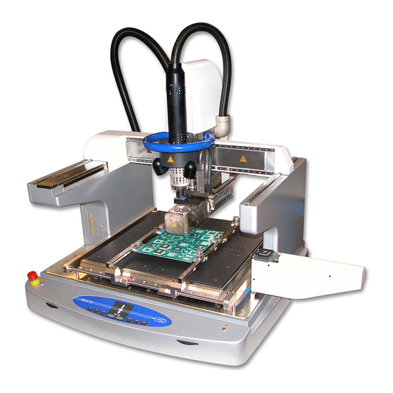
Page 29: Machine Overview And Options
ONYX29 User’s Manual Machine Overview and Options Note The machine layout may be custom specific any may appear different. The here displayed machine layout describes the Standard Hot Gas system. Item A, B and C: Identifies the board carrier and support features The board carrier has two fixed (A) support arms and two adjustable rails (B) to hold the board. - Page 30 ONYX29 User’s Manual The board carrier pivots upward to allow access to the underside of board. This feature simplifies board support positioning. It is important to position board supports clear of any bottom side components. Supports should be directly in contact with the board.
-
Page 31: Peripherals Overview Of The Standard Hot Gas System
ONYX29 User’s Manual Peripherals Overview of the Standard Hot Gas System Waffle Feeders • This position defines component à nozzle feeding device. • Waffle Feeder 2" by 2" or 4" by 4" (multiple components – rows x columns). • Universal component insertion tray for single component. -
Page 32: Site Cleaning System
ONYX29 User’s Manual 8.2.2 Site Cleaning System Objective: • Fully automated removal of residual site solder without damaging the pads or solder mask. Eliminates the need for traditional solder iron/solder wick process and associated issues (ie. manual intervention, mechanical contact of pads). -
Page 33: Board Cooling System
ONYX29 User’s Manual 8.2.4 Board Cooling System Objective: • Provides controlled cool down of both the device and assembly to effectively manage time-over-reflow and to facilitate handling of the assembly after rework. How It Works: • High laminar flow of cool air is directed between the bottom heater and the assembly, providing rapid cooling. -
Page 34: Paste-On-Device Micro Stencil Adapter
Pasted device in stencil is placed in micro stencil adapter, which is used in conjunction with the component shuttle to pick the pasted device. Notes Of Interest: • Air-Vac does not supply the component-specific micro stencils. Recommended supplier is Mini Micro Stencil (760-591-3804). Photo: •... -
Page 35: Direct View Camera & Mount Assembly
Camera/mount assembly. • Close-up view of BGA spheres. 8.2.10 Four (4) Additional Thermocouple Ports Objective: • Four (4) additional TC channels (total of 8) provides additional monitoring capability for advanced process development applications. The ONYX29 includes four (4) TC channels. 0029.00.900... -
Page 36: Fume Extraction Manifold
ONYX29 User’s Manual 8.2.11 Fume Extraction Manifold Objective: • Removes flux vapors from the work environment for operator health and safety. Exhaust • Includes: Manifold • Fume extraction manifold and hose assembly. Notes Of Interest: • Requires connection to a central exhaust or self-contained filtering system. -
Page 37: Visualmachines
ONYX29 User’s Manual VisualMachines™ The VisualMachines™ Software is used to support the ONYX 29 Series 7 processes, removal, site cleaning and soldering. The base software VisualMachines™ is designed to put the focus on the application, not the programming. It is an object oriented, modular software environment that enables rapid implementations of complex motion, vision and process control modules. - Page 38 ONYX29 User’s Manual 0029.00.900...
-
Page 39: Installation
ONYX29 User’s Manual Installation 10.1 Transport The machine must be transported in a temperature and humidity-controlled environment. The temperature range shall be within -20 °C to 50 °C. The relative humidity must be less than 60% (these data don’t correspond to the operation conditions). -
Page 40: Re-Packing
ONYX29 User’s Manual 10.3 Re-Packing If the machine has to be shipped again, the original transport locks and the original packaging have to be used. Contact the supplier, if the transport locks or the packaging is not available. Insufficiently protected and packed machines can be damaged during the transport. In this case the warranty will be limited. -
Page 41: Facility Requirements
ONYX29 User’s Manual 10.5 Facility Requirements Electrical: • Machine Power: 208 VAC, 50/60 Hz, 3-phase, 25 A (max). 6’ of 12/4 power cord supplied. No plug supplied with system. • Monitor Power: (208V) - Provided by convenience plug on machine. -
Page 42: Workstation (Optional): Assembly
ONYX29 User’s Manual 10.6 Workstation (optional): Assembly 36” x 60” ESD Bench 0029.00.900... - Page 43 ONYX29 User’s Manual Monitor Stand Nozzle Holder 0029.00.900...
- Page 44 ONYX29 User’s Manual Triple Locking Drawer CPU Holder 0029.00.900...
-
Page 45: Installation Of The Onyx Machine
ONYX29 User’s Manual 10.7 Installation of the ONYX Machine Note Floor loading capacity of 500 kg/m2 (installation specifications, common for industrial applications, concrete material, no raised floor). Before the machine "ONYX 29 Series 7" can be installed on its place, the machine table or a strong lab bench with a flat and horizontal surface must be installed. -
Page 46: Removing The Transport Locks
ONYX29 User’s Manual 10.8 Removing the Transport Locks Remove two screws. After these two screws are removed, the X-axis can be moved carefully to the right side. Make sure not to move the Y-axis during this moment because the linear scale of the Y-axis can be damaged. -
Page 47: Install The Preheater When Available
ONYX29 User’s Manual Note Put the safety bracket with the longer screws and the buffer replacement screw into a safe location. It will be used each time the system is being moved. Move the X-axis and the Y-axis from one end to the other end, then move both axis to about the center location. -
Page 48: Electrical Installation
ONYX29 User’s Manual 10.10 Electrical Installation Warning Only qualified personnel may work on the peripherals with low voltage devices. Country specific prescriptions must be considered. While working in the low voltage area, make sure to have another person present who knows the machine and can apply first aid. - Page 49 ONYX29 User’s Manual Electrical Supply 3 x 208 V /120 VAC (3PNE) 60 Hz 3 Phasen 16 A The external 3 phase main power cable has to be conducted through the large terminal. Depending on the cable cross-section some rubber distance rings have to be removed inside the terminal.
-
Page 50: Heater Phase Detection
ONYX29 User’s Manual On the side of the communication interface, the network cable (Ethernet) is plugged into the RJ45 socket (Machine), the other end is connected to the computer. On the side of the communication interface the camera cable is plugged into the RJ45 socket (Vision), the other end is connected to the computer. -
Page 51: Power On And Off
ONYX29 User’s Manual Power On and Off The several steps are listed below and described in detail in the following sections: • Turn on the main power switch • Turn on the control power switch • Turn on the computer (PC) •... - Page 52 ONYX29 User’s Manual Turn on the control power switch The control power switch is located on the front right side. Turn on the computer (PC) Switch on the monitor, the PC and load the operating system Windows. 0029.00.900...
- Page 53 ONYX29 User’s Manual VisualMachines™ Software Note Wait until the PC has loaded the windows operating system. This may take some minutes. As soon as the Windows operating system has been loaded, double click the Icon VisualMachines™ and the software will be started.
-
Page 54: Power Off
ONYX29 User’s Manual 11.2 Power Off To turn off the machine, follow the turn on sequence in reverse order: • Ending of the production • Press E-stop • Close the VisualMachines™ application • Turn off the computer (PC) • Turn off the control power switch Note The VisualMachines™... -
Page 55: Phase Detection
ONYX29 User’s Manual 11.4 Phase Detection Each time a machine is being connected to a new power source, the phase detection program must be executed. This is important, as all the heaters are calibrated exactly based on a given phase shift. If the phase shift is not as configured, then the controlling of the heaters will not work properly. -
Page 56: Operator Panel
ONYX29 User’s Manual 11.5 Operator Panel Start Starting a program for execution. This button has the same function as the Start button in the Execution View and of the foot switch (optional). A program can be executed only when it is loaded and selected. -
Page 57: Program Execution
ONYX29 User’s Manual Program Execution Note For accurate software descriptions and software help use the online help within the software VisualMachines™. 12.1 Execution View & Main Execution After starting VisualMachines™, the Execution View is opened automatically. Otherwise the Execution View is opened by clicking the Execution button on the Views tab. -
Page 58: Program Header
ONYX29 User’s Manual 12.1.1 Program Header The header shows the name and the description of the selected program. If no program is selected, it will display "No Program…" Quick Select button will open a submenu with all loaded programs. Selecting a program from the pull-down list will directly assign it to the execution so that it can be started. -
Page 59: Program Error Control
ONYX29 User’s Manual 12.1.2 Program Error Control The Program Error Control gets always enabled when there is an error occurring during the program execution. The user can make decisions how to continue by clicking the following buttons: Resume button will go on with the next process in the loaded program... - Page 60 ONYX29 User’s Manual 0029.00.900...
-
Page 61: Master Program Execution
ONYX29 User’s Manual Master Program Execution Note For accurate software descriptions and software help use the online help within the software VisualMachines™. 13.1 Operator Access Level To process removal, site cleaning and soldering on the ONYX 29 Series 7 the user access level is divided into the Operator and the Technical Operator. -
Page 62: Master Program
ONYX29 User’s Manual 13.2 Master Program Note The Master Program (Template Program) is being modified continuously and enhanced in order to cover as many soldering applications as possible using practical experience. The process sequence varies, depending on different machine configurations. For these reasons the following pictures and descriptions may appear different to the installed programs. -
Page 63: Select Or Copy Part Types (Direct Access)
ONYX29 User’s Manual 13.2.2 Select or Copy Part Types (Direct Access) Operator may skip this section. Once the start button has been selected, then the Technical operator is allowed to select or change the Part Type to be processed and change the thermo profile parameters associated with it. - Page 64 ONYX29 User’s Manual The Part Type Dimensions are being displayed and can be changed for the current production run. If a part type other than the Master Part Type is being selected, the dimensions should not be changed. In this case a copy of the part type record should be done instead, it can then be renamed and the dimensions can be changed.
- Page 65 ONYX29 User’s Manual Profile Graph The Profile Graph shows the set Temperature/Time diagram of the selected profile over the defined stages. The pink line defines the bottom heater temperatures over time (pre-heater), the red line defines the top heater temperatures over time (hot gas heater). Bottom heaters show always a rectangle profile. It is a slow acting heating device and does not exactly follow the selected profile.
- Page 66 ONYX29 User’s Manual Board Temperature Process Sensor The Board Temperature Process Sensor menu allows selecting max board temperatures surveillance process. If the checkbox Enable Max. Board Temperature Surveillance is set active, then a thermo couple can be selected which will protect the board overheating. If the bottom heater temperature is set too high, then the board may get too hot.
- Page 67 ONYX29 User’s Manual Stage Defines the profile stage, normally Pre-heat, Soak, Ramp, Reflow and Cooldown. Time [sec] The time of the stage in seconds. If the trigger is set to a temperature, then the time has a secondary function. If the temperature is reached before the time, then the stage time is shortened, or if the temperature is not yet reached, then the stage time is being enlarged automatically.
-
Page 68: Select Process List
ONYX29 User’s Manual 13.2.3 Select Process List Once the start button has been selected, then the Operator is allowed to select the process list of the selected Part. The board is displayed as a green image. The Master program shows a large board, the maximum possible 508 x 508 mm board. -
Page 69: Initialization Process Steps
ONYX29 User’s Manual 13.2.5 Initialization Process Steps Park (Robot) All axes of the robot are automatically moving to the defined park positions. This allows having access to the board carrier. This step is executed automatically and does not need any operator attention. -
Page 70: Completion Process Steps
ONYX29 User’s Manual 13.2.6 Completion Process Steps Stop Heating (Pre-Heater) The pre-heaters are being switched off, if the optional board cooling is installed, it is being activated automatically. This step is executed automatically and does not need any operator attention. -
Page 71: Part Removal Process Steps
ONYX29 User’s Manual 13.2.7 Part Removal Process Steps A soldered part must be removed from a board. For that process, the Part-Removal process is being setup as a template within the Master program. During the Part-Removal process, the nozzle is being visually aligned over the part to be removed. - Page 72 ONYX29 User’s Manual Control Heating (Hot Gas Tool) Because the vision unit will be used in the next step, this control heating process makes sure the top heater is switched off. This step is executed automatically and does not need any operator attention.
- Page 73 ONYX29 User’s Manual Interactive Soldering The interactive soldering page is shown in Training mode. In this mode the arrows on top of the table are active. For the Operator access level these buttons are inactive and cannot be used. When a...
- Page 74 ONYX29 User’s Manual Shows the remaining time of the actual profile stage Top heater (Hot gas system) temperature and gas flow Preheater temperature Thermocouple 1 (Board) Thermocouple 2, 3 and 4... Optional up to 8 (NC = not connected) Optional process temperature sensor...
- Page 75 ONYX29 User’s Manual Select the Save as… button to open a new Profile Name window. It is possible to enter a new name. Click the OK button to store the profile under a new profile record in the database. Select the Export csv… button to export the data of the profile together with the collected statistical data. This exported data can be edited using Microsoft Excel.
-
Page 76: Part Site Cleaning Process Steps
ONYX29 User’s Manual 13.2.8 Part Site Cleaning Process Steps After a part has been removed from a board, the site must be cleaned from the rest solder. For that process, the Part-Site cleaning process is being setup as a template within the Master program. - Page 77 ONYX29 User’s Manual Place Position Teach (Vision Unit) The Position on the board where the process shall be executed must be defined. If the position is already set from the previous program execution, then the teach process can be skipped as the ONYX 29 Series 7 uses closed loop axis and stores the process positions in databases.
- Page 78 ONYX29 User’s Manual Control Heating (Hot Gas Tool) The top heater is activated with the idle temperature and the idle flow level using air. This control heating process makes sure the top heater is switched off. This step is executed automatically and does not need any operator attention.
-
Page 79: Part Soldering Process Steps
ONYX29 User’s Manual 13.2.9 Part Soldering Process Steps A part must be soldered to a board. For that process, the Part-Soldering process is being setup as a template within the Master program. During the Part-Soldering process the part is being acquired and visually overlaid over the placement site. - Page 80 ONYX29 User’s Manual Move (Robot) The Master Program is being setup, that the part is manually loaded to the nozzle. For that reason, the nozzle is being moved to the front right position for easier access. If a feeder is setup, then this Move process can be ignored.
- Page 81 ONYX29 User’s Manual Select the Resume button after the alignment process is completed and the next process will be executed. Select the Skip button to move the vision system to the next corner. If the part is smaller than the selected field of view (FOV), then the entire component is shown and the Skip button has no effect.
- Page 82 ONYX29 User’s Manual The first step in the alignment process should be to align the rotation of the part. Use the center buttons on the operator panel to rotate the Theta axis with the part on the nozzle. During rotating the part, check the live video until the images appear parallel. It is important to have the two images parallel before starting to align the X/Y axes.
- Page 83 ONYX29 User’s Manual Operator Message (General Processes) The operator is prompted to manually put flux onto the place location. After the site is properly fluxed, select the Resume button. Place (Robot) The Z-axis moves automatically with the part on the nozzle above the location on the board. This step is executed automatically and does not need any operator attention.
- Page 84 ONYX29 User’s Manual Selecting this button allows skipping to the next stage. This button is available in the Training mode. It shall be used only during debug or setup phases. In normal operation it should be avoided to interrupt active soldering stages.
- Page 85 ONYX29 User’s Manual Inspection (Interactive Soldering) The executed profile during the interactive soldering process is being re-called and displayed. This inspection step is being processed when the Technical Operator has modified the interactive soldering profile during the execution, or when the Inspection mode is activated.
- Page 86 ONYX29 User’s Manual 0029.00.900...
-
Page 87: System Calibration
ONYX29 User’s Manual System Calibration The whole system is calibrated and functioning. This chapter contains some explanations for a better understanding of the machine. Periodical maintenance tasks can be found in chapter "Preventive Maintenance". Note For detailed software descriptions please use the "Online Help" of the VisualMachines™ software. -
Page 88: Robot Coordinate Band
ONYX29 User’s Manual 14.1.2 Robot Coordinate Band It is possible to open the Robot Coordinate Band through the Tools pull down menu. The band displays the current robot position of the TCP (Tool Center Point) of the head (including any tool/nozzle offsets):... -
Page 89: Advanced Jogging
ONYX29 User’s Manual 14.1.3 Advanced Jogging Use this to move the robot axes using two different jogging methods. One method is to move the axes step by step and the other method is to move the axes freely by pointing to the target position using the mouse cursor. -
Page 90: Teaching Positions
ONYX29 User’s Manual Step Move Use the step move buttons to move the corresponding axis step by step in the desired direction. The Linear Increment defines the linear distance for the step moves. This value affects directly the step distance for the jogging buttons in the Robot Coordinate Band (see the section before). -
Page 91: Calibration View
ONYX29 User’s Manual 14.2 Calibration View This section can be skipped for all Operators and Technical Operators. It is necessary to have the access level of Maintenance or higher to have access to the Calibration View and its functions. The Calibration View is opened by clicking the Calibration button on the Views tab. The Calibration View shows the machine configuration in a hierarchical tree structure. -
Page 92: Axes Calibration
Calibrates only the Theta-Axis, if present 14.2.3 Temperature Sensor and Thermo Couple Calibrations The ONYX29 Series 7 comes with several temperature sensors, depending on its configuration. Possible sensors: • Up to 8 thermocouples type K (standard 4) • Up to 4 temperature sensors PT100 of the Pre-heaters •... -
Page 93: Flow Rate Verification
14.3 Flow Rate Verification Note The ONYX29 Incorporates a precision mass flow controller to regulate the hot air flow. The flow of this device is verified prior to shipment on ONYX units by the manufacturer and does not need adjustment. -
Page 94: Hot Gas Tool Temperature Verification
14.4 Hot Gas Tool Temperature Verification Tools required: NCAL1 Temperature Nozzle 1. Open the temperature verification profile in the Air-Vac directory. - Go to Execution; Open Program folder; Open AV folder; - Select “Temperature Calibration Check – NCAL1 <date code>.itp”... -
Page 95: Hot Gas Tool Calibration
ONYX29 User’s Manual 14.5 Hot Gas Tool Calibration Tools required: NCAL1 Temperature Nozzle 1. Open the temperature verification profile in the Air-Vac directory. - Go to Execution; Open Program folder; Open AV folder; - Select “Temperature Calibration Check – NCAL1 <date code>.itp”... - Page 96 ONYX29 User’s Manual 0029.00.900...
-
Page 97: Preventive Maintenance
ONYX29 User’s Manual Preventive Maintenance The preventive maintenance on the machine "ONYX 29 Series 7" must be done periodically. The warranty can only be granted if the preventive maintenance has always been performed according to instructions and plan. Machine Maintenance Activity... - Page 98 ONYX29 User’s Manual 15.1.1 X-Y Axes Encoder Scale Cleaning Instructions Supplies required: Denatured Alcohol and Kimwipes® cleaning wipes. • When cleaning the encoder scale, wet the surface with the Denatured Alcohol and allow the alcohol to loosen the dirt (or evaporated flux solutions) before wiping.
- Page 99 ONYX29 User’s Manual 15.1.2 V ACUUM FILTER The ONYX 29 assembly head vacuum uses an inline filter. The filter is located under the back cover of the head. If the process includes heavy evaporating flux, then the filter must be replaced on a regular base.
-
Page 100: Maintenance View
ONYX29 User’s Manual 15.2 Maintenance View This section can be skipped for all Operators and Technical Operators. It is necessary to have the access level of Maintenance or higher to have access to the Maintenance View and its functions. The Maintenance View is opened by clicking the Maintenance button on the Views tab. -
Page 101: Head Maintenance
ONYX29 User’s Manual 15.2.2 Head Maintenance The head maintenance page displays information of the current attached tool. Selecting another tool entry in the Current mounted Tool list and clicking OK does change the tool in VisualMachines™. Warning Changing the current mounted tool does not change it physically. Please make sure that the linked tool does correspond to the mounted one. -
Page 102: Force Sensor Maintenance
ONYX29 User’s Manual 15.2.3 Force Sensor Maintenance The force sensor maintenance page displays the current load on the force sensor table. Zero Force Sensor button does reset the force sensor to 0 N. The Force Threshold field can be used to check the functionality of the system. -
Page 103: Vision Unit
ONYX29 User’s Manual 15.2.5 Vision Unit The Maintenance view of the Vision unit peripheral can display live streaming video. It allows changing light unit parameters and also camera features. All signals and motion axis can be operated in this menu page. Values set in this page have no effect during program execution. -
Page 104: Hot Gas Tool
ONYX29 User’s Manual • The Apply Camera Default button sets all features back to the last saved state. • Clicking on the Save Camera Default button does save the current feature setting as the default setting. These values will be used to initialize the camera at each start of VisualMachines™. - Page 105 ONYX29 User’s Manual Hot Air Flow Control • Current Flow shows the current hot air flow • Hot Flow Set Point for the tool • Heater by-pass (fast cool down) switches the valve that the heater element is by passed for rapid cool down processes.
-
Page 106: Upper Heating Element Replacement
ONYX29 User’s Manual 15.3 Upper Heating Element Replacement 1. Take off the white Cover. White Cover Screw 2. Take off the Top Cover by… Top Cover 3. Loosening the two set Screws and take off the Plate. Plate Set Screw... - Page 107 ONYX29 User’s Manual 4. Loosen the three Screws and slide the top Cover through the Tube. Screw Top Cover 5. Take off the three Screws and lift up the Cover. Cover Screw 0029.00.900...
- Page 108 ONYX29 User’s Manual 6. Take off the three Screws and slide the Pipe through the Tube. Screw Pipe 7. Loosen the two screws, take off the Connector and slide the Connector Bracket to the rear side. Connector Screw Connector Bracket...
- Page 109 ONYX29 User’s Manual 8. Take off the black Wiring (two), remove the Tube, unscrew the GND Screw, disconnect the Connector. Tube Black Wiring GND Screw Connector 9. Remove the old Heating Element, mount the new Heating Element back until you get to the mechanical end Limit.
-
Page 110: Temperature Calibration
ONYX29 User’s Manual 15.4 Temperature Calibration: 1. Mount the Cal Nozzle, connect the Hand Held Meter, note the Temperature. Temperature Cal Nozzle Hand Hold Meter 2. Go to Calibration, double click Hot Gas Tool enter the readout Value in 1. Ambient Temperature Temp., then select Get Value, the Software will calculate the Value in mV, verify that the Value in 2. - Page 111 ONYX29 User’s Manual 3. Go to Maintenance, Double click Hot Gas Tool, enter Temperature set Point 300, Temperature speed 65, Hot Flow Set Point 60, SLM click on Enable. Select 4. Activate Temperature Adv. The Monitor start after 300 sec. Check the read out on the Hand Held Meter, note the Value sample 280 °C.
- Page 112 ONYX29 User’s Manual 5. Go back to Calibration, double click Hot Gas Tool, enter the difference Value you get from the Hand Held Meter Sample 280°C, enter the Value in calibration Calculator 3. 5Min.300°C@60SLM Temp. Then select Computer Calibration. Double Click...
-
Page 113: Software Backup
ONYX29 User’s Manual Software Backup It is important to make safety copies of all the software parameters of the system and of all the programs. VisualMachines™ provides a backup utility, which allows backing up configuration- and program files automatically at launch of VisualMachines™. These files are stored within a Zip-File. If the PC is connected to a network, then it is essential that the back-up directory is re-defined to a network location which is part of a regular system back-up. - Page 114 ONYX29 User’s Manual The Backup utility can be found on the Utilities bar with the appropriate access level. Backup Now startet sofort einen Backup Prozess. Klicken auf Show Backup Folder öffnet ein Explorer Fenster, das den Inhalt des aktuellen Backup Ordners anzeigt.
-
Page 115: Create Software Archive
ONYX29 User’s Manual 16.1 Create Software Archive Note Each time a question regarding the software, or reporting a software- or process problem, have the appropriate software archive ready. The software archive can be created very easy, it merges multiple back-up files into a Zip file. - Page 116 ONYX29 User’s Manual 0029.00.900...
-
Page 117: Pneumatic
ONYX29 User’s Manual Pneumatic 17.1 Adjusting the Blow-Off Air The mounting head of the machine "ONYX 29 Series 7" is equipped with vacuum and blow-off air to pick and place parts. After disabling the vacuum on the placement process, the blow-off air can be activated for a short time to release the residual vacuum. -
Page 118: Venturi Valve
ONYX29 User’s Manual 17.3 Venturi Valve Note The compressed air is also used to generate some vacuum by means of a Venturi. An abnormally low air-pressure at the machine's input will immediately influence the resulting vacuum level. 0029.00.900... -
Page 119: Electric Module
ONYX29 User’s Manual Electric Module Note The Electrical Schema 300.16.410ES and 300.16.411ES, and the I/O Lists are a part of the User's Guide and the machine documentation. Warning Only qualified personnel may work on the peripherals with low voltage devices. Country specific prescriptions must be considered. -
Page 120: Main Module
ONYX29 User’s Manual 18.2 Main Module The main module is located under the tabletop of the machine "ONYX29 Series 7" and is accessible from the top side. Electric Module Machine Left Side Electric Module (under base plate) Power Strip rear view... -
Page 121: Electric Module Machine Base
ONYX29 User’s Manual 18.2.1 Electric Module Machine Base Element Page Path Description Master Controller (COP-MAS2) Communication between PC and Controller COP-IT Thermocouple, Force sensor, Z-Probe and PWM-Signals Element Page Path Description Power Supply 24 VDC 24 VDC Digital Signals and Logic Power... -
Page 122: Electric Module Machine Left Side
ONYX29 User’s Manual 18.2.2 Electric Module Machine Left Side Element Page Path Description Master Controller (COP-MAS2) Communication between PC and Controller COP-IT Thermocouple, Force sensor, Z-Probe and PWM-Signals 18.2.3 Electric Module Machine Head Inside the Advanced- or Economy solder head, there is another MAX4 controller module with the corresponding distribution card located. -
Page 123: Fuses
ONYX29 User’s Manual 18.3 Fuses The 3-phase main power switch has included a 16A internal fuse per phase. If the fuse is activated, the main switch is automatically switched off. After the problem has been fixed the switch can be switched on again. No fuses need to be replaced. -
Page 124: Control System
ONYX29 User’s Manual 18.4 Control System System Module IP-Address 003.07.XXX 192.168.1.100 ONYX ONYX 29 Series 7 Master Controller 192.168.1.251 Upper Vision Camera 192.168.2.200 The different controllers are communicating over an ethernet cable (Gin-Link). The SAM controller builds the interface between the Gin-Link network of the machine and the Ethernet network of the PC. -
Page 125: Hardware
ONYX29 User’s Manual 18.4.1 Hardware 18.4.1.1 MAX4x4 Controller The MAX4x4 controller will be used to control small motors of the machine as well as the digital and analogue signals. If a MAX4x4 controller is replaced, the address switch on the new controller has to be adjusted to the same value as the address switch on the old controller. - Page 126 ONYX29 User’s Manual 0029.00.900...
-
Page 127: Trouble Shooting
ONYX29 User’s Manual Trouble Shooting 19.1 No Power Available • Check, if the main power switch on the machine "ONYX 29 Series 7" is switched on. • Check, if the control power switch on the machine is switched on. • Check all fuses, see the chapter "Electric module - Fuses". - Page 128 ONYX29 User’s Manual 0029.00.900...
-
Page 129: Disposal Of The Machine
ONYX29 User’s Manual Disposal of the Machine Packaging Material The packaging material should be preserved. When moving the machine later, use the original packaging. If the packaging material is not used any longer, it should be disposed considering the local terms. - Page 130 ONYX29 User’s Manual 0029.00.900...
-
Page 131: Appendix: Packaging
ONYX29 User’s Manual Appendix: Packaging The packaging of the machine "ONYX 29 Series 7" was specially developed and made for it. If the machine has to be transported again, the original transport lock and packaging has to be used. Contact the supplier, if the transport lock or the packaging is no longer available. -
Page 132: Image Sequence Packaging
ONYX29 User’s Manual 21.2 Image Sequence Packaging Note The machine on the pictures can be different from your machine configuration. Machine on pallet without pre-heater Machine from the top X/Y-Transport Lock using long screws Right side cushions Left side cushions With cushions in place 0029.00.900... - Page 133 ONYX29 User’s Manual With left side compartment Ship all extra material in left compartment Use plastic cover with wooden crate Cardboard packaging 0029.00.900...
- Page 134 ONYX29 User’s Manual 0029.00.900...
-
Page 135: Appendix: Standard Hot Gas Flow Tables
ONYX29 User’s Manual Appendix: Standard Hot Gas Flow Tables Nozzle Conversion Table – Standard Nozzle Flow% -> SLM -> CFM Flow Rate Conversion 0.42 0.56 0.70 0.82 0.96 1.10 1.24 1.40 1.54 1.68 1.75 1.88 2.00 2.13 2.26 2.45 2.55 2.90... - Page 136 ONYX29 User’s Manual 0029.00.900...
-
Page 137: Appendix: Master Program "Finger Prints
ONYX29 User’s Manual Appendix: Master Program "Finger Prints" Note The following section lists all the menu pages with the set parameters used within the Master Program. Most of the following menu pages cannot be viewed or edited with the Technical Operator password level. The menu pages are listed for educational reasons. -
Page 138: Execution
ONYX29 User’s Manual 23.1 Execution 0029.00.900... - Page 139 ONYX29 User’s Manual 0029.00.900...
- Page 140 ONYX29 User’s Manual 0029.00.900...
- Page 141 ONYX29 User’s Manual 0029.00.900...
- Page 142 ONYX29 User’s Manual 0029.00.900...
- Page 143 ONYX29 User’s Manual 0029.00.900...
- Page 144 ONYX29 User’s Manual 0029.00.900...
- Page 145 ONYX29 User’s Manual 0029.00.900...
-
Page 146: Part Type
ONYX29 User’s Manual 23.2 Part Type 0029.00.900... - Page 147 ONYX29 User’s Manual 0029.00.900...
- Page 148 ONYX29 User’s Manual 0029.00.900...
- Page 149 ONYX29 User’s Manual 0029.00.900...
- Page 150 ONYX29 User’s Manual 0029.00.900...
- Page 151 ONYX29 User’s Manual 0029.00.900...
- Page 152 ONYX29 User’s Manual 0029.00.900...
- Page 153 ONYX29 User’s Manual 0029.00.900...
- Page 154 ONYX29 User’s Manual 0029.00.900...
- Page 155 ONYX29 User’s Manual 0029.00.900...
- Page 156 ONYX29 User’s Manual 0029.00.900...
- Page 157 ONYX29 User’s Manual 0029.00.900...
- Page 158 ONYX29 User’s Manual 0029.00.900...
- Page 159 ONYX29 User’s Manual 0029.00.900...
- Page 160 ONYX29 User’s Manual 0029.00.900...
- Page 161 ONYX29 User’s Manual 0029.00.900...
- Page 162 ONYX29 User’s Manual 0029.00.900...
- Page 163 ONYX29 User’s Manual 0029.00.900...
- Page 164 ONYX29 User’s Manual 0029.00.900...
- Page 165 ONYX29 User’s Manual 0029.00.900...
- Page 166 ONYX29 User’s Manual 0029.00.900...
- Page 167 ONYX29 User’s Manual 0029.00.900...
- Page 168 ONYX29 User’s Manual 0029.00.900...
- Page 169 ONYX29 User’s Manual 0029.00.900...
- Page 170 ONYX29 User’s Manual 0029.00.900...
- Page 171 ONYX29 User’s Manual 0029.00.900...
-
Page 172: Thermo Profiles
ONYX29 User’s Manual 23.3 Thermo Profiles 0029.00.900... - Page 173 ONYX29 User’s Manual 0029.00.900...
- Page 174 ONYX29 User’s Manual 0029.00.900...
- Page 175 ONYX29 User’s Manual 0029.00.900...
- Page 176 ONYX29 User’s Manual 0029.00.900...
- Page 177 ONYX29 User’s Manual 0029.00.900...
-
Page 178: Master Program
ONYX29 User’s Manual 23.4 Master Program 0029.00.900... - Page 179 ONYX29 User’s Manual 0029.00.900...
- Page 180 ONYX29 User’s Manual 0029.00.900...
- Page 181 ONYX29 User’s Manual 0029.00.900...
- Page 182 ONYX29 User’s Manual 0029.00.900...
- Page 183 ONYX29 User’s Manual 0029.00.900...
- Page 184 ONYX29 User’s Manual 0029.00.900...
- Page 185 ONYX29 User’s Manual 0029.00.900...
-
Page 186: Master Dispensing Program
ONYX29 User’s Manual 23.5 Master Dispensing Program 0029.00.900... - Page 187 ONYX29 User’s Manual 0029.00.900...
- Page 188 ONYX29 User’s Manual 0029.00.900...
- Page 189 ONYX29 User’s Manual 0029.00.900...
- Page 190 ONYX29 User’s Manual 0029.00.900...
- Page 191 ONYX29 User’s Manual 0029.00.900...
- Page 192 ONYX29 User’s Manual 0029.00.900...
-
Page 193: Appendix: Exporting And Importing Programs
ONYX29 User’s Manual Appendix: Exporting and Importing Programs Programs and part types can be transferred form one machine to another using the Export/Import function. Go to Programming Open a program Highlight program to copy Click on Open (or double click on program. - Page 194 ONYX29 User’s Manual Click on Yes to “Do you want to open the export folder?”. Highlight program(s) to copy. Right click mouse and select copy. Use arrow of Address bar to locate and select drive to be used to transfer program(s).
- Page 195 ONYX29 User’s Manual Go to Programming View. Click on Import and Export Program Icon. Select Import Program. Highlight program to transfer. Double click on program or click on Save. Select folder to copy into. 0029.00.900...
- Page 196 ONYX29 User’s Manual Select part type to copy into. Preferred Path. Select if you wish to write over part type with same name. Select if you wish to save with a different part type name. Click Ok. Program will be imported.
-
Page 197: Parts Lists, Electrical & Pneumatic Documentation
ONYX29 User’s Manual Parts Lists, Electrical & Pneumatic Documentation 0029.00.900... - Page 198 ONYX29 User’s Manual 0029.00.900...
Need help?
Do you have a question about the ONYX29 and is the answer not in the manual?
Questions and answers