Advertisement
Advertisement
Chapters

Related Manuals for Air-Vac PCBRM15


Summary of Contents for Air-Vac PCBRM15
- Page 1 PCBRM15 & PCBRM System 5.2...
- Page 3 E-mail/Fax: Phone: E-mail/Fax: This is to certify that the Air-Vac Representative __________________________________ has installed the above machine and that all items have been received or are noted below. The machine is in good working order, and initial training was provided.
-
Page 5: Table Of Contents
PCBRM15 & PCBRM System 5.2 User’s Manual Table of Contents Table of Contents Part Number 4005.00.906 Rev 08.00 September 2022 Chapter 1: Introduction & General Overview Chapter 2: Requirements & Machine Overview Chapter 3: Set Up & Installation Chapter 4: Processes & Applications Chapter 5: Maintenance &... - Page 6 PCBRM15 & PCBRM System 5.2 User’s Manual Table of Contents 4005.00.906...
- Page 7 PCBRM15 & PCBRM System 5.2 User’s Manual Chapter 1: Introduction/Overview 1: Introduction/Overview Introduction/Overview ........................3 Welcome ................................3 PCBRM15 and PCBRM System 5.2 Overview................... 3 Contacts & Support............................3 Warranty................................4 Material Check List - PCBRM15 ......................... 5 Material Check List - PCBRM System 5.2....................6 Unpacking - PCBRM15 ..........................
- Page 8 PCBRM15 & PCBRM System 5.2 User’s Manual Chapter 1: Introduction/Overview Part No. 4005.00.906...
-
Page 9: Introduction/Overview
Introduction/Overview Welcome Please read this User’s Guide carefully before initial set-up of the PCBRM15 or PCBRM System 5.2 to insure the optimal start-up and maintenance of the equipment. This User’s Guide has been compiled in accordance with ISO 9000 and the EC machine guideline regulations. It contains all information and instructions that are necessary for safe and trouble-free operation of the PCBRM15 and PCBRM System 5.2. -
Page 10: Warranty
Air-Vac agrees to repair or replace any or all such equipment that may prove to be defective within the warranty period, without expense, excluding shipping to the owner. This warranty shall not apply to any products that have been repaired or altered except by Air-Vac Engineering. -
Page 11: Material Check List - Pcbrm15
PCBRM15 & PCBRM System 5.2 User’s Manual Chapter 1: Introduction/Overview Material Check List - PCBRM15 The following ‘Machine Section’ is a checklist of items shipped with all PCBRM15 units. MACHINE TOOL KIT - 12050 SERIAL NUMBER# DESCRIPTION QUANTITY PART NUMBER CHECK Ö... -
Page 12: Chapter 1: Introduction & General Overview
PCBRM15 & PCBRM System 5.2 User’s Manual Chapter 1: Introduction/Overview Material Check List - PCBRM System 5.2 The following ‘Machine Section’ is a checklist of items shipped with all PCBRM Systems. MACHINE TOOL KIT - 12050 SERIAL NUMBER# DESCRIPTION QUANTITY PART NUMBER CHECK Ö... -
Page 13: Unpacking - Pcbrm15
PCBRM15 & PCBRM System 5.2 User’s Manual Chapter 1: Introduction/Overview Unpacking - PCBRM15 Shipping Weight: - 170 lbs. Shipping Dimensions (W x D x H): - 43” x 34” x 30” IMPORTANT!! DO NOT LIFT OR PULL HERE AT POINTS INDICATED, DAMAGE TO SYSTEM MAY RESULT. -
Page 14: Unpacking - Pcbrm System 5.2
PCBRM15 & PCBRM System 5.2 User’s Manual Chapter 1: Introduction/Overview Unpacking - PCBRM System 5.2 Shipping Weight: - 250 lbs. Shipping Dimensions (W x D x H): - 67” x 35” x 52” IMPORTANT!! SUPPORT MUST BE PROVIDED IN CENTER. BASE PLATE WILL BEND. LIFT MACHINE WITH A FORK LIFT AS SHOWN. - Page 15 Facility Requirements - PCBRM15......................3 Facility Requirements - PCBRM System 5.2 ....................3 PCBRM15 - Module Overview ........................4 PCBRM15 and System 5.2 - Control Panel Overview ................5 PCBRM15 - Carrier Overview ........................7 PCBRM System 5.2 – System Overview ...................... 8 PCBRM System 5.2 PCB Carrier Overview .....................
- Page 16 PCBRM15 & PCBRM System 5.2 User’s Manual Chapter 2: Requirements/Machine Overview Part No. 4005.00.906...
-
Page 17: Chapter 2: Requirements & Machine Overview
PCBRM15 & PCBRM System 5.2 User’s Manual Chapter 2: Requirements/Machine Overview Requirements/Machine Overview Facility Requirements - PCBRM15 Physical Dimensions: 32”W x 26”D x 26”H • Maximum Board Size: 22”W x 21”D • Weight: 125 lbs. (with solder), 90 lbs. (without solder) •... -
Page 18: Pcbrm15 - Module Overview
PCBRM15 & PCBRM System 5.2 User’s Manual Chapter 2: Requirements/Machine Overview PCBRM15 - Module Overview (H) - option (I) - option (A) X-Axis Carrier Rail - Cantilever carrier rail adjusts to hold PCB up to 22”W. (B) PCB Carrier Arms - Carrier arms hold PCB up to 21” deep. PCB Stops with reference scale provides one time set-up of repetitive assemblies. -
Page 19: Pcbrm15 And System 5.2 - Control Panel Overview
PCBRM15 & PCBRM System 5.2 User’s Manual Chapter 2: Requirements/Machine Overview PCBRM15 and System 5.2 - Control Panel Overview (N)- option (A) Digital Temperature Controller - Microprocessor provides two programmable set points: Process Temperature and Standby/Interlock Temperature. Digital readout of actual temperature is accurate within +/-1% of full scale. - Page 20 PCBRM15 & PCBRM System 5.2 User’s Manual Chapter 2: Requirements/Machine Overview (N)- option (E) Main Power Switch – ON/OFF provides electrical power to the systems. (F) Relatch Switch – Resets Main Power after unit is turned off or Emergency stopped.
-
Page 21: Pcbrm15 - Carrier Overview
PCBRM15 & PCBRM System 5.2 User’s Manual Chapter 2: Requirements/Machine Overview PCBRM15 - Carrier Overview Arm Lock(s) X-Axis Rail Carrier Arms Y-Axis Board Lock Board Carrier Z-Axis X-Axis Locks Arms Adjustment Wheel Carrier Lock Carrier Arms: Hold board level to solder wave. Adjust to width of board. -
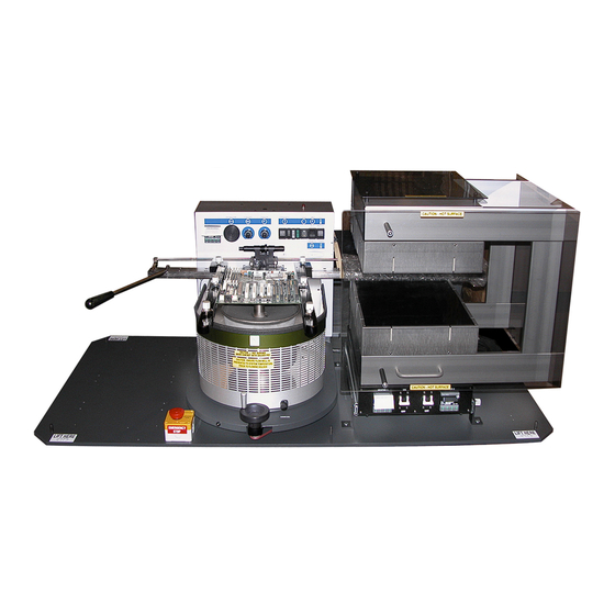
Page 22: Pcbrm System 5.2 - System Overview
PCBRM15 & PCBRM System 5.2 User’s Manual Chapter 2: Requirements/Machine Overview PCBRM System 5.2 – System Overview Cleaning Hood (option) Flow Well Heater Control (option) Compliant Arm Locks X-Rail Handle Flow Well Preheater Z-Axis Positioning X-Axis Stop Knob (preheater) Part No. 4005.00.906... - Page 23 PCBRM15 & PCBRM System 5.2 User’s Manual Chapter 2: Requirements/Machine Overview Bottom Heater Controls Heater Controls Temperature Monitor Box E-Stop Switch Microswitch Z-Axis Positioning Knob Interface Plug Temperature Audible Alarm Microswitch Power Indicator (PCB) Interface Receptical Receptical Type-K Thermocouple Part No. 4005.00.906...
- Page 24 PCBRM15 & PCBRM System 5.2 User’s Manual Chapter 2: Requirements/Machine Overview Preheater Chassis Fuses Y-Axis Preheater Lock Knob Heat Shield (Main) Z-Axis Adjust Wheel Y-Axis Preheater Slides 2-10 Part No. 4005.00.906...
-
Page 25: Pcbrm System 5.2 Pcb Carrier Overview
PCBRM15 & PCBRM System 5.2 User’s Manual Chapter 2: Requirements/Machine Overview PCBRM System 5.2 PCB Carrier Overview Micro switch to activate X-Axis Stop X-Axis Rail Temp. Monitor Box (preheater) X-Axis Stop (preheater) Fume Nozzles In Preheater Y-Axis X-Axis Stop Board Location... - Page 26 PCBRM15 & PCBRM System 5.2 User’s Manual Chapter 2: Requirements/Machine Overview 2-12 Part No. 4005.00.906...
- Page 27 PCBRM15 & PCBRM System 5.2 User’s Manual Chapter 3: Set Up & Installation 3: Set Up & Installation Set Up & Installation ........................3 Leveling Module.............................. 3 PCBRM15 – Carrier Arms Installation....................... 4 PCBRM System 5.2 - Carrier Arms Installation..................7 PCBRM System 5.2 –...
- Page 28 PCBRM15 & PCBRM System 5.2 User’s Manual Chapter 3: Set Up & Installation Part No. 4005.00.906...
-
Page 29: Chapter 3: Set Up & Installation
PCBRM15 & PCBRM System 5.2 User’s Manual Chapter 3: Set Up & Installation Set Up & Installation Leveling Module CAUTION: PERATION OF THIS MODULE INVOLVES PUMPING OF MOLTEN SOLDER LL NORMAL SAFETY PRACTICES SHOULD BE OBSERVED WITH SPECIAL ATTENTION TO THE FOLLOWING... -
Page 30: Pcbrm15 - Carrier Arms Installation
PCBRM15 & PCBRM System 5.2 User’s Manual Chapter 3: Set Up & Installation PCBRM15 – Carrier Arms Installation Install right and left carrier arms to the bearing block • using the M4 screws supplied. When installing the arms, please note that the spring •... - Page 31 PCBRM15 & PCBRM System 5.2 User’s Manual Chapter 3: Set Up & Installation 3. Place the board to be used in the process in to the carrier arms. Align the site to be processed on the board over the flow well and lock in place.
- Page 32 PCBRM15 & PCBRM System 5.2 User’s Manual Chapter 3: Set Up & Installation 6. Loosen the rear two screws of each arm _ turn. 7. Turn the adjustment screw clockwise on both arms equally an 1/8 of a turn at a time until the level is at the desired place.
-
Page 33: Pcbrm System 5.2 - Carrier Arms Installation
PCBRM15 & PCBRM System 5.2 User’s Manual Chapter 3: Set Up & Installation PCBRM System 5.2 - Carrier Arms Installation Loosen lock knob so compliant (carrier) arm lock assembly can straddle the x-axis rail. • Place compliant arm lock assembly in place, as shown. -
Page 34: Pcbrm System 5.2 - X Axis Stops, Set Up, Function
PCBRM15 & PCBRM System 5.2 User’s Manual Chapter 3: Set Up & Installation PCBRM System 5.2 – X Axis Stops, Set Up, Function Locate PCB in carrier arms and lock arms in place using compliant arm lock knobs. • Locate PCB in the y-axis and set stop. -
Page 35: Pcbrm System 5.2 - Z Axis Stop, Set Up, Function
PCBRM15 & PCBRM System 5.2 User’s Manual Chapter 3: Set Up & Installation PCBRM System 5.2 – Z Axis Stop, Set Up, Function The z-axis lock presets a repeatable stop in the Z-Axis for board solder location. • Z-Axis Lock... -
Page 36: Pcbrm System 5.2 - Preheater Safety Stop
PCBRM15 & PCBRM System 5.2 User’s Manual Chapter 3: Set Up & Installation PCBRM System 5.2 - Preheater Safety Stop Safety Stop is removed for shipping. Install once machine is set up. Slide preheater forward and • install screw and washer into hole. Secure with lock washer and nut. Place protective tube over the end of exposed screw. -
Page 37: Optional Fume Extraction Manifold Assembly Installation
Optional Fume Extraction Manifold Assembly Installation • The Optional Fume Extraction Manifold (for PCBRM15 or PCBRM System 5.2) consists of an Overhead Arm (A), two Exhaust Nozzles (B) and 2” Diameter Hoses which can be attached to an in-house or separate filtration system. - Page 38 PCBRM15 & PCBRM System 5.2 User’s Manual Chapter 3: Set Up & Installation • Overhead Arm mounts to bracket (C), which mounts to the left side of the PCBRM (hardware included). 2 ½” hose (¼-20 x 3/8 screws and washers included) 3-12 Part No.
- Page 39 PCBRM15 & PCBRM System 5.2 User’s Manual Chapter 3: Set Up & Installation 2” hose 2 ½” hose 3-13 Part No. 4005.00.906...
- Page 40 PCBRM15 & PCBRM System 5.2 User’s Manual Chapter 3: Set Up & Installation Overarm Connection To Nozzles To Nozzles To Fume System 3-14 Part No. 4005.00.906...
- Page 41 PCBRM15 & PCBRM System 5.2 User’s Manual Chapter 3: Set Up & Installation 2” hose 2 ½” hose Y-Branch 2 ½” hose 2” hose 3-15 Part No. 4005.00.906...
- Page 42 PCBRM15 & PCBRM System 5.2 User’s Manual Chapter 3: Set Up & Installation 3-16 Part No. 4005.00.906...
- Page 43 PCBRM15 & PCBRM System 5.2 User’s Manual Chapter 4: Processes & Applications 4: Processes & Applications Processes & Applications ........................3 Adding Solder ............................3 Flow Well Set-Up ............................4 Cleaning Hood Set Up (option) ........................ 7 Solder Temperature ..........................8 PCB Hole Cleaning Procedure ........................
- Page 44 PCBRM15 & PCBRM System 5.2 User’s Manual Chapter 4: Processes & Applications Part No. 4005.00.906...
-
Page 45: Chapter 4: Processes & Applications
PCBRM15 & PCBRM System 5.2 User’s Manual Chapter 4: Processes & Applications Processes & Applications Adding Solder CAUTION: SE INSULATED GLOVES WHEN WORKING AROUND HEATED AREA E CERTAIN THE WITCH IS IN THE OFF POSITION NEUTRAL POSITION • Remove Pot Cover (A). -
Page 46: Flow Well Set-Up
PCBRM15 & PCBRM System 5.2 User’s Manual Chapter 4: Processes & Applications Flow Well Set-Up Hi/Low Flow Well Heater Adjust Solder Flow Rate Control Flow Well Heater Box Main Power Reset Switch • Push the Main Power and Reset Switches. Process temperature is factory set at 500˚F (adjust as required). - Page 47 PCBRM15 & PCBRM System 5.2 User’s Manual Chapter 4: Processes & Applications • Connect flow well heaters to power, if applicable. Adjust heaters as required. • Allow machine to reach and stabilize temperature—typically 45 minutes. • After flow well has heat soaked for 15 minutes, set Solder Flow Rate Control to zero. Mode Switch and Cycle Machine set to Continuous.
- Page 48 PCBRM15 & PCBRM System 5.2 User’s Manual Chapter 4: Processes & Applications • Using the Z-Axis Height Adjustment Wheel, lower carrier to allow Carrier Arms to touch side of Flow Well. • Adjust Flow Well parallel to carrier arms or use edge of a pcb as a guide to square the flow well as shown in photo.
-
Page 49: Cleaning Hood Set Up (Option)
PCBRM15 & PCBRM System 5.2 User’s Manual Chapter 4: Processes & Applications • Too great of a clearance could prevent the solder from reaching the entire lead pattern. • Cycle machine. With flow rate at zero, switch mode switch to “continuous” mode and slowly adjust Solder Flow Rate Control to produce a level flowing solder wave. -
Page 50: Solder Temperature
PCBRM15 & PCBRM System 5.2 User’s Manual Chapter 4: Processes & Applications APS System (option) • Set Air Regulator to 5-7 psi. Note O NOT SET ABOVE IR PRESSURE MAY DISPERSE MOLTEN SOLDER OLDERING APPLICATIONS PRESSURE MAY BE SET TO ZERO... -
Page 51: Pcb Hole Cleaning Procedure
Where leads are “free”, exert a slight downward force on the component to prevent “floating” of the component when the solder wave contacts the leads. Specific Production Soldering Applications In addition to component removal and replacement, the PCBRM15 is commonly used for Selective Soldering in the production process. Small Sub-Assemblies The PCBRM12 has many advantages compared to hand soldering sub-assemblies. -
Page 52: Temperature Controller (Watlow)
PCBRM15 & PCBRM System 5.2 User’s Manual Chapter 4: Processes & Applications Temperature Controller (Watlow) Programmable Set Points. The Programmable Digital Readout Temperature Controller has two set points that are programmable. “Set point one (SP1)” is the process temperature; “set point two (SP2)” is the standby/interlock temperature. -
Page 53: Temperature Controller (Cal 9900)
PCBRM15 & PCBRM System 5.2 User’s Manual Chapter 4: Processes & Applications Temperature Controller (CAL 9900) Programmable Set Points. The Programmable Digital Readout Temperature Controller has two set points that are programmable. Set point one (SP1) is the process temperature; set point two (SP2) is the standby/interlock temperature. -
Page 54: 4.10 Operator Procedures
PCBRM15 & PCBRM System 5.2 User’s Manual Chapter 4: Processes & Applications 4.10 Operator Procedures 4.10.1 Safety Instructions & Recommendations CAUTION: PERATION OF THIS MODULE INVOLVES PUMPING OF MOLTEN SOLDER LL NORMAL SAFETY PRACTICES MUST BE OBSERVED Personnel • Safety glasses should be worn at all times. -
Page 55: Set-Up And Process A Pcb (Step By Step)
PCBRM15 & PCBRM System 5.2 User’s Manual Chapter 4: Processes & Applications 4.11 Set-Up and Process a PCB (step by step) Set-up: NOTE: E CERTAIN THAT THE PUMP BAFFLE IS INSTALLED INTO THE PUMP DJUST Z AXIS TO ITS HIGHEST POSITION... - Page 56 PCBRM15 & PCBRM System 5.2 User’s Manual Chapter 4: Processes & Applications 5. Move X-Axis carrier to the right. Be certain there is enough travel to locate PCB to the flow well. Adjust arms as required. 5A For System 5.2, be certain there is enough travel to locate the PCB in the preheater. Adjust arms left or right as required.
- Page 57 PCBRM15 & PCBRM System 5.2 User’s Manual Chapter 4: Processes & Applications NOTE: 5.2, YSTEM BE CERTAIN THAT THE PREHEATER IS IN ITS FORWARD POSITION AND LOCKED IN POSITION Lock Knob 6. Move carrier to bring PCB to the flow well location.
- Page 58 PCBRM15 & PCBRM System 5.2 User’s Manual Chapter 4: Processes & Applications 7. Lower Z-Axis to bring the PCB to contact the side of the flow well and square flow well to PCB. Flow Well parallel 4-16 Part No. 4005.00.906...
- Page 59 PCBRM15 & PCBRM System 5.2 User’s Manual Chapter 4: Processes & Applications 8. Raise Z-Axis using Z-Axis height adjustment wheel and adjust PCB to a height of 1/16” above the flow well. 1/16” • For System 5.2, loosen Z-Axis lock knob and then tighten. The Z-Axis height is now set for repetitive applications.
- Page 60 PCBRM15 & PCBRM System 5.2 User’s Manual Chapter 4: Processes & Applications 9. Move PCB in the Y-Axis and align component/lead pattern over the flow well. Use the APS over arm and cleaning hood to locate, if so equipped. Lock the X-Axis carrier lock.
- Page 61 PCBRM15 & PCBRM System 5.2 User’s Manual Chapter 4: Processes & Applications 11. Remove PCB from carrier arms. • For System 5.2, unlock X-Axis carrier lock. Z-Axis X-Axis Adjustment Wheel Carrier Lock 12. Turn on machine and let temperature stabilize. Adjust temperature as required.
- Page 62 PCBRM15 & PCBRM System 5.2 User’s Manual Chapter 4: Processes & Applications 15. Set mode switch to auto (top) position. 16. Place PCB in carrier arms and lock in place with the board lock knobs. • For System 5.2, tape a type K thermocouple to the PCB using Kapton tape. Plug thermocouple into the temperature monitor box as required.
-
Page 63: 4.12 Pcbrm System 5.2 - Soldering Sequence: Using Auto Mode For Soldering
PCBRM15 & PCBRM System 5.2 User’s Manual Chapter 4: Processes & Applications 4.12 PCBRM System 5.2 - Soldering Sequence: Using Auto Mode for Soldering Note OLDER FLOW AND DURATION MUST BE DETERMINED PRIOR TO THESE STEPS Mode Switch X-Axis Lock... -
Page 64: Pcbrm System 5.2 - Soldering Sequence: Using Manual Mode For Soldering
PCBRM15 & PCBRM System 5.2 User’s Manual Chapter 4: Processes & Applications 4.13 PCBRM System 5.2 - Soldering Sequence: Using Manual Mode for Soldering Note OLDER YCLE URATION ONTROL TO MAXIMUM SETTING LOW MUST BE DETERMINED PRIOR TO THESE STEPS... - Page 65 PCBRM15 & PCBRM System 5.2 User’s Manual Chapter 4: Processes & Applications • It may be desired to turn on solder flow while board is in the preheat position to allow flow well to heat soak and dross to be skimmed prior to soldering.
-
Page 66: 4.14 Removal Procedure
PCBRM15 & PCBRM System 5.2 User’s Manual Chapter 4: Processes & Applications 4.14 Removal Procedure 4.14.1 Set Up • Set Ramp Down Flow Rate to 10. • Set Air Regulator to 5-7 psi. • Follow same procedure for automatic soldering procedure. If manual soldering procedure is used, the operator must press the footswitch to stop the solder pumping and activate the hole cleaning system. -
Page 67: 4.15 Component Replacement
PCBRM15 & PCBRM System 5.2 User’s Manual Chapter 4: Processes & Applications Component Removal Process Notes Board must be clamped. If not, when removing the component leads may catch in the barrels and lift the board away from the solder wave during reflow. - Page 68 PCBRM15 & PCBRM System 5.2 User’s Manual Chapter 4: Processes & Applications 4-26 Part No. 4005.00.906...
- Page 69 Pcbrm15 & PCBRM System 5.2 User’s Manual Chapter 5: Maintenance/Parts 5: Maintenance/Parts Maintenance/Parts..........................3 Preventative Maintenance Schedule......................3 Solder Removal ............................... 4 Pump Cleaning..............................4 Pump Disassembly & Cleaning........................5 Pump Leveling..............................8 PCBRM System 5.2 – Specific Parts ......................11 PCBRM15 - Mechanical Breakdown ......................
- Page 70 Pcbrm15 & PCBRM System 5.2 User’s Manual Chapter 5: Maintenance/Parts Part No. 4005.00.906...
-
Page 71: Chapter 5: Maintenance & Parts
Pcbrm15 & PCBRM System 5.2 User’s Manual Chapter 5: Maintenance/Parts Maintenance/Parts Preventative Maintenance Schedule CAUTION: LL SAFETY PRACTICES MUST BE OBSERVED Daily: Clean exterior of machine to rid of solder deposits, flux, and dirt. • Use household cleaners like “409”. -
Page 72: Solder Removal
Pcbrm15 & PCBRM System 5.2 User’s Manual Chapter 5: Maintenance/Parts Solder Removal Use Solder Bailer to transfer solder to a container with a capacity of 150 cubic inches or more. • Most of the solder can be removed with the bailer. Weight of solder is 35 lbs. -
Page 73: Pump Disassembly & Cleaning
Pcbrm15 & PCBRM System 5.2 User’s Manual Chapter 5: Maintenance/Parts Pump Disassembly & Cleaning CAUTION OLDER 7. Remove Pump Baffle (P) using needle nose pliers while pump is in the pot with solder. 8. Remove solder from pot using ladle supplied with unit. - Page 74 Pcbrm15 & PCBRM System 5.2 User’s Manual Chapter 5: Maintenance/Parts This side upper Index Mark See note 1 9000.02.000 See note 1 NOTE 1: Index Mark When cleaning of pump is required, the pump shaft (D) and the pump sleeve insert (R) need to be replaced.
- Page 75 Pcbrm15 & PCBRM System 5.2 User’s Manual Chapter 5: Maintenance/Parts 5.3.1 Replacement of Pump Bearings: Follow all the steps outlined in Pump Disassembly. • After Impeller and Shaft Assembly are removed, the Impeller Pulley, Bearing Spacer, and • Lower Bearing can be removed.
-
Page 76: Pump Leveling
Pcbrm15 & PCBRM System 5.2 User’s Manual Chapter 5: Maintenance/Parts Pump Leveling Carrier Arms Parallel Solder Pump: Tools Needed: 1/16” Allen wrench, − 5/16” Cresent wrench, − Bubble level − Steps: Mount the pump onto the solder pot and snug the mounting screws. DO NOT OVER TIGHTEN. - Page 77 Pcbrm15 & PCBRM System 5.2 User’s Manual Chapter 5: Maintenance/Parts Locate the level in the carrier arm as if it were a PCB. Note the position of the bubble. Place the level • on the pump housing stack the same way. Note the difference between the two bubbles. Determine which two leveling screws will need to be adjusted and by how much.
- Page 78 Pcbrm15 & PCBRM System 5.2 User’s Manual Chapter 5: Maintenance/Parts Install motor belt to pump and motor. Apply downward pressure on motor to achieve belt. Tension • and tighten motor screws. Motor belt Pulley guard Attach pulley guard (2) 1/4 hex head screws.
- Page 79 PCBRM15 & PCBRM System 5.2 User’s Manual Chapter 5: Maintenance/Parts PCBRM System 5.2 – Specific Parts Note PCBRM15 FOR A LIST OF COMMON PARTS Item Part# Description Temperature Controller PH161 Circuit Breaker Proj.DRS.SCS.73 Handle 4005.01.111 Handle Extension ST350 Flow Well Heater Box (option)
-
Page 80: Pcbrm15 - Mechanical Breakdown
Pcbrm15 & PCBRM System 5.2 User’s Manual Chapter 5: Maintenance/Parts PCBRM15 - Mechanical Breakdown Lock Rod 12318 Bracket 12324 Screw 37B - 5/16 x 5/8 - Screw 5A – 6-32 x 1/2 36B - Washer 6B – 6-32 x 3/4 6-32 x 3/16 Idler Gear, SM –... - Page 81 Pcbrm15 & PCBRM System 5.2 User’s Manual Chapter 5: Maintenance/Parts Mechanical Breakdown - Parts List Description Qty. Part Number Solder Pot 12510 Solder Pot Cover 2004.01.108 Pump Assembly, only 2004.01.040 Motor Assembly 12420 Drive Belt - High Temperature 12467 Belt Guard...
-
Page 82: Pcbrm15 -Electrical Compartment
Pcbrm15 & PCBRM System 5.2 User’s Manual Chapter 5: Maintenance/Parts PCBRM15 -Electrical Compartment 1. 9002.05.017 Potentiometer duration, 25K 2. 9002.05.018 Potentiometer flow, 50K 3. 9002.11.051 Temperature controller (Watlow) 4. 12862 Cycle control board 5. 12420 Motor assembly 6. 12865 Pot relay 7. -
Page 83: Pcbrm15 - Fuses
PCBRM15 & PCBRM System 5.2 User’s Manual Chapter 5: Maintenance/Parts PCBRM15 - Fuses 1/4 AMP Slow-Blow 15 AMP 2 AMP 1/2 AMP 3/10 AMP Slow-Blow NOTE: Refer to the schematic # 2004.00.902 5-15 Part No. 4005.00.906... -
Page 84: Tooling
Special Flow Wells and Cleaning Hoods can be manufactured for specific applications where • issues of clearance, adjacent components and mixed technology boards are concerns. Consult Air-Vac for details concerning your specific requirements and the optimum solution. • A detailed dimensioned customer print and sample of the assembly are critical to design. - Page 85 5.9.2 Application Specific Tooling Provides the Most Efficient Process Solution Send your board to Air-Vac for quick assistance to enhance your process and improve productivity. A three-dimensional tooling model can be forwarded to you for viewing. Locating Pins accurately position the lead pattern over the solder wave.
- Page 86 Pcbrm15 & PCBRM System 5.2 User’s Manual Chapter 5: Maintenance/Parts 5.9.3 Standard Flow Wells & Air Cleaning Hoods The flow well must be larger than the component lead pattern to insure that all leads are within the solder wave. Generally an edge distance of 1/16” is added around the lead pattern and on long connectors where heat dissipates at the end of the well, an edge distance of 3/16”...
- Page 87 Pcbrm15 & PCBRM System 5.2 User’s Manual Chapter 6: Troubleshooting 6: Troubleshooting Troubleshooting ..........................3 Air-Vac Technical Service ........................3 Common Problems/Solutions ........................3 Temperature Controller Installation (CAL 9900 only) ................. 5 Part No. 4005.00.906...
- Page 88 Pcbrm15 & PCBRM System 5.2 User’s Manual Chapter 6: Troubleshooting Part No. 4005.00.906...
-
Page 89: Chapter 6: Troubleshooting
Chapter 6: Troubleshooting Troubleshooting Air-Vac Technical Service Air-Vac is always willing to assist our customers with any technical or operating questions. If you have any questions on machine parameters, correct nozzle requirements, options, procedures or maintenance, please do not hesitate to call. - Page 90 Pcbrm15 & PCBRM System 5.2 User’s Manual Chapter 6: Troubleshooting 6.1.3 Poor Solder Results 1. Un-level pump (see leveling procedure). 2. Un-level machine (see leveling procedure). 3. Z-Axis height not set correctly. 4. Baffle not being used. 5. Flow duration not set correctly.
- Page 91 Pcbrm15 & PCBRM System 5.2 User’s Manual Chapter 6: Troubleshooting Temperature Controller Installation (CAL 9900 only) 1. Remove the socket by pressing in the lock buttons. 2. Slide the controller into the cut-out. 3. Fit the mounting clip by pressing it firmly against the panel, jacking screws optional.
- Page 92 Pcbrm15 & PCBRM System 5.2 User’s Manual Chapter 6: Troubleshooting Part No. 4005.00.906...
- Page 93 Pcbrm15 & PCBRM System 5.2 User’s Manual Chapter 7: Schematics 7: Schematics Part No. 4005.00.906...
- Page 94 Pcbrm15 & PCBRM System 5.2 User’s Manual Chapter 7: Schematics Part No. 4005.00.906...
Need help?
Do you have a question about the PCBRM15 and is the answer not in the manual?
Questions and answers