joke ENESKAmicro 600 Operating Instructions Manual
Hide thumbs
Also See for ENESKAmicro 600:
- Operating instructions manual (35 pages) ,
- Brief instructions (12 pages)
Table of Contents
Advertisement
Quick Links
Advertisement
Table of Contents

Related Manuals for joke ENESKAmicro 600


Summary of Contents for joke ENESKAmicro 600
- Page 1 Operating instructions ENESKAmicro 600 ENESKAmicro 450 ENESKAmicro 600 PLC...
-
Page 2: Table Of Contents
Table of contents 1 Notes on this manual . . . . . . . . . . . . . . . . . . . . . . . . . . . . . . . . . . . . . . . . . . . . . . . . . 4 2 Product overview . - Page 3 13 .4 Parametrising the PLC . . . . . . . . . . . . . . . . . . . . . . . . . . . . . . . . . . . . . . . . . . . . . . . . . . . . . . . . 35 13.4.1 Activate “Run/stop”...
-
Page 4: Notes On This Manual
For technical problems or other questions please contact our service department. ► Product overview Fig. 1 Collet Motor cable Handpiece ENESKAmicro control unit Motor You will find a comprehensive system overview in the joke surface treatment catalogue, in the “Drive systems and handpieces” section. -
Page 5: Technical Data
0 °C to +40 °C Ambient conditions 10 % to 85 % humidity USB charging port USB Type-A, 5 V to 1.8 A ENESKAmicro 600 and 600 PLC control unit Connections A and B for brushless DC motors Motor connections Connection C for carbon brush motors Supply voltage... - Page 6 Approved motors Max . speed Handpiece Motor cable (rpm) – motor connection ENESKAmicro motor SE3 50 000 (–) ENESKAmicro S ENESKAmicro motor SE4 50 000 ENESKAmicro S ENESKAmicro COMPACT SE 50 000 COMPACT ENESKAmicro HT ENESKAmicro COMPACT HT60 60 000 COMPACT ENESKAmicro HT ENESKAmicro COMPACT HT60 SMALL...
- Page 7 Approved Max . speed Connection extenders (rpm) JCN 01 35 000 (–) JEEA 40 000 Rapid change Approved handpieces with a (+) connection Max . speed (rpm) JBS 400 belt grinder 15 000 DIPROFIL Di-Pro FXM-N, Mark II hand-held filing machine 7 000 (strokes) DIPROFIL FPM/ERJ, Mark II hand-held filing machine 7 000 (strokes)
-
Page 8: Nameplate
Approved handpieces with rapid change connection Max . speed (rpm) 50 000 (continuous operation: 40 JIR 40R quick-release handpiece 000) 50 000 (continuous operation: 40 JIH 40R one-handed handpiece 000) JBMLH 40R handpiece 40 000 JBMXLH 40R handpiece 40 000 JEHG 20R handpiece 20 000 JERA 90 20R angled handpiece... -
Page 9: Safety
When working with the ENESKAmicro system, always wear safety glasses, safety gloves and ► hearing protection. Ensure sufficient extraction of any dust particles that may arise. ► Eliminate faults immediately according to these instructions or have them eliminated by joke ► Service. Use only original parts from the joke. ►... -
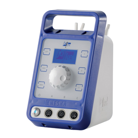
Page 10: Controls And Indicators
Controls and indicators 18.000 _____ > – – – L20k Fig. 3 Power switch Connection B (BLDC - brushless DC motor) Connection C (DC carbon brush motor; if [MEM] button available) [FOOT] button USB charging socket (type A) Foot pedal or PLC connection [LEFT] button (PLC depending on version) Display... -
Page 11: Commissioning Of The Controller
Commissioning of the controller Note The operation described in the following chapters is based on software versions V.04x and V.05x. For units with older versions, the information is not valid. 6 .1 Replacing the fuse (if necessary) The control unit is factory set to 230 V and equipped with two 2 A micro-fuses. One of these two is intended to be a spare. -
Page 12: Setting Up The Control Unit
230 V 115 V 180° Fig. 5 6 .2 Setting up the control unit Attention! Humidity entering the unit or its accessories may cause a short circuit. Do not use the unit or its accessories in conditions that may cause condensation to occur in or ►... -
Page 13: Connecting The Mains Cable And Switching On The Unit
Use only the original mains cable or approved equivalent power cord. ► Fig. 6 > Vx.xx. 3.000 _____ > – – – – Fig. 7 Immediately after switching on, the unit displays the joke logo and firmware version. 13 13... -
Page 14: Connecting The Motor Cable To The Unit
6 .4 Connecting the motor cable to the unit Attention! Always insert the cable carefully into the socket on the control unit and make sure that the ► contacts and threads are not damaged. • Connection A: Brushless DC motor • Connection B: Brushless DC motor •... -
Page 15: Connecting A Handpiece
6 .5 Connecting a handpiece Attention! Carefully push the motor and the handpiece together and make sure that the contacts, the ► motor shaft, the handpiece coupling and the threads are not damaged. Use only the supplied tool. ► Fig. 10 Connect the motor and handpiece (example illustration) If there is resistance before the thread is completely screwed in, or if the connection is not ►... -
Page 16: Setting The Language (If Necessary)
6 .6 Setting the language (if necessary) Action Display = ESC = Main menu = ----------------------------------- - Language - Unit info - Options - Interfaces Open main menu = ESC = Main menu = ----------------------------------- - Language - Unit info - Options - Interfaces Select “Sprache/Language”... -
Page 17: Commissioning Of The Motor On The Controller
Commissioning of the motor on the controller 7 .1 Switching the unit on and off Fig. 12 7 .2 Selecting a motor Several motors can be connected to the control unit at the same time, but only one motor can be used at a time. -
Page 18: Selecting The Direction Of Rotation
7 .3 Selecting the direction of rotation Anti-clockwise rotation can only be selected if the handpiece is approved for two directions of rotation. Option A: 2.000 _____ LEFT LEFT > – – – – FOOT LEFT Fig. 13 Option B (only if this function has been enabled via the control unit see chapter 11 .2 on page 25): >... -
Page 19: Setting The Speed
7 .4 Setting the speed Warning! To prevent injury and damage to components caused by high speeds: Never exceed the maxi- ► mum permitted speed of the connected components and accessories. Attention! To avoid damage to the handpiece: Reduce the speed if the tool protrusion is more than 13 mm. ►... -
Page 20: Starting The Motor
7 .5 Starting the motor ____ Fig. 16 7 .6 Stopping the motor _____ Fig. 17 20 20... -
Page 21: Using The Memory Function (Mem)
7 .7 Using the memory function (MEM) The memory function makes it possible to store one speed, one direction of rotation (anti-clock- wise or clockwise) and the activated foot operation for each of the three connections (A, B or C) so that the settings are retained even if the control unit is switched off and then on again. -
Page 22: Main Menu Overview
On/Off Activates/deactivates the “Diagnostics Page 28 screen screen” option Ext. input Pedal 1 For use of joke foot pedal, item no. Page 29 0011002 Pedal 2 For use with standardised foot pedals, e.g. 0 011 003 PLC control For use with units with the “PLC Control”... -
Page 23: Opening The Main Menu And Navigating Within Menus
Opening the main menu and navigating within menus Open the main menu. To do this, press the rotary control rotary encoder twice. ► Action Display = ESC = Main menu = ----------------------------------- - Language - Unit info - Options - Interfaces Open main menu Select a submenu or Display the selected menu... -
Page 24: Displaying Information About The Unit
Displaying information about the unit Action Display = ESC = U-INFO ----------------------------------- - Operating times - Events - Version [C]=ESC Select the type of information = ESC = INFO-MOT = ----------------------------------- Order of displays: [Mem] A X.XXX/R [Mem] B XX.XXX/L Channel memory allocation [Mem] C XX % /L... -
Page 25: Unit Functions In The "Options" Menu
Unit functions in the “Options” menu 11 .1 Setting the “Timer” option The “Timer” option allows you to set a timer. As soon as a motor runs without a load, a timer starts and switches the motor off once the set time has elapsed. The factory setting is one minute. -
Page 26: Adjusting The Speed Limiter In Anti-Clockwise Rotation
11 .3 Adjusting the speed limiter in anti-clockwise rotation To prevent incorrect settings for working with certain tools, the speed can be additionally limited in anti-clockwise rotation. Action Display = ESC = OPTIONS ----------------------------------- ____________ = ___ ____________ = ___ Speed in rpm Limit Left rpm = XX... -
Page 27: Activating The "Diagnostics Screen" Option
11 .5 Activating the “Diagnostics screen” option To access the diagnostics screen, you must first activate the “Diagnostics screen” function in the “Options” menu. As long as the “Diagnostics screen” option is activated, you can switch directly between the main display and the diagnostic screen. Note The “Diagnostics screen”... -
Page 28: Overview Of "Diagnostics Screen
11 .5 .1 Overview of “Diagnostics Screen” The diagnostics screen displays the following operating data. 18.000 _____ Error : – – – M. Type: ________ 1/min : ________ _______ I(act.) : ____ A > Temp. : Z ____ B ____ UZKW : ____ V –... -
Page 29: External Control Input" Option (Ext . Input) Assign
This option sets the foot controller input of the controller to a standardised input signal from 0 V to 5 V. Select this setting to use standardised foot pedals. If you select this option, you will not be able to use the joke foot pedal with 4-pin diode plug (item no. 0011002). Alternative item no.: 0 011 003. -
Page 30: Using The Foot Pedal On The External Input
Using the foot pedal on the external input A foot pedal can be used to control the speed of the tool using your foot during operation. Vari- able speeds between 0 and the set speed can be used this way. 18.000 _____ FOOT –... -
Page 31: Fixing The Speed Of The Foot Pedal (Fix-It)
12 .1 Fixing the speed of the foot pedal (FIX-it) If you use the FIX-it function, you can fix the speed of the motor while working with the foot pedal. Once the FIX-it function is activated, you can release the foot pedal and the motor con- tinues to rotate at the fixed speed. - Page 32 Use the FIX-it function via the handpiece Press and hold the foot pedal to control the motor. ► Activate the FIX-it function. To do this, press the ON/OFF button on the handpiece. ► Take your foot off the foot pedal. ►...
-
Page 33: Plc Operating Mode For External Motor Control
In PLC mode, the manual operating functions via the handpiece as well as the setting options for speed and direction of rotation via the control unit are deactivated. Note Operation with an external PLC controller is only possible with the ENESKAmicro 600 PLC control unit. 13 .1 Keys in PLC mode As long as the unit is automatically controlled via PLC, the unit’s buttons light up to signal the... -
Page 34: Main Display In Plc Mode
13 .2 Main display in PLC mode As long as the unit is automatically controlled via PLC, the main display shows the following information: 18.000 1/min t=off > PLC A B C Sp1 Fig. 25 Indicates that the timer function is deactivated Display of timer function The timer function cannot be used in PLC mode. -
Page 35: Parametrising The Plc
With the “Run/stop” option for contact-controlled control, you can specify 2 set speeds for each motor channel. You must specify these set speeds individually for each motor channel (A, B, C). The minimum values and maximum values are limited to the permissible value range of the connected joke motor. Connect the desired motors. ►... -
Page 36: Connecting The Plc
13 .5 Connecting the PLC You can control the unit via 4 inputs and 1 output. The connection to a superordinate controller must be carried out by an electrician. Fig. 26 For the correct connection of the inputs, observe the following circuit diagram (Fig. 27). ►... - Page 37 Fig. 27 37 37...
-
Page 38: 14 "Interface" Menu Access Options
“Interface” menu access options 14 .1 Firmware update The firmware of your ENESKAmicro can be updated to the latest version by joke Service. Firm- ware updates can support new joke motors to meet customer requirements, for example. 14 .2 PLC control This menu is only available if your unit has the optional extension “PLC”. -
Page 39: Fitting The Tool And Collet
Fitting the tool and collet Warning! The collet and tool can become hot during operation. You may burn yourself on hot components. Let the collet and tool cool down before you work on them. ► Warning! To avoid injury from unintentional rotation of the tool, switch off the control unit before con- ►... -
Page 40: Ht60-D6 (Cnc)
15 .1 .2 HT60-D6 (CNC) Fig. 29 15 .1 .3 JEHG 400, JHG 210 Fig. 30 40 40... -
Page 41: Jehr 500, Jir 310, Jem 50C (Cnc), Jir 40R
15 .1 .4 JEHR 500, JIR 310, JEM 50C (CNC), JIR 40R, CLICK CLICK Fig. 31 15 .1 .5 JERA 270 Fig. 32 41 41... -
Page 42: Jbmxlh 40R, Jbmh 300 N, Jbmlh 40R, Jehg 20R
15 .1 .6 JBMXLH 40R, JBMH 300 N, JBMLH 40R, JEHG 20R Fig. 33 15 .1 .7 JERA 270 S Fig. 34 42 42... -
Page 43: Jih 300, Jih 40R
15 .1 .8 JIH 300, JIH 40R 90° 90° Fig. 35 15 .1 .9 JKC 345, JIC 390, JEKC 300, WE4-45, WE4-90, JERA 90 20R, JEAH 60 20R Fig. 36 43 43... -
Page 44: Jmfc 300 S, Jmfc 300 M
15 .1 .10 JMFC 300 S, JMFC 300 M Fig. 37 44 44... -
Page 45: Changing The Collet
15 .2 Changing the collet Switch off the motor and the control unit. ► Disconnect the motor cable from the motor connector on the control side. ► To change the collet, observes to the following figures. ► 15 .2 .1 COMPACT SE CLICK Fig. -
Page 46: Ht60, Ht60-Xl
15 .2 .2 HT60, HT60-XL Fig. 39 15 .2 .3 HT60-D6 (CNC) Fig. 40 46 46... -
Page 47: Ht60 Small
15 .2 .4 HT60 SMALL CLICK Fig. 41 47 47... -
Page 48: Jehg 400, Jhg 210
15 .2 .5 JEHG 400, JHG 210 Fig. 42 15 .2 .6 JEHR 500, JIR 310 Fig. 43 48 48... -
Page 49: Jbmxlh 40R, Jem 50C (Cnc), Jir 40R, Jbmh 300 N, Jbmlh 40R, Jehg 20R
15 .2 .7 JBMXLH 40R, JEM 50C (CNC), JIR 40R, JBMH 300 N, JBMLH 40R, JEHG 20R Fig. 44 15 .2 .8 JERA 270 Fig. 45 49 49... -
Page 50: Jera 270 S
15 .2 .9 JERA 270 S Fig. 46 15 .2 .10 JIH 300, JIH 40R 90° 90° Fig. 47 50 50... -
Page 51: Jkc 345, Jic 390, Jekc 300, We4-45, We4-90, Jera 90 20R, Jeah 60 20R
15 .2 .11 JKC 345, JIC 390, JEKC 300, WE4-45, WE4-90, JERA 90 20R, JEAH 60 20R Fig. 48 15 .2 .12 JMFC 300 S, JMFC 300 M Fig. 49 51 51... -
Page 52: Maintenance, Care And Disposal
Servicing and maintenance instructions After approx. 4 200 operating hours, the message “S E R V I C E” appears in the display after each unit start. The “S E R V I C E” message is repeated until it is reset by joke Service. Contact joke Service and make an appointment if necessary. -
Page 53: Troubleshooting
► Replace the defective micro-fuse. faulty. • Control unit, cables, connections, ► Send the unit and accessories to joke contacts, mains switch or sockets are Service for inspection or repair. faulty. The motor will • The motor or handpiece have been ►... - Page 54 Unit error ► Switch the unit off and then on again. ► Replace the motor. Send the unit and accessories to joke ► Service for inspection or repair. Main board overtemperature: ► Let the unit cool down when it is switched off.
- Page 55 55 55...
-
Page 56: Declaration Of Conformity
• DIN EN 61010-1 VDE 0411-1 (2011-07): Safety requirements for electrical equipment for meas- urement, control and laboratory use – Part 1: General requirements The authorised representative for the document is: Kerstin Otto joke Technology GmbH, Asselborner Weg 14-16, 51429 Bergisch Gladbach, Germany Bergisch Gladbach, 31 January 2023 Udo Fielenbach (Managing Director) ___________________... -
Page 57: Declaration Of Conformity
• Directive:RoHS Directive :2011/65/EU using the following harmonised standards EN50581:2012 The authorised representative for the document is: Kerstin Otto joke Technology GmbH, Asselborner Weg 14-16, 51429 Bergisch Gladbach, Germany Bergisch Gladbach, 31 January 2023 Udo Fielenbach (Managing Director) ___________________ 57 57... - Page 58 Mail info@joke.de Web www.joke-technology.com Order number for operating manual: BA2241GB © Copyright joke Technology GmbH • May 2023 • Subject to changes due to technical progress, errors and misprints • Reproduction, in whole or in part, only with prior written permission.
Need help?
Do you have a question about the ENESKAmicro 600 and is the answer not in the manual?
Questions and answers