Advertisement
PROJECT NAME
MINIMA
BASED ON
Mu-tron® Micro V
EFFECT TYPE
Envelope filter / auto-wah
PROJECT SUMMARY
A simplified version of the more famous Mu-tron III envelope filter, originally designed as a lower-cost
alternative.
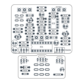
Actual size is 2.3" x 1.86" (main board) and 1.78" x 0.86" (bypass board).
MINIMA RESONANT FILTER
BUILD DIFFICULTY
Easy
DOCUMENT VERSION
1.0.0 (2023-09-08)
1
Advertisement
Table of Contents

Related Manuals for aion Minima


Summary of Contents for aion Minima
- Page 1 Envelope filter / auto-wah 1.0.0 (2023-09-08) PROJECT SUMMARY A simplified version of the more famous Mu-tron III envelope filter, originally designed as a lower-cost alternative. Actual size is 2.3” x 1.86” (main board) and 1.78” x 0.86” (bypass board). MINIMA RESONANT FILTER...
-
Page 2: Table Of Contents
ARP. The Minima is a slightly expanded version of the original Micro V circuit. The two fixed resistors that set the attack and release of the envelope detector have been made variable, and we’ve added a third in- between position to the “Hi/Lo”... -
Page 3: Parts List
Film capacitor, 7.2 x 2.5mm Film capacitor, 7.2 x 2.5mm Film capacitor, 7.2 x 2.5mm Film capacitor, 7.2 x 2.5mm Film capacitor, 7.2 x 2.5mm Film capacitor, 7.2 x 2.5mm 10uF Electrolytic capacitor, 5mm 4.7uF Electrolytic capacitor, 4mm MINIMA RESONANT FILTER... - Page 4 DC jack, 2.1mm panel mount Mouser 163-4302-E or equivalent. BATT Battery snap 9V battery snap Optional. Use the soft plastic type—the hard-shell type will not fit. 3PDT Stomp switch, 3PDT 125B Enclosure, die-cast aluminum Can also use a Hammond 1590N1. MINIMA RESONANT FILTER...
-
Page 5: Build Notes
The frequency switch on the original Micro V is a 2-position switch with “Lo” and “Hi” modes. The Minima adds a 3rd mode in between the other two with the use of a DPDT on-off-on switch. “Lo” is the bottom position, “Hi” is in the middle, and “Mid” is the top position. (Note that the original Micro V factory schematic reverses the “hi”... -
Page 6: Schematic
SCHEMATIC IC1_BUF1 LM13700N 2N5088 1N5817 100uF 100n IC1A LM13700N IC1_BUF2 100uF LM13700N 100pF IC2B 2N5088 100k LM1458P IC1B LM13700N 4.7uF RANGE 1N914 ATTACK 4.7uF 2N5087 220R 1N914 IC2A LM1458P MINIMA RESONANT FILTER... -
Page 7: Drill Template
ATTACK DECAY x: -0.65, y: +1.71 x: 0.65, y: +1.71 ø9/32” ø9/32” RANGE FREQUENCY x: 0, y: +0.66 x: +0.85, y: +0.66 ø9/32” ø1/4” CENTER (0,0) FOOTSWITCH x: -0.775, y: -1.20 x: 0, y: -1.20 ø5/16” ø15/32” MINIMA RESONANT FILTER... -
Page 8: Enclosure Layout
ENCLOSURE LAYOUT Enclosure is shown without jacks. See next page for jack layout and wiring. 125B MINIMA RESONANT FILTER... -
Page 9: Wiring Diagram
GND +V +V JACK GND JACK GND GND PCB 125B Shown with optional 9V battery. If battery is omitted, both jacks can be mono rather than one being stereo. Leave the far-right lug of the DC jack unconnected. MINIMA RESONANT FILTER... -
Page 10: Document Revisions
(In other words: you don’t have to go out of your way to advertise the fact that you use these PCBs, but please don’t go out of your way to hide it. The guitar effects industry needs more transparency, not less!) DOCUMENT REVISIONS 1.0.0 (2023-09-08) Initial release. MINIMA RESONANT FILTER...
Need help?
Do you have a question about the Minima and is the answer not in the manual?
Questions and answers