Table of Contents
Advertisement
Quick Links
Advertisement
Table of Contents

Subscribe to Our Youtube Channel
Related Manuals for TEEHO RZ09


Summary of Contents for TEEHO RZ09
- Page 1 RZ09 Smart Lock User Guide / Installation Instruction Thank you for purchasing our products. Please review this manual thoroughly before operating your device. All pictures in this manual are for illustration purpose only. Actual product may vary due to product upgrade.
- Page 2 User Guide Installation Instruction At a Glance STEP 1: Prepare the door and check dimensions How to Lock / Unlock STEP 2: Install the latch and strike Definitions STEP 3: Install exterior assembly P 10 STEP 4: Install interior assembly P 12 Factory default settings P 13...
-
Page 3: Interior Assembly
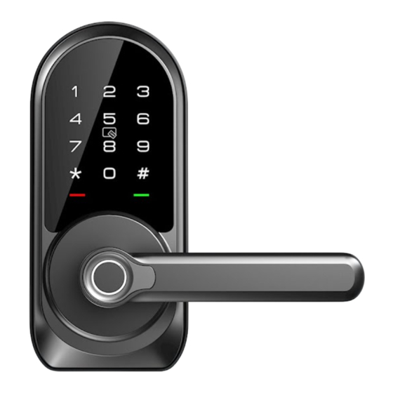
USER GUIDE At a Glance Exterior Assembly Interior Assembly Battery Cover Keypad IC card Touch Area Reset Button Indicator Lights Passage Switch Fingerprint Keyhole... - Page 4 How to Lock / Unlock UNLOCK the door from inside UNLOCK the door from outside Card or Right Hand Left Hand Backup Key LOCK the door from outside LOCK the door from inside Auto Lock Mode Tap and hold Lock icon in App to lock.
- Page 5 Definitions • Master Code • Passage Mode The default master code is 123456. Move the Passage Switch to enable and disable the Passage Mode. Before pairing your lock in DDLock App, please do not change the Enable Passage Mode, the lock will stay Unlocked until it’s locked default master code.
-
Page 6: Installation Instruction
INSTALLATION INSTRUCTION Interior Battery Assembly (G) Cover (H) Mounting Exterior Assembly plate (E) Screw (F) Interior Assembly Screws (L) Exterior Assembly Latch (C) Mounting plate Screws (K) Strike (D) Latch Screws Strike Screws Backup key (A) -
Page 7: Parts List
Parts List Exterior Assembly x1 Strike x1 Backup Key x2 Latch x1 Mounting Plate x1 Exterior Assembly Interior Assembly x1 Strike Screws x2 Screw (Optional) Latch Screws x2 Battery Cover x1 Interior Assembly Drive-In Collar (Optional) IC Card x2 Mounting Plate Screws x2 Screws x3 Reset Tool x1 If any parts are missing or damaged, please contact Customer Support. - Page 8 STEP Prepare the door and check dimensions 2-3/8" or 2-3/4" (60 or 70mm) Measure to Measure to confirm confirm that the that the backset is hole in the door is either 2-3/8" or 2-1/8" 2-1/8" (54mm) 2-3/4" (60 or 70mm) Measure to confirm 1"...
- Page 9 STEP Install the latch and strike If the backset of your door is Latch backset adjustment 2-3/8"(60mm), no need to adjust the latch. 2-3/8" (60mm) If the backset of your door is 2-3/4"(70mm), please adjust the latch. Backset is the distance from the door edge to the center of the hole in the door.
- Page 10 Install strike on the door frame. IMPORTANT: Make sure the hole in door frame is Strike Screws (I) drilled a minimum of 1" (25mm) deep. Notes: The handle direction can be changed for compatible with both right handed and left handed doors. Change Handle Direction (Optional) Change the Handle direction of exterior assembly.
-
Page 11: Install Exterior Assembly
STEP Install exterior assembly Exterior Assembly Keep parallel to Screw (F) (Optional) door edge. Mounting plate Screws(K) Route the cable below the latch, and insert the Secure the mounting plate with the supplied screws. torque blade through the slot in the latch. Do not overtighten screws. -
Page 12: Install Interior Assembly
STEP Install interior assembly Push the battery cover out in the direction as illustrated. IMPORTANT: Do not load batteries until lock is completely installed. Insert the cable connector to the socket. Push the connector in firmly until it is completely attached. - Page 13 STEP Install interior assembly Attach Interior Assembly to Mounting Plate and tighten 3 Screws. Interior Assembly Screws (L) Insert 4 AA Alkaline batteries and put on the battery cover.
-
Page 14: Factory Default Settings
Factory Default Settings How to Reset? Reset button Press and hold the Reset button on the interior assembly for 5 seconds by using the Reset tool, until you hear a short beep and Green light flashes once. If the lock is paired successfully, please locate IMPORTANT: the lock, go to setting in DDLock App, turn on the Reset Button before resetting. -
Page 15: Programming Guide
Programming Guide 123456 The default master code is . Before programming in the lock, it's required that you change IMPORTANT: the default master code to a new master code of your own. If you have changed the default master code by following the Programming Guide, you must reset the lock before pairing this lock to DDlock App. - Page 16 Programming Guide Unwanted user New User Code + Same New User Code + Change Code + User Code 2 Long beeps+2 Green 3 beeps 3 beeps 3 beeps light flash Master Code + Delete All User Code 2 Long beeps+2 Green 3 beeps light flash Scan 4 Times Fingerprint (Each time...
-
Page 17: Troubleshooting
Troubleshooting Why the lock won’t accept any inputs after I entered a code or fingerprint incorrectly for so many times? The lock will shut down for 2 minutes after 5 unsuccessful attempts at entering an invalid code or fingerprint. You can unlock the lock once in the App or wait 2 minutes to continue. How do I lock manually from outside? Press and hold # to lock the lock from outside. -
Page 18: Fcc Statement
FCC Statement ISED Statement This equipment has been tested and found to comply with the limits for a English: This device contains licence-exempt transmitter(s)/receiver(s) that comply with Innovation, Science and Economic Development Class B digital device, pursuant to part 15 of the FCC Rules. These limits Canada’s licence-exempt RSS(s). -
Page 19: Information & Safety Warnings
Information & Safety Warnings • Protect your User Codes and Master Code. • Care should be taken to ensure a long-lasting finish. When cleaning is required use a soft, damp cloth. Using lacquer thinner, caustic soaps, • Restrict access to your lock’s interior assembly and routinely check your abrasive cleaners or polishes could damage the coating and result in settings to ensure they have not been altered without your knowledge.
Need help?
Do you have a question about the RZ09 and is the answer not in the manual?
Questions and answers