Advertisement
INSTRUCTION MANUAL
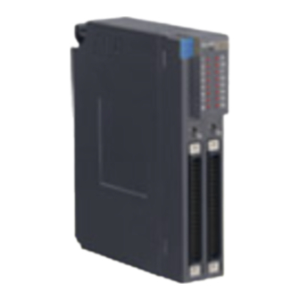
DISCRETE OUTPUT MODULE
(Do 64 points; open collector)
BEFORE USE ....
Thank you for choosing us. Before use, please check con-
tents of the package you received as outlined below.
If you have any problems or questions with the product,
please contact our sales office or representatives.
■ PACKAGE INCLUDES:
Discrete output module.......................................................(1)
■ MODEL NO.
Confirm Model No. marking on the product to be exactly
what you ordered.
■ INSTRUCTION MANUAL
This manual describes necessary points of caution when
you use this product, including installation, connection and
basic maintenance procedures.
MG CO., LTD. www.mgco.jp
5-2-55 Minamitsumori, Nishinari-ku, Osaka 557-0063 JAPAN
MODEL
POINTS OF CAUTION
■ CONFORMITY WITH EU DIRECTIVES
• The equipment must be mounted inside the instrument
panel of a metal enclosure.
• The actual installation environments such as panel con-
figurations, connected devices, connected wires, may af-
fect the protection level of this unit when it is integrated
in a panel system. The user may have to review the CE
requirements in regard to the whole system and employ
additional protective measures to ensure the CE conform-
ity.
■ HOT SWAPPABLE MODULES
• Replacing the module does not affect other modules on
the same base. Thus, the module can be replaced while
the power is ON. However, replacing multiple modules
at once may greatly change live voltage levels. We highly
recommend to replace them one by one.
■ GENERAL PRECAUTIONS
• DO NOT set the switches on the module while the power
is supplied. The switches are used only for maintenance
without the power.
■ ENVIRONMENT
• Indoor use.
• When heavy dust or metal particles are present in the
air, install the unit inside proper housing with sufficient
ventilation.
• Do not install the unit where it is subjected to continuous
vibration. Do not subject the unit to physical impact.
• Environmental temperature must be within -10 to +55°C
(14 to 131°F) with relative humidity within 30 to 90% RH
in order to ensure adequate life span and operation.
■ WIRING
• Do not install cables close to noise sources (relay drive
cable, high frequency line, etc.).
• Do not bind these cables together with those in which
noises are present. Do not install them in the same duct.
INSTALLATION
Use the Installation Base (model: R3-BSx).
R3-DC64A
EM-8413 Rev.5 P. 1 / 4
Advertisement
Table of Contents

Related Manuals for M-system R3-DC64A


Summary of Contents for M-system R3-DC64A
- Page 1 INSTRUCTION MANUAL DISCRETE OUTPUT MODULE R3-DC64A MODEL (Do 64 points; open collector) BEFORE USE ..POINTS OF CAUTION Thank you for choosing us. Before use, please check con- ■ CONFORMITY WITH EU DIRECTIVES tents of the package you received as outlined below.
- Page 2 R3-DC64A COMPONENT IDENTIFICATION FRONT VIEW SIDE VIEW RUN LED Output Status Indicator LEDs ERR LED Group Selector* • Connector Pin Assignment Output Connector Output Hold *Status Indicator LEDs show output status by 16-point group specified with Group Selector. Group Selector position 1 means CN1, while 2 means CN2.
- Page 3 R3-DC64A ■ CONNECTION DIAGRAM Do 11 Do 51 INTERNAL BUS A Do 12 Do 52 * INTERNAL BUS B Do 13 Do 53 Do 14 Do 54 INTERNAL POWER Do 15 Do 55 Do 16 Do 56 Do 17 Do 57...
- Page 4 R3-DC64A OUTPUT CONNECTOR (40 pins) ■ CN1 ■ CN2 PIN NO. ASSIGNMENT PIN NO. ASSIGNMENT PIN NO. ASSIGNMENT PIN NO. ASSIGNMENT Do 11 Do 31 Do 51 Do 71 Do 12 Do 32 Do 52 Do 72 Do 13 Do 33...
Need help?
Do you have a question about the R3-DC64A and is the answer not in the manual?
Questions and answers