
Related Manuals for ePropulsion MPPT096020G


Summary of Contents for ePropulsion MPPT096020G
- Page 1 G Battery Solar Charge MPPT User Manual controller 2 kW Model: MPPT096020G 2023.07 Version Copyright © 2023 ePropulsion. All Rights Reserved...
-
Page 3: Acknowledgement
Before use of the product, please read this user manual thoroughly to understand the correct and safe operations. By using this product, you hereby agree that you have fully read and understood all contents of this manual. ePropulsion accepts no liability for any damage or injury caused by operations that contradict this manual. - Page 4 13mm Caution: When installing, operating, maintaining or serving ePropulsion products, there are many safety 86mm 90mm risks in the process. You need to be alert, perform relevant operations reasonably, and pay attention to safety. Electric shock hazard: The areas or equipment may be at risk of electric shock. The equipment uses 102.4V DC power.
-
Page 5: Table Of Contents
Table of Contents Acknowledgement ....................1 Using This Manual ....................1 Symbols ......................... 1 1 Product Overview ....................4 1.1 Product list ......................4 1.2 Parts and Diagram ....................6 1.3 Specifications ......................7 1.4 Dimensions ......................8 1.5 Reference Table for Number of PV Modules in Series ........8 1.6 Port Pin Definitions ....................9 1.6.1 6P Connector Definitions ................9 1.6.2 Solar Panel Connector Definitions ............ -
Page 6: Product Overview
1 Product Overview This product can real-time detect the power generation of the solar panel and track the maxi- mum voltage-current value to achieve the maximum power output for charging the battery. It is designed for off-grid photovoltaic systems and serves as the core control component that coor- dinates the operation of the solar panel, battery, and devices in off-grid photovoltaic systems. - Page 7 Items Qty. Figure Function M4 Self-tapping Used to fix mounting M5x20 Screws bracket on the boat wall Hexagonal Column Used to fix mounting Head Triple M4X22 bracket on the boat wall Combination Bolts Hexagonal Nuts Used to fix bolts 滚滚长江东逝水 485essA box Connect to 6P Connector CAN cable...
-
Page 8: Parts And Diagram
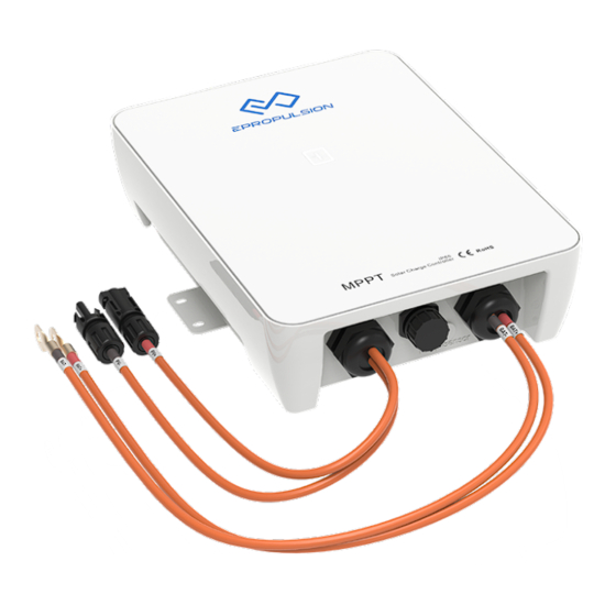
1.2 Parts and Diagram Figure 1-1 Name Name Indicator Output Power Cable RJ45 Serial Communication Mounting Holes for Installation Interface Accessories Red(PV+) Blue(PV-) Temperature Sensor Line Interface Heat Sink Earth Connection Point Input Power Cable... -
Page 9: Specifications
1.3 Specifications Model MPPT096020G Electrical Parameters Voltage Platform 96Vdc Output Voltage Range 72Vdc - 120Vdc Voltage Deviation < +/- 0.2 V Maximum Charging Current 20 A Photovoltaic voltage input range 140Vdc-250Vdc Rated Input Power** 2080 W Standby Power Consumption < 1.8 W... -
Page 10: Dimensions
1.4 Dimensions in:15 Figure 1-2 1.5 Reference Table for Number of PV Modules in Series Voc * N = PV Input <250Vdc Red(BAT+) Voc<23V Voc<31V Voc<34V Voc<38V Voc<46V Voc<62V Individual PV Module Voltage Blue(BAT-) Best Best Best Best Best Best Level Number of Modules in Series... -
Page 11: Port Pin Definitions
1.6 Port Pin Definitions 1.6.1 6P Connector Definitions Figure 1-3 Specification Definition 22AWG 485A 22AWG 485B Note: Before connecting, distinguish between the network cable connector and the 6PIN connector. The network cable connector is used to connect to the MPPT controller's No.2 interface (RJ45 Serial Communication Interface), and the 6PIN connector is used to connect to the 485 interface of the MPPT controller. -
Page 12: Solar Panel Connector Definitions
1.6.2 Solar Panel Connector Definitions BAT+ BAT- Figure 1-4 Solar Panel Terminal Specification Definition 11AWG Positive (+) 11AWG Negative (-) 1.6.3 Battery Connector Definitions BAT+ BAT- Figure 1-5 (10cm) -
Page 13: Temperature Cable Definitions
Battery Output Terminal Specification Definition BAT+ 11AWG Positive (+) in:15 BAT- 11AWG Negative (-) 1.6.4 Temperature Cable Definitions Solar panel Red(BAT+) The temperature line ’s Port 2 is connected to the Temp Sensor of the MPPT controller , and Red(PV+) Blue(BAT-) Blue(PV-) Port 1 is used to collect the ambient temperature of the battery .If the battery itself has... -
Page 14: 485Essa Box Definitions
1.6.5 485essA box Definitions The 485essA module has 4 interfaces, and interfaces 1, 2, and 3 can all be used to connect the 滚滚长江东逝水 6P Connector, while interface 4 is connected to the A end of the CAN cable. (6) (5)... -
Page 15: Protection
When there is only one 485essA box, interface 3 of the T-Terminal (refer to Figure 1-9) is connected to the B end of the CAN cable and interface 1 is connected to the CAN bus. When there are two or more 485essA boxes, the interface 3 and interface 1 of the two T-Terminals are connected to each other, and then connected to the B end of the CAN cable and the CAN bus. -
Page 16: Installation
2 Installation 2.1 Note before Installation Installation Position: Install the MPPT controller in a dry, well-ventilated location that allows for easy disassembly and maintenance. Do not install on flammable building materials; do not install on highly flammable materials; do not install in hazardous areas with explosion risks. Avoid exposure to harsh environments, such as high humidity, flammable and explosive areas, or places with excessive dust accumulation. - Page 17 2.2 Installation Step 1: Unpack and Check Check the MPPT controller for any transportation damage or impact and ensure the specifications match the order. Step 2: Check MPPT controller Parameter Limits Ensure that, under maximum temperature compensation, the open-circuit voltage (Voc) of the solar panel array does not exceed the rated voltage of the MPPT (refer to chapter 1.5 for details).
- Page 18 eaker / fuse Step 5: Drill Mounting Holes on the Installation Position Measure and mark the distance on the installation position, drill four 6mm diameter holes (if using composite material bulkheads, insert plastic expansion particles into the holes). 30MM 205MM Figure 2-3 Step 6: Secure the MPPT Controller to the Installation Position Align the MPPT controller's mounting holes with the holes created in Step 5 and secure the...
- Page 19 The negative terminal of the MPPT should be connected (common negative). If necessary, ground the MPPT controller according to instructions, local specifications, and regulatory requirements. Step 8: Power On Before powering on, ensure all cable connections are secure. 1 Close the breaker at No. (Battery).
- Page 20 Maximum system - six products CAN bus Figure 2-5...
-
Page 21: Operation
3 Operation Scenario 1: Connecting Battery and Powering On Indicator Light Indicator Light MPPT controller Status Color Status 1.Bat not under-voltage, PV under-voltage or PV not connected, Standby Yellow Flash 2.Bat under-voltage, and PV under-voltage or PV not connected (CO), Standby Battery over-voltage, PV under-voltage, or PV not Steady On connected (CO) -
Page 22: Troubleshooting
4 Troubleshooting 1. The status indicator light is not lit, and the MPPT controller have no power. Troubleshooting: Use a multimeter to check the voltage at the MPPT terminals. The battery voltage must be 10Vdc or higher. If no voltage is measured, check the connections, fuses, and circuit breakers. 2. -
Page 23: Warranty
(the “ePropulsion Service Partners”) with minimum maintenance charge per occurrence. In all warranty cases, ePropulsion will only bear the repair cost and other costs (such as those related to product installation, disassemble, transportation, financing, rental, etc.) as a direct result forof issues covered by the Limited Warranty only. -
Page 24: Out Of Warranty
The Limited Warranty may change from time to time. Pls visit our website (http://www.epropulsion.com) for the latest version. 5.1 Out of Warranty ePropulsion may refuse a warranty claim if: Any improper operation contradicts what is written in the user manual; Accident, misuse, dropping, improper care or storage, willful abuse, physical damage, overcharging, over discharging, or unauthorized repair;... -
Page 25: Limited Warranty Claim Procedures
In case your warranty claim be rejected, a repair/replace cost and fee with round trip delivery cost will be estimated and sent to you for confirmation. ePropulsion Service Partners will only begin the work after your written confirmation. -
Page 26: Statement
6 Statement Operation is subject to the following three conditions: (1) This device may not cause harmful interference, and (2) this device must accept any interference received, including interference that may cause undesired operation. Note: This equipment has been tested and found to comply with the limits for a Class B digital device, pursuant to part 15 of the FCC Rules. - Page 27 Correct Disposal of this product: This marking indicates that this product should not be disposed with other household wastes throughout the EU. To prevent possible harm to the environment or human health from uncontrolled waste disposal, recycle it responsibly to promote the sustainable reuse of material resources. To return your used device, please use the return and collection systems or contact the retailer where the product was purchased.
- Page 28 Declaration of conformity We Guangdong ePropulsion Technology Limited, hereby, declares that this equipment is incompliance with the applicable Directives and European Norms, and amendments. Object of the Declaration:Product: Product:G Battery MPPT Solar Charger Controller 2kW Model: MPPT096020G The object of the declaration is in conformity with the following directives:...
- Page 29 WARRANTY CARD (*In order to validate warranty, please fill in this form first and read the Warranty Policies.) OWNER INFO. Owner Name Address Phone Email DEALER INFO. Store Name Address Phone Email PRODUCT INFO. Date of Purchase (mm/dd/yyyy) Serial No.
- Page 32 Thanks for reading this user manual. If you have any concerns or find any problems while reading, please don't hesitate to contact us. We are delighted to offer service for you. Guangdong ePropulsion Technology Limited Webseite: www.epropulsion.com E-Mail: service@epropulsion.com...
Need help?
Do you have a question about the MPPT096020G and is the answer not in the manual?
Questions and answers