Advertisement
Quick Links
Advertisement

Related Manuals for CDI TORQUE SURETEST


Summary of Contents for CDI TORQUE SURETEST
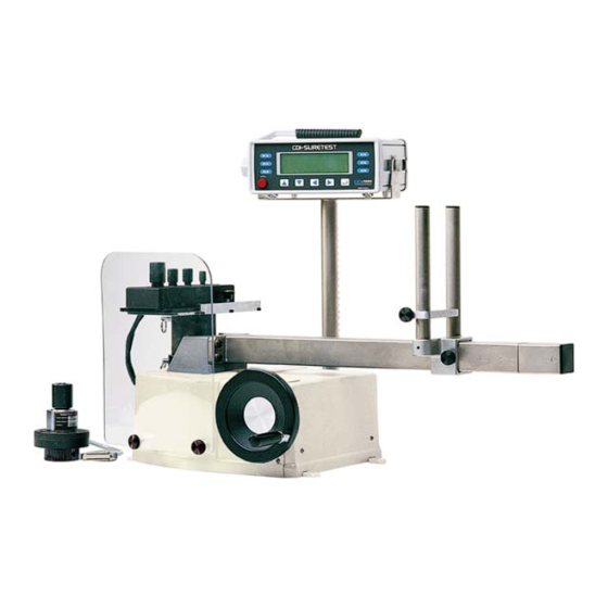
- Page 1 SURETEST AND 600TL Model 5000-3 Torque Calibration System USER’S MANUAL...
-
Page 2: Table Of Contents
2-12 • Transducers 2-13 • 600TL (LOADER) 2-14 Setup and Programming SURETEST Torque Calibration System Setup Back panel connections Setting Up the SURETEST System SURETEST Base Unit Controls Powering the Equipment Transducer Select Programming Setup • Setting up Date and Time •... - Page 3 5-14 Correction Factors on Test Weights 5-14 Gravitational Charts 5-15 600TL Manual Loader Application Torque Tester/Calibrator Types of Loader Testing • Torque Driver Testing Accessories SURETEST System Components and Inventory Control Optional Transducers and Accessories Calibration Accessories TABLE OF CONTENTS...
- Page 4 Using this Manual This manual contains instructions for use and setup of the SURETEST 5000-3 Torque Calibration System. A table of contents and a table of illustrations are provided to make this manual easy to use. Some of the information shown in text or illustrations is obtained using optional equipment.
- Page 5 DANGER Indicates an imminently hazardous situation which, if not avoided, will result in death or serious injury to the operator or to bystanders. WARNING Indicates a potential hazard which, if not avoided, could result in death or serious injury to the operator or to bystanders. CAUTION Indicates a potential hazard which, if not avoided, may result in minor or moderate injury to the operator or to bystanders.
-
Page 6: Safety Information
SAFETY INFORMATION Safety Information Important Safety Instructions This manual contains important safety and operating instructions for CDI 5000-3 Torque Calibration System. Refer to the information in this manual often for safe operation. Read All Instructions Read, understand and follow all safety messages and instructions in this manual and on the test equipment. - Page 7 SAFETY INFORMATION so the torque and load values are indicated on the display. The safety relays only work when the power is on. Flying particles can cause injury. WARNING Risk of entanglement. • When starting power tools, check for obstacles near your hand and anticipate the reaction force by gripping the tool firmly.
-
Page 8: Introduction
CLEAR, STORE and SEND functions can be set up for automatic or manual operation. The SURETEST stores and recalls up to 3000 torque readings and does statistical analysis on them for downloading to printer or computer. The statistical report (print out) includes a simple histogram for process monitoring. - Page 9 INTRODUCTION CHAPTER 1 The SURETEST operates directly from any AC power line between 100 VAC to 230 VAC, 50–60 Hz without the need for switch selection. A hard-wired lithium battery keeps the internal memory and date-time clock operating for up to 10 years. The real time clock is fully year 2000 compliant.
-
Page 10: Functional Description And Specifications
It is packaged in a compact, sturdy and attractive housing unit which requires little room on a laboratory bench. The SURETEST is typically used in conjunction with a Transducer and a 600TL bench top Mechanical Loader. -
Page 11: Front Panel
CHAPTER 2 SURETEST BASE UNIT Front Panel Figure 2-2 SURETEST Front Panel A- Membrane Function ( F1, F2, F3, F4, F5, F6 ), soft keys, and Cursor/Selection (Up (↑), Down (↓),Left (←), Right (→) and Enter (↵) Keys. B- Soft Key Menu: Zero, # Data Stored, Setup, Send, Store, Clear, Escape, Format. - Page 12 The number of the present data memory location. Front Panel Membrane Cursor and Function Keys The SURETEST is supported by a powerful Graphic User Interface (GUI). Set up, Command, or Control is done by selecting the appropriate Action Item on one of the provided Menus.
- Page 13 FUNCTIONAL DESCRIPTION AND SPECIFICATIONS CHAPTER 2 The SURETEST returns to the default menu from the measurements mode in the event there is no selection / input by the User for more than two minutes. This serves as a reminder for more (input) measurements.
- Page 14 Default: Min. Track 0.1% ; Min. Peak 1%. A warning message is first displayed. Upon confirmation by the User, the Default Settings will be loaded into the SURETEST. 5. Auto Settings Sets up CLEAR, STORE, and SEND functions. There are 2 options: Automatic or Manual.
- Page 15 Minute, or Second field. Then use Up (↑), Down (↓), cursor key to increment or decrement the respective value. Press and hold the cursor key to change the value quickly. Press ‘ENTER’ to activate the change. 8. Calibration This enables the User to perform calibration of the SURETEST base unit and transducers. (Refer to chapter 5).
- Page 16 For Manufacturer’s use only. 11. About This provides relevant information regarding the Manufacturer, the software version, and the serial number of the SURETEST device. 12. Other Features: Provides manual ZERO TARE. Stores present measurement to memory (Data 0001 in the example below).
- Page 17 FUNCTIONAL DESCRIPTION AND SPECIFICATIONS CHAPTER 2 Sets up memory clear options in RECALL mode. Recalls memory data to display. Format (F3) calls Statistical analysis to display. Send (F4). Send data to printer. Sends all memory data, statistical analysis and histogram to printer port. Sends data list with or without date-time stamp to computer / printer.
-
Page 18: Rear Panel (Input/Output)
FUNCTIONAL DESCRIPTION AND SPECIFICATIONS CHAPTER 2 SURETEST BASE UNIT Rear Panel (Input/Output) Figure 2-3 SURETEST Rear Panel Solenoid Control (Hirose RM15TRD-12S) (for use with optional 2000-600-02 Loaders) FUNCTION Loader Relay Common Loader Relay CCW Limit Loader Relay CW Limit Analog Output (BNC) Analog output provides a voltage level output that is directly proportional to transducer input, from -1.8V (full scale counter clockwise) to +1.8V (full scale clockwise). - Page 19 FUNCTIONAL DESCRIPTION AND SPECIFICATIONS CHAPTER 2 PRINTER PORT (DB-9P) FUNCTION Receive Transmit Ground OPTIONAL (DB-9P) FUNCTION Receive Transmit Ground TRANSDUCER INPUT (DB-37S) FUNCTION not used ground smart chip - bit 2 smart chip - bit 0 single xducer (-) signal single xducer (+) signal ground 4-in-1 xducer (-) signal 2...
-
Page 20: Transducers
LOW limit. It then produces a pulsating tone when the input torque exceeds the SET HIGH limit. The SURETEST Base Unit ignores inputs less than 0.1% of full range in TRACK mode, 1% in PEAK HOLD mode, 7% in FIRST PEAK and POWER TOOL modes. - Page 21 System Accuracy ±0.25% of reading @ 25°C with SURETEST Base Unit and transducer calibrated together. (SURETEST Transducers used with, but not calibrated to, another SURETEST Base Unit provide a system accuracy of ±0.5% of reading @ 25°C. Temperature Drift +0.03%/°C (+0.017%/°F).
- Page 22 FUNCTIONAL DESCRIPTION AND SPECIFICATIONS CHAPTER 2 Power Requirements 100-230 VAC, 50-60 HZ, 50 W, automatic voltage selection. Fused at 3.15 A. Environmental Operating Temperature: 10-32ºC, ( 50 to 90ºF) Storage Temperature: -20-50ºC, (-2 to 122ºF) Temperature Drift: +0.011%/ºC, (0.006%/ºF) Humidity: up to 85% non-condensing Weight 8.4 lbs.
- Page 23 Output torque 600 ft. lb. maximum 30º Rotation Dimensions 48.1” wide (with deflection beam fully extended), 26” high (with SURETEST on bracket), 29” deep (from crank handle open with SURETEST on bracket) Weight 65 lbs. Optional Calibration Fixturing (load arms and weights) ±0.05% accuracy...
-
Page 24: Setup And Programming
SETUP AND PROGRAMMING CDI 5000-3 TORQUE CALIBRATION SYSTEM SETUP Figure 3-1: CDI 5000-3 Torque Tester/Calibrator/Loader Setup Back panel connections 600TL Manual Loader SURETEST Base unit Smart 4-in-1 Transducer & Bracket adaptor Transducer cable Smart Single Transducer Analog Output Foot pedal switch... - Page 25 2. Install Pivot tube, Extension arm and Bracket. Adjust to desired position then lock using three setscrews shown on Fig. 3-2. 3. Install the SURETEST unit to the bracket and lock the unit using the two side knobs. 4. Install slide assembly (2100-0018), then lock using the side knobs as shown on Fig. 3-3.
-
Page 26: Suretest Base Unit Controls
Powering the Equipment To power the equipment, press the power button on the front of the SURETEST. • At POWER ON, the SURETEST performs a self-test and momentarily displays the results on the display. • With no transducer installed, the display then reads: •... - Page 27 SETUP AND PROGRAMMING CHAPTER 3 4-in-1 Transducer Installation When a 4-in-1 transducer is installed, the following is displayed: The Engineering Unit are in. lb. The Engineering Unit are ft. lb. All four transducers are scanned as indicated by their associated red LED indicators. To select one of the transducers, apply at least 5% of its full range torque.
-
Page 28: Setting Up Date And Time
Use HIGH and LOW Limits Alert to protect the tool under test or serve as a fastener installation torque preset alert. The SURETEST produces a constant audible tone when the input torque exceeds the LOW limit. It then produces a pulsating tone when the input torque exceeds the HIGH limit. - Page 29 SETUP AND PROGRAMMING CHAPTER 3 Press Enter (↵). The display reads: Press --> (F5) or <-- (F6) to select High or Low limit. Use Left (←) or Right (→) Cursor to select a digit to be changed. Increment or decrement the selected digit by pushing Up (↑) or Down (↓) cursor. Push and hold Up (↑) or Down (↓) Cursor to change the display quickly.
-
Page 30: Data List Memory
SETUP AND PROGRAMMING CHAPTER 3 To Program AUTO CLEAR, STORE, or SEND: Press (Setup). Scroll Down (↓) to select Auto settings. The display reads: Press Enter (↵). The display reads: Use Right (→) and Left (←) Cursor to position the reverse-video characters under the function being changed. -
Page 31: Clear Single Memory Location
Setting Up Printer Port The SURETEST is equipped with two RS-232 serial communications ports for use with an external printer or personal computer. The transfer rate is programmable (for printer port only) from 300 to 19.2K baud rate with 8 data bits, 1 stop bit and no parity. The recommended default is 19200 baud for Optional Port and 9600 for Serial Printer. - Page 32 SETUP AND PROGRAMMING CHAPTER 3 1. Press Setup 2. Scroll Down (↓) to select Edit Parameters 3. Press Enter (↵) the display read: 4. Press --> (F4) and <-- (F5) keys to select parameter to change. 5. Use Left (←) and Right (→) cursors to select digit to change. 6.
-
Page 33: Torque Calibration System Setup
TORQUE CALIBRATION SYSTEM SETUP CHAPTER 4 CHAPTER 4 CDI 5000-3 TORQUE CALIBRATION SYSTEM SETUP This chapter contains information on how to test, measure, and use the CDI 5000-3 Torque Calibration System. Testing Torque Wrenches and Drivers To use the CDI 5000-3 Torque Calibration System for torque wrench testing, a transducer of the appropriate range is fitted to the 600TL Manual Loader. -
Page 34: Dial And Bending Beam Torque Wrenches And Screwdrivers
Do not use this equipment with the power off. Always turn on the Base Unit so the torque values are indicated on the display. To program the SURETEST Base Unit refer to Chapter 3 Set Up and Programming to use HIGH and LOW limit alert, data STORE, display CLEAR, printer SEND and STATistical analysis features. -
Page 35: Adjustable Or Preset "Click" Wrenches And Screwdrivers
TORQUE CALIBRATION SYSTEM SETUP CHAPTER 4 Adjustable or Preset “Click” Wrenches and Screwdrivers Be sure the SURETEST transducer is capable of handling the intended torque to avoid damaging the transducer. WARNING Do not use this equipment with the power off. Always turn on the Base Unit so the torque values are indicated on the display. -
Page 36: Testing Power Tools
Be sure to operate any pneumatic or electrical power tool according to the manufacturer’s recommendations. Non-Impact Tools Be sure the SURETEST transducer is capable of handling the intended torque to avoid damaging the transducer. Always operate the system with the power on. WARNING Do not use this equipment with the power off. - Page 37 Remove the power tool. Loosen the joint rate simulator load screw. Repeat steps 7 through 9 twice again to exercise the tool-simulator assembly and the SURETEST transducer. Remove the power tool from the loader-transducer and press Zerotare. Press Select Mode to select POWER (TOOL) mode.
- Page 38 TORQUE CALIBRATION SYSTEM SETUP CHAPTER 4 tool clutch slips. Be careful not to add torque by turning the tool by hand. Release the torque and note the Power tool reading on the display. CLEAR the display. Repeat steps 4 through 15 in the opposite direction, if required. Given the variables typical of power tools and fastener joint dynamics, a number of readings should be taken and averaged to best determine the accuracy and repeatability for each tool.
-
Page 39: Statistical Analysis
CHAPTER 4 Statistical Analysis The SURETEST Base Unit accumulates torque measurements in a data list. The list is created with each auto or manual data store entry. Statistical analysis is calculated on the list and, if HIGH and LOW limits are established, draws a simple histogram of the results. -
Page 40: Printing Statistical Analysis
TORQUE CALIBRATION SYSTEM SETUP CHAPTER 4 Printing Statistical Analysis Press Data (F1) in select Transducer screen or (F2) in measurements mode. then Press Format (F3). Press Send (F4) to display the Print out menu. Use Down (↓) key to select Send Statistics then press Enter (↵) to Print. See example printout below. - Page 41 TORQUE CALIBRATION SYSTEM SETUP CHAPTER 4 ** R E S U L T ** Data : 0010 : 254.89 in-lb : 251.49 in-lb Range : 3.4039 in-lb Mean : 253.19 in-lb Sig.n : 0.9755 in-lb Sigma : 1.0283 in-lb : 0.5348 : 0.5317 %Err.
-
Page 42: Displaying Or Downloading Data List
TORQUE CALIBRATION SYSTEM SETUP CHAPTER 4 Displaying or Downloading Data List Torque measurements stored in the data list also include a date and time stamp. For additional information on setting up printer or PC ports, refer to Chapter 3—Set Up and Programming in this manual. -
Page 43: How To Use Analog Output (Rear Panel Bnc Connector)
CHAPTER 4 How to Use Analog Output (Rear Panel BNC Connector) Analog Output on the SURETEST provides a real time voltage level that is directly proportional to the torque applied to the transducer. It is useful for direct driving equipment such as analog plotters and chart recorders, or interfacing to a computer/controller with analog to digital (A/D) data acquisition capability. -
Page 44: Calibration
CHAPTER 5 CHAPTER 5 CALIBRATION The SURETEST Torque Calibration System is factory calibrated using precision torque test arms, certified weights and laboratory grade equipment. This chapter contains calibration instructions and information for the SURETEST System. Annual calibration is recommended. Calibration by the user is recorded in memory and voids factory certification. - Page 45 CALIBRATION CHAPTER 5 Torque Under 250 ft. lb. Mount the calibration block at the center of the stand with two 1/2-13 socket head cap screws with test bars that are 10" or shorter. Install these screws using the supplied torque wrench and 3/8-3/8 socket driver adapter.
- Page 46 Appropriate hangers and weights are listed in the calibration checkpoint table in this chapter. Notice that the weight of the hanger is included in all measurements. The hanger must be removed to set ZERO tare on the SURETEST Base Unit. 4-in-1 Transducer Mounting Detail for Calibration The 4-in-1 transducer mounts upright with integral transducers in the horizontal position.
-
Page 47: Quick Check
With the SURETEST ON, select TRACK mode, and select the UNITs of measure appropriate to the transducer as specified in the calibration checkpoint table in this chapter. - Page 48 CALIBRATION CHAPTER 5 Suggested Transducer Calibration Check Points, Bars, Hangers and Weights (Sheet 1 of 2) Part Hanger Calibration Check Weights to Add Total Range Length Weight Points Points (n) = more than 1 Weight 2000-4-02 5-50 in oz 2.5" none 5.0 in oz 5.0 in oz...
- Page 49 CALIBRATION CHAPTER 5 Suggested Transducer Calibration Check Points, Bars, Hangers and Weights (Sheet 2 of 2) Part Hanger Calibration Check Weights to Add Total Range Length Weight Points Points (n) = more than 1 Weight 2000-11-02 20-250 ft lb 10.0" 15 lb 20.0 ft lb (2) 2 lb, 5 lb...
- Page 50 New Transducer Calibration Improper calibration can result in torque measurement errors. Follow these procedures precisely. If an error is made in the procedure, turn the SURETEST off and begin again. Users are responsible for the results of their transducer calibration.
- Page 51 CALIBRATION CHAPTER 5 5222 Enter the following code into the display using the Cursor Keys: ( Left (←), Right (→) to select digit ; Up (↑), Down (↓) = increment/decrement value ; Enter (↵) to accept ) Calibration CW: Select Calibrate CW. Press ENTER (↵). A warning is displayed.
- Page 52 CALIBRATION CHAPTER 5 Press Unit (F2) key and select the desired torque unit. Using the Up (↑) and Down (↓) Cursor keys, enter the Full Scale value for the 4-in-1 transducer to calibrate. Possible values are: 50 in. lb. 400 in. lb. 1000 in.
- Page 53 CALIBRATION CHAPTER 5 Press (Accept) to accept the calibration value (1 Cal point). Apply 20% Torque = 10 in. lb. Press (Accept) to accept the calibration value (2 Cal point) . Apply 40% Torque = 20 in. lb. Press (Accept) to accept the calibration value (3 Cal point) .
-
Page 54: Suretest Base Unit Calibration
WARNING: Improper calibration can result in torque measurement errors. Follow these procedures precisely. If an error is made in the procedure, turn the SURETEST off and begin again. Users are responsible for the results of their calibration. Equipment • Laboratory grade millivolt meter for calibration measurements capable of resolving 1/100 millivolts. - Page 55 Program the measured voltage into the SURETEST Base Unit using the Cursor Keys. (Use Up (↑), Down (↓), Left (←) and Right (→) Cursor Keys to match the SURETEST display to the millivolt- meter). Then Press ENTER (↵) to accept.
- Page 56 CALIBRATION CHAPTER 5 Example: 08.0622 mV Program the measured voltage into the SURETEST Indicator as demonstrated in the example, “+08.0622” by pushing and holding the Up (↑) or Down (↓) Cursor keys. Press ENTER (↵). The display momentarily reads: Saved.
-
Page 57: Gravitational Effects
CALIBRATION CHAPTER 5 Gravitational Effects Correction Factors on Test Weights Weights used in torque calibration are affected by their acceleration due to: • Altitude above or below sea level, and • Latitude on earth between the equator and the poles. Test bars are not affected by these conditions. -
Page 58: Gravitational Charts
CALIBRATION CHAPTER 5 Gravitational Charts The charts in this section are taken from CRC Handbook of Chemistry and Physics, 58th Edition. CRC Press, Inc., 18901 Cranswood Parkway. Cleveland, Ohio 44128. Acceleration Due to Gravity for Sea Level at Various Latitudes Latitude, degrees Acceleration, cm/sec2 Latitude, degrees... -
Page 59: Application
2000-400-02, 4-in-1 transducers • 2000-500-02 Adapter Kit When the 600TL interfaces with the SURETEST unit and the 2000 series of torque transducers, the SURETEST Torque Calibration system provides precision loading, monitoring and data acquisition of torque, within ± 0.25% accuracy. -
Page 60: Torque Tester/Calibrator
B- 4-in-1 Transducer Standoff C- 600TL (Manual Loader) D- Side thumb screw E- 4-in-1 Adapter Bracket F- Multiple Transducers G- Drive Adaptors H- SURETEST Top thumb screw Tube, Load (Part of rest assembly) K- Rest, Adjustable L- Reaction Slide Assembly M- Safety shield... - Page 61 Drive Adaptor A drive adaptor couples the wrench to the transducer. Low torque 2000 series transducers use an internal- internal drive adaptor and high torque SURETEST transducers may use an adaptor/reducer. Transducer (Accessory) The loader accepts 2000 series single transducers directly. The 2000-400-02 4-in-1 transducer can be mounted using a 2000-500-02 adaptor kit.
- Page 62 MANUAL LOADER CHAPTER 6 Figure 6-2 Set up for Dial indicating, Deflection Beam and Micro-Adjustable Torque Wrenches. 1- Transducer Mounting A transducer facilitates the low-to-high ranges of the wrench under test. The transducer must be installed into the loader by lining up the red mark and securing it using two quick release pins. IMPORTANT The connector on single transducer cables contains the EEPROM calibration memory chip.
-
Page 63: Types Of Loader Testing
MANUAL LOADER CHAPTER 6 Types of Loader Testing Torque Driver Testing An optional torque screwdriver testing kit, is available for use in testing or calibrating most torque screwdrivers and "T" handled drivers. In addition to providing perfect driver-transducer alignment, it allows the use of the 600TL crank for precision torque application. Certain torque screwdrivers, "T"... - Page 64 ACCESSORIES APPENDIX A Appendix Accessories, included SURETEST 5000-3 Torque Calibration System Components Component Description 5000-ST SURETEST Digital Monitor 600TL Manual torque loader ¾ 2000-12-02 ” - 60 - 600 ft. lb. transducer with socket 2000-400-02 4-in-1 transducer kit Multiple transducer 1/4"...
- Page 65 ACCESSORIES APPENDIX A Appendix Accessories, optional Component Description 2000-4-02 1/4" ext. drive 5 – 50 in. oz. Transducer with socket 2000-5-02 1/4" ext. drive 15 - 200 in. oz. Transducer with socket 2000-6-02 1/4" ext. drive 4 -50 in. lb. Transducer with socket 2000-65-02 1/4"...
-
Page 66: Accessories
ACCESSORIES APPENDIX A Component Description 2000-50-1 Cable, Indicator to PC 950-79 Foot Pedal Switch (Data Send foot switch) 2000-50-2 Cable, Indicator to Serial Printer 2700-900-121 Cable, Smart Cable Replacement 2100-0750 Torque Screwdriver Testing Kit 900-0-1KIT Joint Rate Simulator; 50 in. lb. max. 900-2-01KIT Joint Rate Simulator;... -
Page 67: Calibration Accessories
ACCESSORIES APPENDIX A Calibration Accessories Calibration of the SURETEST Indicator and 2000 series transducers is recommended at least every 1 year. Component Description 2000-250-02 Calibration stand kit Includes: Stand Transducer mounting block ½ - 3/8" Square drive adaptor 1-1/4" Square drive adaptor 1-1/4"... - Page 68 19220 San Jose Ave. City of Industry, CA 91748-1497 FORM 20-2100-CDI...