Advertisement
Quick Links
Advertisement

Related Manuals for CDI TORQUE CDI-SURETEST


Summary of Contents for CDI TORQUE CDI-SURETEST
-
Page 2: Table Of Contents
TABLE OF CONTENTS Safety Information Introduction Functional Description and Specifications Functional Descriptions SURETEST Torque Calibration System Roll cabinet Front Panel Rear Panel (Input/Output) Torque Transducers 2-11 Specifications 2-12 SURETEST Torque Calibration System 2-12 Manual loader specifications 2-14 Setup and Programming SURETEST Torque Calibration System Setup Setting Up the Suretest System Suretest Controls... - Page 3 Suretest Indicator Torque Calibration 5-11 Gravitational Effects 5-14 Correction Factors on Test Weights 5-14 Gravitational Charts 5-14 2000-600-02 Manual Loader Application Torque Tester/Calibrator 2000-600-02 Manual Loader Loader Rear Panel Controls Ball Handle Adaptor 4-in-1 Transducer (Accessory) Extension Arm (Accessory) Types of Loader Testing Torque Driver Testing Torque Multiplier Testing Accessories...
- Page 4 Using this Manual This manual contains instructions for use and setup of the Suretest Torque Calibration System. A table of contents and a table of illustrations are provided to make this manual easy to use. Some of the information shown in text or illustrations is obtained using optional equipment.
- Page 5 DANGER Indicates an imminently hazardous situation which, if not avoided, will result in death or serious injury to the operator or to bystanders. WARNING Indicates a potential hazard which, if not avoided, could result in death or serious injury to the operator or to bystanders. CAUTION Indicates a potential hazard which, if not avoided, may result in minor or moderate injury to the operator or to bystanders.
-
Page 6: Safety Information
Safety Information Important Safety Instructions This manual contains important safety and operating instructions for CDI SURETEST Torque calibration system. Refer to the information in this manual often for safe operation. Read All Instructions Read, understand and follow all safety messages and instructions in this manual and on the test equipment. - Page 7 WARNING Risk of entanglement. • When starting power tools, check for obstacles near your hand and anticipate the reaction force by gripping the tool firmly. • Do not wear loose clothing and jewelry while operating a power tool. Loose clothes and jewelry can be caught in moving parts.
- Page 8 PRODUCT DESCRIPTION CDI-SURETEST MODEL 5000-ST The SURETEST is a laboratory grade instrument that provides TORQUE measurements. Although designed as an independent laboratory equipment, it can also be used in an integrated environment as the principal component of a Torque Calibration System. The...
-
Page 9: Introduction
CHAPTER 1 Introduction The SURETEST is a laboratory grade instrument that provides TORQUE measurements. Although designed as an independent digital indicator, it can also be used in an integrated environment as the principal component of a Torque Calibration System. The SURETEST features versatile data acquisition capabilities including measurement storage, retrieval, statistical analysis and automatic downloading to an external printer/computer. - Page 10 FUNCTIONAL DESCRIPTIONS AND SPECIFICATIONS CHAPTER 2 The SURETEST operates directly from any AC power line between 120VAC to 220 VAC, 50–60 Hz without the need for switch selection. A hard-wired lithium battery keeps the internal memory and date-time clock operating for up to 10 years. The real time clock is fully year 2000 compliant.
-
Page 11: Functional Description And Specifications
FUNCTIONAL DESCRIPTIONS AND SPECIFICATIONS CHAPTER 2 CHAPTER 2 Functional Descriptions and Specifications The SURETEST is CDI’s next generation Torque Measurement System. It provides exceptional accuracy and ease of use. It is packaged in a compact, sturdy and attractive housing unit which requires little room on a laboratory bench. The SURETEST is typically used in conjunction with a Transducer and a Mechanical Loader. -
Page 12: Roll Cabinet
FUNCTIONAL DESCRIPTIONS AND SPECIFICATIONS CHAPTER 2 The loader accepts all SURETEST series single transducers directly. Use a 2000-500-02 adapter kit to mount the optional 2000-400-02 4-in-1 transducer. For additional information refer to Appendix A–Accessories. Loader Use the 2000-600-02 Manual Loader for testing and calibrating all torque wrenches, drivers, torque multipliers, non-impact pneumatic and electric nut runners. -
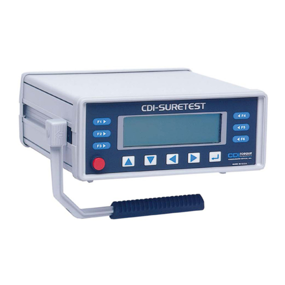
Page 13: Front Panel
FUNCTIONAL DESCRIPTIONS AND SPECIFICATIONS CHAPTER 2 FRONT PANEL Figure 2-3: SURETEST Front Panel A- Membrane Function ( F1, F2, F3, F4, F5, F6 ), And Cursor/Selection (Up, Down, Left, Right and Enter ) Keys. B- Soft Key Menu: Zero, # Data Stored, Setup, Send, Store, Clear, Escape, Format. C- Real Time Clock. - Page 14 FUNCTIONAL DESCRIPTIONS AND SPECIFICATIONS CHAPTER 2 SURETEST DISPLAY A 240 x 64 Full-featured Graphic LCD is used to provide versatile and clear displays of system menus as well as measurements. Characters and symbols are displayed in different fonts: • Maximum transducer range in the selected UNITS of measure. •...
- Page 15 FUNCTIONAL DESCRIPTIONS AND SPECIFICATIONS CHAPTER 2 The SURETEST always returns to the default menu from the measurements mode in the event there is no selection / input by the User. This serves as a reminder for more (input) measurements. Setup Mode The following Selections are available: 1.
- Page 16 FUNCTIONAL DESCRIPTIONS AND SPECIFICATIONS CHAPTER 2 Select Language Selects either English, German (Deutsch), French (Francais), Spanish (Espanol), or Portuguese (Portugues). Manufacturer’s Defaults: A warning message is first displayed. Upon confirmation by the User, the Default Settings will be loaded into the SURETEST. Auto Settings Sets up CLEAR, STORE, and SEND functions.
- Page 17 FUNCTIONAL DESCRIPTIONS AND SPECIFICATIONS CHAPTER 2 Edit Limits Sets up high torque limit preset. (->) to go Down 1 line. Sets up low torque limit preset. (<-) to go Up 1 line. Use Up or Down cursor key to increment or decrement the respective value. Use Left or Right cursor key to select digit.
- Page 18 FUNCTIONAL DESCRIPTIONS AND SPECIFICATIONS CHAPTER 2 9. EDIT PARAMETERS Sets up serial protocol function. Sets delay (in ms) per character upon printing. Sets delay (in ms ) per Linefeed. Minimum block-out with zero at 0.1% F.S. in Tracking Mode. Minimum block-out with zero at 1.0% F.S. in Peak-Hold Mode. 10.
-
Page 19: Rear Panel (Input/Output)
FUNCTIONAL DESCRIPTIONS AND SPECIFICATIONS CHAPTER 2 Rear Panel (Input/Output) Figure 2-5: SURETEST Rear Panel A- SOLENOID CONTROL (Hirose RM15TRD-12S) FUNCTION Loader Relay Common Loader Relay CCW Limit Loader Relay CW Limit ANALOG OUTPUT (BNC) Analog output provides a voltage level output that is directly proportional to transducer input, from -1.8V (full scale counter clockwise) to +1.8V (full scale clockwise). - Page 20 FUNCTIONAL DESCRIPTIONS AND SPECIFICATIONS CHAPTER 2 PRINTER PORT (DB-9P) FUNCTION Receive Transmit Ground OPTIONAL (DB-9P) FUNCTION Receive Transmit Ground TRANSDUCER INPUT (DB-37S) FUNCTION not used ground smart chip - bit 2 smart chip - bit 0 single xducer (-) signal single xducer (+) signal ground 4-in-1 xducer (-) signal 2...
- Page 21 FUNCTIONAL DESCRIPTIONS AND SPECIFICATIONS CHAPTER 2 SURETEST Transducers SURETEST transducers provide industry standard square drives. They feature a full bridge strain-gauge @ 350 Ohms nominal. Full range output is 1500 uE, 9mV (3mV/V @ 3.0V excitation). Torque transducers use a built-in EEPROM memory chip that stores range identification and calibration factors.
-
Page 22: Specifications
FUNCTIONAL DESCRIPTIONS AND SPECIFICATIONS CHAPTER 2 Specifications SURETEST Torque Calibration System System Accuracy ±0.25% of reading @ 25°C (Suretest and transducer calibrated together) SURETEST Transducers used with, but not calibrated to, another SURETEST provide a system accuracy of ±0.5% of reading @ 25°C. Temperature Drift +0.03%/°C (+0.017%/°F) Display Accuracy... - Page 23 FUNCTIONAL DESCRIPTIONS AND SPECIFICATIONS CHAPTER 2 Printer Serial Output Port Default: 9600 Baud Rate. Serial Communications RS-232 (true) 300—19.2K Baud 8 data bits 1 stop bit no parity Computer Serial COM Port (OPTIONAL) Default: 19,200 Baud Rate. RS-232 (True) Analog Output +(CW)/-(CCW) 1.8V at transducer full range linearity ±1% of reading Loader Control Relays...
-
Page 24: Manual Loader Specifications
SETUP AND PROGRAMMING CHAPTER 3 Manual Loader Specifications Input Torque (Hand Crank) 8 ft lb maximum (without Motorized control). Output Torque 2000 ft-lb ±20 degrees rotation maximum Power Requirements (safety solenoids) switching From 100 to 230VAC ±10%, @ 50-60 Hz. Weight (including 2000-100-02 Roll Cab) 1500 lbs. -
Page 25: Setup And Programming
SETUP AND PROGRAMMING CHAPTER 3 CHAPTER 3 SETUP AND PROGRAMMING TORQUE CALIBRATION SYSTEM SETUP SURETEST MANUAL LOADER 2000-600-02 MANUAL MECHANICAL LOADER ANALOG OUTPUT REAR PANEL CONTROLS FOOT PEDAL SWITCH 950-87 SOLENOID CONTROL CABLE POWER CABLES 110V/220 VAC 2000-117 PART NUMBER : 2000-114 ( U.S.A. - Page 26 SETUP AND PROGRAMMING CHAPTER 3 Back panel connections Manual Loader Solenoid control cable Suretest Smart 4-in-1 transducer Transducer cable Smart single transducer Analog Output Foot cable switch Power cables (110/220 VAC) Printer cable Personal computer cable Note: Cable (K) can be connected to Printer Port too. Setting Up the Torque Calibration System SURETEST...
-
Page 27: Suretest Controls
SETUP AND PROGRAMMING CHAPTER 3 Base Unit Controls SURETEST Refer to the illustration below when performing the power-up and programming procedures. Figure 3-2: SURETEST Controls – SURETEST Graphic LCD Display – Power Switch – Front Panel Membrane Function Keys Powering the Equipment To power the equipment, press the power button on the front of the SURETEST. - Page 28 SETUP AND PROGRAMMING CHAPTER 3 4-in-1 Transducer Installation When a 4-in-1 transducer is installed, the following is displayed: All four transducers are scanned as indicated by their associated red LED indicators. To select one of the transducers, apply at least 5% of its full range torque. To return to the scan mode, press ENTER.
-
Page 29: Programming Setup
SETUP AND PROGRAMMING CHAPTER 3 Programming Setup Setting up Date and Time Press (Setup). Scroll down to select Clock Adjust. Press ‘Enter’. The display reads: Use Left or Right Cursor to select the date/time element to be changed. Increment or decrement the date/time element by repeatedly pushing Up or Down Cursor. - Page 30 SETUP AND PROGRAMMING CHAPTER 3 Press ‘Enter’. The display reads: Press -> or <- to select Hi or Lo limit. Use Left or Right Cursor to select a digit to be changed. Increment or decrement the selected digit by pushing Up or Down Cursor. Push and hold Up or Down Cursor to change the display quickly.
-
Page 31: Data List Memory
SETUP AND PROGRAMMING CHAPTER 3 To use the AUTO CLEAR, STORE, or SEND: Press (Setup). Scroll down to select Auto settings. The display reads: Press ‘Enter’. The display reads: Use Right and Left Cursor to position the reverse-video (*) character under the function being changed. -
Page 32: Setting Up Printer/Pc Ports
TORQUE CALIBRATION SYSTEM SETUP CHAPTER 4 Clear Single Memory Location Use the procedure in this section to clear the a single memory location. Press (Data) to enter data list display. The display reads: Use the Up or Down Cursor to move to the current data. The units and present memory location are given on the top line. -
Page 33: Testing Torque Wrenches And Drivers
TORQUE CALIBRATION SYSTEM SETUP CHAPTER 4 CHAPTER 4 SURETEST TORQUE CALIBRATION SYSTEM SETUP This chapter contains information on how to test, measure, and use the SURETEST Torque Calibration System. Testing Torque Wrenches and Drivers To use the SURETEST Torque Calibration System for torque wrench testing, a transducer of the appropriate range is fitted to the 2000-600-02 Manual Loader. -
Page 34: Dial And Bending Beam Torque Wrenches And Screwdrivers
TORQUE CALIBRATION SYSTEM SETUP CHAPTER 4 Dial and Bending Beam Torque Wrenches and Screwdrivers Be sure the SURETEST transducer is capable of handling the intended torque to avoid damaging the transducer. WARNING Do not use this equipment with the power off. Always turn on the Base Unit so the torque values are indicated on the display. -
Page 35: Adjustable Or Preset "Click" Wrenches And Screwdrivers
TORQUE CALIBRATION SYSTEM SETUP CHAPTER 4 Adjustable or Preset “Click” Wrenches and Screwdrivers Be sure the SURETEST transducer is capable of handling the intended torque to avoid damaging the transducer. Always operate the system with the power on. WARNING Do not use this equipment with the power off. Always turn on the Base Unit so the torque values are indicated on the display. -
Page 36: Testing Power Tools
TORQUE CALIBRATION SYSTEM SETUP CHAPTER 4 Testing Power Tools The dynamic torque characteristic of a power tool and the static torque applied when using a wrench usually result in different torque readings. Spinning electric and pneumatic motor armatures contain inertia that produces a higher torque reading than what is actually absorbed by a practical fastener. - Page 37 TORQUE CALIBRATION SYSTEM SETUP CHAPTER 4 Figure 4-1: Power Tool Test Setup – Power Tool – Joint Rate Simulator – Transducer Couple the power tool to the joint rate simulator using the appropriate accessory adaptors and bit. While holding the power tool drive perfectly in-line with the transducer drive, energize the tool until its motor stalls or, if featured, the tool clutch slips.
- Page 38 TORQUE CALIBRATION SYSTEM SETUP CHAPTER 4 While holding the power tool drive perfectly in-line with the transducer drive, reinstall the tool onto the simulator and energize the tool until its motor stalls or, if featured, the tool clutch slips. Be careful not to add torque by turning the tool by hand. Release the torque and note the Power tool reading on the display.
-
Page 39: Displaying Statistical Analysis
TORQUE CALIBRATION SYSTEM SETUP CHAPTER 4 Displaying Statistical Analysis The SURETEST Base Unit accumulates torque measurements in a data list. The list is created with each AUTO or MANUAL data store entry. Statistical analysis is calculated on the list, and if SET HIGH and SET LOW limits are established, draws a simple histogram of the results. -
Page 40: Printing Statistical Analysis
TORQUE CALIBRATION SYSTEM SETUP CHAPTER 4 Printing Statistical Analysis Press Data , then Press Format. Press SEND to display the Print out menu. Use Down key to select Send Statistics then press Enter to Print. Press Escape to return to measurements mode. SPC PRINT-OUT _____________________ SPC listing... - Page 41 TORQUE CALIBRATION SYSTEM SETUP CHAPTER 4 ** R E S U L T ** Data : 0010 : 254.89 in-lb : 251.49 in-lb Range : 3.4039 in-lb Mean : 253.19 in-lb Sig.n : 0.9755 in-lb Sigma : 1.0283 in-lb : 0.5348 : 0.5317 %Err.
-
Page 42: Displaying Or Downloading Data List
TORQUE CALIBRATION SYSTEM SETUP CHAPTER 4 Displaying or Downloading Data List Torque measurements stored in the data list also include a date and time stamp. For additional information on setting up printer or PC ports, refer to Chapter 3—Set Up and Programming in this manual. -
Page 43: How To Use Analog Output (Rear Panel Bnc Connector)
CALIBRATION CHAPTER 5 How to Use Analog Output (Rear Panel BNC Connector) Analog Output on the SURETEST provides a real time voltage level that is directly proportional to the torque applied to the transducer. It is useful for direct driving equipment such as analog plotters and chart recorders, or interfacing to a computer/controller with analog to digital (A/D) data acquisition capability. -
Page 44: Calibration
CALIBRATION CHAPTER 5 Annual calibration is recommended. Calibration by the user is recorded in memory and voids factory certification. Contact your authorized CDI sales representative for calibration and repair services. If extreme calibration precision is required, refer to Correction Factors on Test Weights in this chapter. Mounting Details Single Transducer Mounting Detail for Calibration Single transducer calibration requires the use of a reaction stand and... - Page 45 CALIBRATION CHAPTER 5 Torque Under 250 ft lb Mount the calibration block at the center of the stand with two 1/2-13 socket head cap screws with test bars that are 10" or shorter. Install these screws using the supplied torque wrench and 3/8-3/8 socket driver adapter.
- Page 46 CALIBRATION CHAPTER 5 WARNING Always position the 40" arm over the front of the stand as shown. Never extend the test arm behind the stand because the stand will tip over when weights are applied. The 40" test arm is coupled to the 2000-13-02, 1000 ft lb, and 2000-14-02, 2000 ft lb transducers using a 1-1/4"...
-
Page 47: Quick Check
CALIBRATION CHAPTER 5 The 4-in-1 transducer may also be mounted to the calibration stand, shown in Figure 5-2, using the standoff fixture and bracket assembly. For this mounting configuration the two slide knobs must be loosened and four 5/16-18 bolts attached to secure the 4-in-1 transducer to the bracket assembly. Quick Check WARNING Always be alert to the potential for personal injury that may be caused by excessive... - Page 48 CALIBRATION CHAPTER 5 Suggested Transducer Calibration Check Points, Bars, Hangers and Weights (Sheet 1 of 2) Part Hanger Calibration Check Weights to Add Total Range Length Weight Points Points (n) = more than 1 Weight 2000-5-02 15-200 in oz 2.5" none 15.0 in oz 2 oz, 4 oz...
- Page 49 CALIBRATION CHAPTER 5 Suggested Transducer Calibration Check Points, Bars, Hangers and Weights (Sheet 2 of 2) Part Hanger Calibration Check Weights to Add Total Range Length Weight Points Points (n) = more than 1 Weight 2000-12-02 60-600 ft lb 40" 15 lb 60.0 ft lb 60.0 ft lb...
- Page 50 CALIBRATION CHAPTER 5 Torque Calibrations SURETEST New Transducer Calibration Improper calibration can result in torque measurement errors. Follow these procedures precisely. If an error is made in the procedure, turn the Suretest off and begin again. Users are responsible for the results of their transducer calibration.
- Page 51 CALIBRATION CHAPTER 5 5222 Enter the following code into the display using the Cursor Keys: ( Left / Right to select digit ; Up / Down = Increment / Decrement value ; ‘Enter’ to accept) Calibration CW: Select Calibrate CW. Press ‘ENTER’. A warning is displayed.
- Page 52 CALIBRATION CHAPTER 5 Press F2 key and select the desired torque unit. Using the Up and Down Cursor keys, enter the Full Scale value for the 4-in-1 transducer to calibrate. Possible values are: 50 in-lb 400 in-lb 1000 in-lb 250 ft-lb ( For 4 in 1 Transducers display shows : CHECKING TRANSDUCER.) Apply load until “...
- Page 53 CALIBRATION CHAPTER 5 Press (Accept) to accept the calibration value (1 Cal point). Apply 20% Torque = 10 in.lb Press (Accept) to accept the calibration value (2 Cal point) . Apply 40% Torque = 20 in.lb Press (Accept) to accept the calibration value (3 Cal point) .
-
Page 54: Suretest Indicator Torque Calibration
CALIBRATION CHAPTER 5 All readings show minus sign (-). Press F1 twice to return to measurement mode. SURETEST Indicator Calibration WARNING: Improper calibration can result in torque measurement errors. Follow these procedures precisely. If an error is made in the procedure, turn the Suretest off and begin again. - Page 55 CALIBRATION CHAPTER 5 Use DOWN Cursor key to scroll down to Calibration Item. Press ‘ENTER’. The display reads: 5111 Enter the following code into the display using the Cursor Keys: ( Left / Right to select digit ; Up / Down = Increment / Decrement value ; ‘Enter’ to accept) Calibrate tester Using a laboratory millivolt meter, measure the voltage across pin 2 (ground) and 19 (Gage Excitation) of the calibration fixture.
- Page 56 CALIBRATION CHAPTER 5 Using a laboratory millivolt meter, measure the voltage across pins 5 and 6. Example: 08.0622 mV Program the measured voltage into the SURETEST Indicator as demonstrated in the example, “+08.0622” by pushing and holding the Up or Down Cursor keys. Press ENTER.
-
Page 57: Gravitational Effects
MANUAL LOADER CHAPTER 6 Gravitational Effects Correction Factors on Test Weights Weights used in torque calibration are affected by their acceleration due to: • Altitude above or below sea level, and • Latitude on earth between the equator and the poles. Test bars are not affected by these conditions. - Page 58 MANUAL LOADER CHAPTER 6 -0.1543 -0.1852 -0.2160 -0.2469 -0.2777 Correction Factor for Check Point Readings Determine latitude and altitude. Obtain information from local geological survey office or library. Find the acceleration due to gravity for sea level from its chart. Subtract the free air correction for altitude from its chart.
-
Page 59: Application
MANUAL LOADER CHAPTER 6 Application The loader is a laboratory grade instrument used for testing and calibrating all torque wrenches, drivers, torque multipliers, non-impact pneumatic and electric nut runners Power To activate the limit solenoids that protect the transducers from overload, the loader requires AC power, 115/230VAC, 50 to 60 Hz, 1.0 amps. -
Page 60: Torque Tester/Calibrator
MANUAL LOADER CHAPTER 6 Functional Description This section describes major hardware components of the torque tester, including the: • Torque tester calibrator, • 2000-600-02 Manual Loader, • Loader rear panel controls, • Ball handle adaptor, • 4-in-1 transducer (accessory), and •... - Page 61 MANUAL LOADER CHAPTER 6 Use the 2000-600-02 Manual Loader to test torque wrenches. Refer to Figure 6-2 for an exploded view of the Loader and components. Figure 6-2: 2000-600-02 Manual Loader, Exploded View A- Transducer Mounting A transducer facilitates the low-to-high ranges of the wrench under test. The transducer must be installed into the loader by lining up the red mark with the "TORQUE"...
- Page 62 MANUAL LOADER CHAPTER 6 IMPORTANT The connector on single transducer cables contains the EEPROM calibration memory chip. Never attempt to remove the connector from the transducer. B- Hand Crank Turn hand crank on the loader to apply torque. 2000 ft lbs of torque are generated with only 8 ft- lbs of manual torque applied.
-
Page 63: Loader Rear Panel Controls
MANUAL LOADER CHAPTER 6 Loader Rear Panel Controls The 2000-600-02 Manual Loader rear panel is shown in Figure 6-3. Figure 6-3: 2000-600-02 Manual Loader Rear Panel Controls A- Fuse The loader power supply is protected with a 1 amp slo-blow fuse. B- Voltage Select A selector switch allows the loader to use both 110VAC or 220VAC. -
Page 64: Ball Handle Adaptor
MANUAL LOADER CHAPTER 6 Ball Handle Adaptor Wrenches featuring a ball handle are fixtured using the ball handle reaction adaptor shown in Figure 6-4. Install the adaptor onto the reaction slide using both reaction pins. Fix the adaptor height with the threaded knob. Figure 6-4: Ball Handle Adaptor 6-63... -
Page 65: 4-In-1 Transducer (Accessory)
MANUAL LOADER CHAPTER 6 4-in-1 Transducer (Accessory) The 4-in-1 transducer is mounted to the loader using the standoff fixture and bracket assembly as shown in Figure 6-5. Figure 6-5: 4-in-1 Transducer on 2000-600-02 Manual Loader A- Quick Release Pins Four quick release pins must be installed. The first two secure the standoff fixture to the loader and the second two lock the adaptor to the transducer bracket. - Page 66 MANUAL LOADER CHAPTER 6 E- 4-in-1 Adapter Bracket Holds the 4-in-1 transducer horizontal to the loader. 6-65...
-
Page 67: Extension Arm (Accessory)
MANUAL LOADER CHAPTER 6 Extension Arm (Accessory) The 2000-600-02 Manual Loader accepts torque wrenches up to 80" in length. The extension arm is attached as shown in Figure 6-6. A quick release pin is used at the end of the arm to capture the reaction pin slide assembly. -
Page 68: Types Of Loader Testing
ACCESSORIES APPENDIX A Types of Loader Testing Torque Driver Testing An accessory torque screwdriver testing kit, 2000-750-02, is available for use in testing or calibrating most torque screwdrivers and "T" handled drivers. In addition to providing perfect driver-transducer alignment, it allows the use of the 2000-600-02 loader crank for precision torque application. -
Page 69: Accessories
ACCESSORIES APPENDIX A Figure A-1: Roll Cabinet Drawer Arrangement A-68... - Page 70 ACCESSORIES APPENDIX A SURETEST Torque Calibration System Components and Inventory Control Component Description Drawer-Cutout 2000-100-02* Roll cabinet 2000-100-2 Foam insert 2000-100-3 Foam insert 2000-100-4 Foam insert 2000-100-5 Foam insert 2000-100-7 Foam insert 2000-100-8 Foam insert 2000-600-02 Manual torque loader 2000-600-10 Loader 2000-560 Plexiglass safety shield...
-
Page 71: Optional Transducers And Accessories
ACCESSORIES APPENDIX A Optional Transducers and Accessories Component Description Drawer-Cutout 2000-5-02 1/4" ext. drive 15-200 in oz transducer 342-40 1/4" internal adaptor 2000-6-02 1/4" ext. drive 4-50 in lb transducer 342-40 1/4" internal adaptor 2000-65-02 1/4" ext. drive 15-150 in lb transducer 342-40 1/4"... - Page 72 ACCESSORIES APPENDIX A Component Description Drawer-Cutout 2000-550-02 Extension arm kit, for up to 80" wrenches 2000-550-108 Arm 2000-550-115 Reaction pin slide block assembly 2000-195-1 Retention pin 2000-50-1 Cable, Indicator to PC 2000-50-2 Cable, Indicator to serial printer 2000-900-121 Cable, smart cable replacement 2000-750-02 Torque screwdriver testing kit 900-0...
-
Page 73: Calibration Accessories
ACCESSORIES APPENDIX A Calibration Accessories Calibration of the 2000-610-02 Indicator and SURETEST series transducers is recommended at least every 1 year. Component Description Drawer-Cutout 2000-250-02 Calibration stand kit 2000-250-0 Stand 2000-150-02 Transducer mounting block 2000-152-3 3/8" Square drive adaptor S2000-221-0 1-1/4"... - Page 74 ACCESSORIES APPENDIX A Component Description Drawer-Cutout Weights 2500-310-1 0.3 oz Hook (1) 2500-310-2 0.5 oz Hook (1) 2000-310-2 2 oz Bob (1) 2000-310-3 4 oz Bob (1) 2000-300-2 1/2 lb Disk (1) 2000-300-3 1 lb Disk (2) 2000-300-4 2 lb Disk (4) 2000-300-5 5 lb Disk (6) 2000-300-6...