
Related Manuals for Quantrax Computherm E Series


Summary of Contents for Quantrax Computherm E Series
- Page 1 COMPUTHERM E280FC programmable digital Wi-Fi fan coil thermostat for 2- and 4-pipe systems Operating instructions COMPUTHERM E Series...
-
Page 3: Table Of Contents
TABLE OF CONTENTS 1. A general description of the thermostat 2. Important warnings and safety recommendations 3. Information appearing on the display of the thermostat 4. Functions accessible in the phone application 5. Location of the thermostat 6. Connection and installation of the thermostat 6.1. - Page 4 10. Operation-related settings 10.1. Selecting the temperature sensor (DIF) 10.2. Calibration of the temperature sensor (ADJ) 10.3. Antifreezing (FRE) 10.4. Memorizing settings in the event of a power failure (PON) 10.5. Switching between heating, cooling and ventilation modes (FUN) 10.6. Fan tempereture based control (FAN) 10.7.
-
Page 5: A General Description Of The Thermostat
1. A GENERAL DESCRIPTION OF THE THERMOSTAT The COMPUTHERM E280FC Wi-Fi fan coil thermostat is a device that can be operated by a smartphone or tablet via Internet, and especially recommended for controlling fan coil heating or cooling systems. It can be easily connected to any 230 V operational fan coil devices with three fan speed, and valve adjusters opening and closing the valves. -
Page 6: Important Warnings And Safety Recommendations
your holiday home during the heating season as well. The two parallel operating relays incorporated into the device simply ensure that the thermostat also opens/closes the valve of the heating/ cooling pipeline and controlls the fan coil fan. (figure 3) 2. - Page 7 • The manufacturer will assume no responsibility for any possib le direct or indirect damages or income losses incurring during the use of the device. • The device will not work without power supply, but the thermostat is able to memorize settings. In case of power failure (outage) it can resume operation without any external inter vention after the power supply is restored, provided that this option has been chosen among settings (see Chapter...
- Page 8 that some functions of the device and the applications operate and appear in a way other than described in these instructions for use. - 8 -...
-
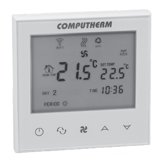
Page 9: Information Appearing On The Display Of The Thermostat
3. INFORMATION APPEARING DISPLAY OF THE THERMOSTAT Figure 1. - 9 -... -
Page 10: Functions Accessible In The Phone Application
4. FUNCTIONS ACCESSIBLE IN THE PHONE APPLICATION Figure 2. - 10 -... -
Page 11: Location Of The Thermostat
5. LOCATION OF THE THERMOSTAT It is expedient to install the thermostat on the wall of a room used regularly or for a prolonged stay, so that it is located in the direction of natural air movement in the room, but do not expose it to draughts of air or extreme heat effects (e.g. -
Page 12: Connection Of The Device(S) To Be Controlled
6.1. Connection of the device(s) to be controlled The fan coil device to be controlled and the valve adjusters must be connected to the terminal block on the back of the product. The fan coil device must be connected to the Low, Med and Hi (low, medium and high fan speed) outputs of the relays in the thermostat and the valve adjusters to the outputs of Valve1 and Valve2. -
Page 13: Connection To The Electrical Network
6.2. Connection to the electrical network The product should be connected to the 230 V network through a two core cable. Power supply should be connected to points N and L of the terminal block located on the rear side of the thermostat. You do not have to take care of phase correctness during the connection process (Figure 3). -
Page 14: Internet Control Setup
7. SETTING UP THE INTERNET CONTROL 7.1. Installing the application The thermostat can be controlled by both a smartphone and a tablet with the help of free application COMPUTHERM E Series. Application COMPUTHERM E Series can be downloaded to iOS and Android operating systems. -
Page 15: Connecting The Thermostat To A Wi-Fi Network
On your phone/tablet switch on Wi-Fi connection. Join to the 2.4 GHz Wi-Fi network to be used for the thermostat. • Activate the positioning (GPS location) feature on your phone. • Start the COMPUTHERM E Series application. - 15 -... - Page 16 • Give all the requested permissions to the application in order to work properly. • Turn off the device by tapping button on the thermostat. • Touch and hold the button for approx. for 10 seconds until symbol on the display flashes quickly. •...
-
Page 17: Connecting The Thermostat To A User Account
of the thermostat the symbol starts to illuminate continuously. 7.3. Connecting the thermostat to the application • You can search for COMPUTHERM thermostats E series connected to the Wi-Fi network concerned by tapping the “Search” icon in the left bottom corner (i.e. this requires that the thermostat is connected to the same Wi-Fi network used for the phone). - Page 18 • Connect your smartphone/tablet to the Wi-Fi network to which the COMPUTHERM thermostat has been E280FC con nected. • On the apparatus you want to use for controlling download then start application COMPUTHERM E Series • Tapping the “Search” icon in the left bottom corner, the phone/table will search COMPUTHERM E Series thermostats connected to the Wi-Fi network concerned.
-
Page 19: The Basic Operation Of The Hermostat
8. BASIC OPERATION OF THE THERMOSTAT When switched on, the thermostat controls the connected device(s) fan coil and valve adjuster) based on the measured and cur rently set (manually or programmed) temperature, the switch ing sensitivity of the thermostat (factory default ± 0.2 °C). This means that if the thermostat is set to heating mode and 22 °C, at a switching sensitivity of ±0.2 °C, the thermostat’s output re lays will close at temperatures below 21.8 °C and opened at... -
Page 20: Basic Settings
and the power supply of the device is interrupted within a few seconds, the modified settings will not necessarily be saved. 9. BASIC SETTINGS After the application has been started, COMPUTHERM E series thermostats assigned to the application concerned appear on page “My Thermostat’s”. -
Page 21: Deleting The Thermostat Assigned To The Application
Tapping the “Lock current thermostat” icon, here you can disable matching the application for other users. Until this function is unlocked the thermostat can only be used by users who have already added the device to their application, and new users will not be able to join the device through the Wi-Fi network. -
Page 22: Locking Operating Buttons
application after the thermostat has been selected. Now the thermostat sets date and time automatically via Internet. • On the thermostat: While the thermostat is on, tap the button on the thermostat. Then the numbers indicating the hour are flashing on the display. -
Page 23: Operation-Related Settings
application after the thermostat has been selected. Henceforward the device cannot be controlled by the touch buttons on the thermostat until the operating buttons are unlocked. To unlock the operating buttons tap the icon again in the phone application. • On the thermostat: While the thermostat is turned on, tap and hold the button... - Page 24 • On the thermostat: - Turn off the device by tapping the button. - Tap and hold the button and, at the same time, touch button for a short time. - Now you enter the settings menu: in the right bottom corner ...
- Page 25 The setting options are shown in the table below: Options Default Detailed Display Function Setting Setting Description Selecting switching sensitivity ±0.1 – ±1.0 °C ±0.2 °C Chapter 10.1. Defining maximum settable 5 – 99 °C 35 °C ---- temperature Defining minimum settable 5 –...
-
Page 26: Selecting The Temperature Sensor (Dif)
10.1. Selecting switching sensitivity (DIF) It is possible to set the switching sensitivity. By setting this val ue, you can specify how much the appliance switches the outputs on/off below/above the set temperature. The lower this value, the more consistent the internal room temperature, the greater the comfort is. -
Page 27: Antifreezing (Fre)
10.3. Antifreezing (FRE) When the antifreezing function of the thermostat is activated, the thermostat will switch on its output, regardless of any other setting, when the temperature measured by the thermostat goes below ±3 °C. When the temperature reaches 7 °C, normal operation of the output is restored (according to the set temperature). -
Page 28: Switching Between Heating, Cooling And Ventilation Modes (Fun)
10.5. Changing between heating, cooling and ventilation mode (FUN) You can easily switch between heating (00; factory default), cooling (01) and ventilation (02) modes. The connection points of the thermostat output relays close at a temperature below the set temperature in heating mode and at a temperature above the set temperature in cooling mode (taking into account the set switching sensitivity). -
Page 29: Programmable Fan Speed (Pfs)
fan operates continuously in the set speed. When the function is on (01; factory default setting), the fan and valve outputs are switched on at the same time, and if heating/cooling is not needed, both outputs are switched off. 10.7. Programozott üzemmódhoz tartozó ventilátorfokozat (PFS) In programmed mode, the thermostat controls the fan according to a preset fan speed. -
Page 30: Restoring Default Setting (Fac)
appropriate setting. In the case of two-pipe systems, when the thermostat gives a heating/cooling command, the 230 V mains voltage is displayed on both Valve1 and Valve2 outputs. In the case of four-pipe systems, in heating mode, only the Valve1 output is switched on in the event of a heating command, while Valve2 is continuously switched off. -
Page 31: Switching Between On And Off Positions
11. SWITCHING BETWEEN ON AND OFF POSITIONS AND MODES OF THE DEVICE The thermostat has the following 2 positions: • Off position • On position You can switch between off and on positions in the following way: • Using phone application: by tapping the icon. -
Page 32: Manual Mode
You can switch between the modes in the following way: • Using phone application: by touching the icons. • On the thermostat: touching the button. The currently selected mode is indicated as follows: • In the phone application: manual mode by the , icon and programmed auto mode by the icon. -
Page 33: Programmed Auto Mode
The currently set temperature can be modified in the following way: • Using phone application: ͦ with the icons. ͦ amoving the slide (oval) on the circular scale • On the thermostat: with the buttons. The currently set fan mode be modified in the following way: •... -
Page 34: Description Of The Steps Of Programming
The device can be programmed for a period of one week. In the programmed auto mode the thermostat operates automatically, and cyclically repeats the entered switches every 7 days. The following 3 options are available to program the thermostat: • 5+2 mode: setting 6 switches per day for 5 working days and 2 switches per day for 2 days of the weekend. - Page 35 switch be tween programming modes as follows: - 12345,67: 5+2 mode - 123456,7: 6+1 mode - 1234567: 7+0 mode c) Switches belonging to a given programming mode are below the indication of the programming mode. You can modify data (time, temperature) of switches by tapping the value concerned.
- Page 36 b) With the buttons choose the preferred programming mode as follows: - for 5+2 mode: 12345 - for 6+1 mode: 123456 - for 7+0 mode: 1234567 Now touch the button again. c) Following this, you can specify or modify various switching times and temperatures as follows: - You can switch between switching times with the button.
-
Page 37: Program Change Until The Next Switch In The Program
Attention! During programming, the switching times can only be changed so that they remain in chronological order. 11.2.3. Modifying programme until the next switch in the program If the thermostat is in programmed mode, but you want to temporarily change the set temperature until the next program switch, you can do so as follows: •... -
Page 38: Practical Advices
12. PRACTICAL ADVICES, SOLVING ANY PROBLEMS THAT MAY OCCUR Problem with the Wi-Fi connection When the product cannot be connected to a Wi-Fi network or cannot be controlled via the Internet because the connection between the product and the Internet interface is lost and the application indicates that the device is not available, we recommend to check the list of Frequently Asked Questions (FAQs) collected on our website and follow the steps described... - Page 39 FREQUENTLY ASKED QUESTIONS When you think that your appliance is operating incorrectly or encounter any problem while the appliance is being used then we recommend that you read Frequently Asked Questions (FAQ) available on our website, where we collected the prob lems and questions that most frequently occur while our appli ances are being used, along with the solutions thereto: http://www.computherm.info/en/faq...
-
Page 40: Technical Data
13. TECHNICAL DATA • Trademark: COMPUTHERM • Model identifier: E280FC • Temperature control class: Class I. • Contribution to the efficiency of seasonal space heating: 1 % • Temperature measuring range: 0 °C - 50 °C (0.1 °C steps) • Temperature measurement accuracy: ±0.5 °C •... - Page 41 • Protection against environmental impacts: IP20 • Standby power consumption: max 0.5 W • Dimensions: 86 x 86 x (17+33) mm • Mass: thermostat: 185 g • Type of the temperature sensor: NTC 3950 K 10 kΩ at 25 °C - 41 -...
- Page 43 RED 2014/53/EU and RoHS 2011/65/EU directives. QUANTRAX Ltd. Manufacturer: Fülemüle u. 34., Szeged, H-6762, Hungary Phone: +36 62 424 133 • Fax: +36 62 424 672 E-mail: iroda@quantrax.hu Web: www.quantrax.hu • www.computherm.info Origin: China Copyright © 2023 Quantrax Ltd. All rights reserved.
Need help?
Do you have a question about the Computherm E Series and is the answer not in the manual?
Questions and answers