Table of Contents
Advertisement
Quick Links
Advertisement
Table of Contents

Related Manuals for SanRex CALPOTE UG Series


Summary of Contents for SanRex CALPOTE UG Series
- Page 1 UG1 INSTRUCTION MANUAL Thank you for your purchase of our Thyristor Type Power Regulator Unit CALPOTE UG1 Series. In order to use this product safely and correctly, read this instruction manual thoroughly before using this product. Ensure that this manual is passed to the end user of this product.
-
Page 2: Table Of Contents
TABLE OF CONTENTS SAFETY PRECAUTIONS ......................5 Usage/Storage Location ............................7 Installation ..................................7 Wiring ....................................8 Maintenance/Inspection ............................8 PRECAUTIONS DURING USAGE ..................9 CHECKING THE PRODUCT ..................... 11 UNIT CONNECTION DIAGRAM ..................13 EXTERNAL CONNECTIONS OF THE UNIT ............14 Control Terminal Block ............................ - Page 3 Er.02: Temperature Rise Error ........................54 Er.03: Fuse Blowout .............................. 54 Er.07: CPU Error ............................... 55 Er.08: Memory Error ............................... 55 Er.09: Emergency Stop ............................55 Er.10: Power Supply Voltage Drop ......................55 Er.11: Instantaneous Voltage Drop ......................55 Er.12: Frequency Error ............................56 8.10 Er.13: Heater Disconnection ..........................
- Page 4 14 UNIT SPECIFICATIONS ......................85 15 OPTIONAL ITEM SPECIFICATIONS ................87 APPENDIX A. PARAMETER LIST ................... 89 APPENDIX B. PANEL TRANSITION DIAGRAM ............ 94 APPENDIX C. ERROR CODE LIST .................. 95...
-
Page 5: Safety Precautions
SAFETY PRECAUTIONS Read this instruction manual to ensure that work is performed correctly and safely. In order to prevent injury to people, and to prevent damage to property, the following label categories and symbols are used to explain the items that must be observed. Explanation of label categories This indicates information that involves the risk of death or serious WARNING... - Page 6 Installation, wiring, maintenance, and inspection must all be performed by contractors who specialize in this work. Before installing, wiring, maintaining, and inspecting this product, turn OFF the input power supply of the distribution panel and check that the power supply is OFF. ...
-
Page 7: Usage/Storage Location
1.1 Usage/Storage Location Do not use or store the product in locations such as the following. There is the risk of fire due to factors such as product failure, damage, and deterioration if this instruction is not followed. Hot, cold, or humid locations that are not in compliance with the operating environments specified by the instruction manual. -
Page 8: Wiring
1.3 Wiring Use wires whose dielectric strength corresponds to the circuit voltage. There is the risk of electric shock if you use wires without dielectric strength. Fully cover the input and output terminals and the conducting parts of the wires with tubes, tape, or other such insulating objects. -
Page 9: Precautions During Usage
PRECAUTIONS DURING USAGE Pay attention to the following when using the unit. The main circuit thyristor may be damaged in short circuit mode. To prevent fire and property damage in case of ground faults, ensure that the design is safe by, for example, installing protective functions on the power input side of the unit main circuit using breakers or other devices. - Page 10 A load must be connected during test operation. When test operation is performed with no load, voltage continues to be applied to the output terminal. Additionally, do not perform test operation with no load while the external potential transformer (PT) is connected. Doing so may damage the unit.
-
Page 11: Checking The Product
CHECKING THE PRODUCT Check the following before installation. Check that the product and parts with the correct specifications are included as ordered. Included item name Quantity UG1 unit Screws, nuts, etc. for output wiring (1) Screw For models with a rated current of 25 to 250 A (2) Bolt (3) Washer... - Page 12 Check that the optional items with the correct specifications are included as ordered. For included items, refer to the installation manual that comes with each optional item. Optional item Model Optional item that needs to be purchased separately Display panel UG-DP Extension cable Conversion...
-
Page 13: Unit Connection Diagram
UNIT CONNECTION DIAGRAM Display circuit PCB3 Conversion CN502 board UG-TB Control board PCB1 CN503 Communication board UG-CL UG-MB Power supply, gate board PCB2 THS1 FAN1 THY1 Snubber circuit PCB4 Power supply Load Thyristor Current transformer Cooling fan (air-cooled models only) Printed circuit board Fuse (only models with a fuse) Connector... -
Page 14: External Connections Of The Unit
EXTERNAL CONNECTIONS OF THE UNIT 5.1 Control Terminal Block Wire the control terminal block of the unit according to the following table. (Terminal screw: M3) Terminal Description about functions and purposes When not in use The inputs for the control power supply. These terminals need –... - Page 15 Terminal Description about functions and purposes When not in use VF2: Gradient (proportional) signal input Short-circuited with VE3 VH2: Manual (upper limit) signal input Open VL2: Lower point (lower limit) signal input Short-circuited with VE1 VE3 – VE1: +5 VDC output for a variable resistor ↑...
- Page 16 Terminal Description about functions and purposes When not in use Start/stop switching signal input Open • Short-circuited: Starts operation. The output is gradually increased during the soft-start time. • Open: Stops operation. In the phase control, the output is gradually decreased during the time specified with the soft-start time.
-
Page 17: Connection Diagrams For Setting Methods
Temperature V E 3 controller (current source) V F2 Temperature V H 2 controller (voltage source) V L 2 Subsequent units V E 1 -15V 210V Layout of the control terminal block Terminal block connection example 5.2 Connection Diagrams for Setting Methods (1) Manual adjustment (2) Two-position control (3) Automatic adjustment 1 (4 to 20 mA [DC]) - Page 18 Manual adjustment Set [F101: Temperature controller type] to [0: 4 to 20 mA (1 to 5 VDC)]. (1) Standard (2) With the gradient setting Gradient Manual Manual (3) With the lower point setting (4) With the gradient setting and the lower point setting Gradient Manual Manual...
- Page 19 (2) Two-position control Set [F101: Temperature controller type] to [2: Two-position control]. (1) Standard (2) With the proportional setting Ratio Upper Upper limit limit Lower Lower limit limit (3) Upper limit setting only (4) Upper limit setting and proportional setting only Ratio Upper Upper...
- Page 20 (3) Automatic adjustment 1 (4 to 20 mA [DC]) Set [F101: Temperature controller type] to [0: 4 to 20 mA (1 to 5 VDC)]. (1) Standard (2) With the gradient setting Temperature Temperature controller controller Gradient (3) With the lower point setting (4) With the gradient setting and the lower point setting Temperature...
- Page 21 (4) Automatic adjustment 2 (1 to 5 VDC) Set [F101: Temperature controller type] to [0: 4 to 20 mA (1 to 5 VDC)]. (1) Standard (2) With the gradient setting Temperature Temperature controller controller Gradient (3) With the lower point setting (4) With the gradient setting and the lower point setting Temperature...
- Page 22 (5) Automatic adjustment 3 (0 to 5 VDC) Set [F101: Temperature controller type] to [1: 0 to 5 VDC]. (1) Standard (2) With the gradient setting Temperature Temperature controller controller Gradient (3) With the lower point setting (4) With the gradient setting and the lower point setting Temperature Temperature...
- Page 23 (6) Manual – Automatic 1 switching (4 to 20 mA [DC]) Set [F101: Temperature controller type] to [0: 4 to 20 mA (1 to 5 VDC)]. (1) Standard (2) With the gradient setting Temperature Temperature controller controller Gradient Manual Manual (3) With the lower point setting (4) With the gradient setting and the lower point setting...
- Page 24 (7) Manual – Automatic 2 switching (1 to 5 VDC) Set [F101: Temperature controller type] to [0: 4 to 20 mA (1 to 5 VDC)]. (1) Standard (2) With the gradient setting Temperature Temperature controller controller Gradient Manual Manual (3) With the lower point setting (4) With the gradient setting and the lower point setting Temperature...
- Page 25 (8) Manual – Automatic 3 switching (0 to 5 VDC) Set [F101: Temperature controller type] to [1: 0 to 5 VDC]. (1) Standard (2) With the gradient setting Temperature Temperature controller controller Gradient Manual Manual (3) With the lower point setting (4) With the gradient setting and the lower point setting Temperature...
- Page 26 (9) Control of two or more UG1 units using a single temperature controller (4 to 20 mA [DC]) with the gradient set for each unit Set [F101: Temperature controller type] to [0: 4 to 20 mA (1 to 5 VDC)]. (1) When the PS terminal is not used Temperature controller...
- Page 27 (10) Control of two or more UG1 units using a single temperature controller (1 to 5 VDC) with the gradient set for each unit Set [F101: Temperature controller type] to [0: 4 to 20 mA (1 to 5 VDC)]. (1) When the PS terminal is not used Temperature controller Gradient...
- Page 28 (11) Control of two or more UG1 units using a single temperature controller (0 to 5 VDC) with the gradient set for each unit Set [F101: Temperature controller type] to [1: 0 to 5 VDC]. (1) When the PS terminal is not used Temperature controller Gradient...
-
Page 29: Unit Control Wiring Method
UNIT CONTROL WIRING METHOD 6.1 Control Wiring Method Bundle the unit control wires (the wires connected to the control terminal block) with easy locks. (1) Attach the easy locks to the unit. (2) Bundle the control wires with the easy locks. Bundle the control power supply wires separately from other wires. -
Page 30: Display Panel
DISPLAY PANEL 7.1 Names and Overview of the LED Lamps and Keys Power receiving This LED turns ON when power is supplied to the control circuit. Error LED This LED turns ON when an error occurs. Operation This LED is ON during operation. status LED It flashes while an error is occurring during operation. -
Page 31: Operations
ESC key Returns to the previous item. UP key ‘Select parameters’or‘increase/decrease the value’ DOWN key LEFT key Change the selected digit of a value. RIGHT key SAVE key Applies changed on values. PHASE key For the UG1, this key is not used. 7.2 Operations This section describes basic operations common to all modes. -
Page 32: Changing Settings
Changing settings (1) Select the item whose settings will be changed. (2) Press [ENTER]. The [SETTING] LED turns ON. (3) Change the value. Press [◀] or [▶] to move the digit to set. The selected digit flashes. Press [▲] or [▼] to increase or decrease the value. The value increment/decrement differs according to the item. -
Page 33: Modes
7.3 Modes MONITOR mode The output current, voltage, and power can be checked in MONITOR mode. Displayed Display range Unit Function detection value Current 9999 The output current is displayed. Voltage 999.9 The output voltage is displayed. Power 999.9 The output power is displayed. 1000 9999 The checkable detection values differ according to the optional conversion board model. -
Page 34: Parameter Mode
PARAMETER mode The major settings can be checked and changed in PARAMETER mode. The values that are used for operation are displayed on 7segLED. (See “7.3.3.3 F2: Parameter priority.”) During Setting , 7segLED displays values set via the panel or communication. ※... - Page 35 Changeabl Display Incremen Default Name Setting range Unit e during symbol value operation (proportional) signal Soft-start time 300.0 ✓ Current limit ✓ amount Heater disconnection ✓ amount Delay time ✓ Period ✓ Function ✗ characteristics ↑ (“during operation”... the operation status LED is ON or flashes, i.e.
- Page 36 F: Gradient (proportional) signal One of the output setting signals, this signal functions in the same way as the “VF2” terminal on the control terminal block. If [F2 F: Priority setting] is set to [0: Control terminal block], the value set with the variable resistor can be checked on when this item is selected. If [F2 F: Priority setting] is set to [1: Panel] or [2: Communication], the value can be set via the panel or communication as a substitute for the variable resistor input.
- Page 37 d: Delay time This parameter adjusts the delay function time. The delay function is used for multiple units operated with the continuous cycle control method. The units can start in sequence after the delay time specified for each unit even when the start/stop switching signal turns ON simultaneously.
-
Page 38: Function Mode
FUNCTION mode The setting of each function can be changed in FUNCTION mode. A function code is assigned to each function. You can check and change the setting by selecting the corresponding function code. Function code categories Function code Category overview Function code Category overview Rated value... -
Page 39: F0: Rated Value
Changeable Default Code Function name Setting range Increment Unit during value operation Rated current F000 9999 ✓ setting Rated voltage F001 to 999.9 ✓ setting (*1: Differs according to the unit model.) (*2: 200.0 or 400.0 according to the unit model.) ... -
Page 40: F1: Control Method
(4) Set the rated voltage to that specified for the primary side of the external PT (optional item). (The value indicated with ▲▲ in the following figure.) ▲▲V External PT External CT (optional item) Load Main circuit CT (prepared by user) ■■A:5A 5A:0.1A Main circuit CT... -
Page 41: F2: Parameter Priority
Phase control Intermittent cycle Continuous cycle control control Feedback Available Available Not available control Responsiveness High speed Middle speed Low speed Harmonics May occur Can be reduced Flickering None May occur May occur (May be reduced with the delay function) Interval Output cycles Output cycles... - Page 42 Changeable Default Code Function name Setting range Increment Unit during value operation Priority of the F2_E soft-start time ✗ Priority of the F2_C current limit ✗ amount (C) Priority of the heater F2_U 1: Panel – – ✗ disconnection amount (U) Priority of the F2_d 2: Communication...
-
Page 43: F3: Function Characteristics
Changeable Default Code Function name Setting range Increment Unit during value operation Selection of F300 target to ✗ change ― 0.0% of setting – ✗ (The setting can be selected in increments of 10%.) 100.0% of ― – ✗ setting The standard function characteristics can be modified to other characteristics using this function. -
Page 44: F4: Conversion Board
100.0% 90.0% 80.0% 70.0% 60.0% No.0(linearity) 50.0% No.1(1.6th root characteristic) No.2(1.8th root characteristic) 40.0% No.3(2.0th root characteristic) 30.0% No.4(2.2th root characteristic) No.5(2.5th root characteristic) 20.0% No.6(3.0th root characteristic) 10.0% No.7(average characteristic) 0.0% 0.0% 20.0% 40.0% 60.0% 80.0% 100.0% Setting In the panel operation example, this point is adjusted. This function is used to set the optional conversion board. - Page 45 Changeable Default Code Function name Setting range Increment Unit during value operation F403 Heater B count – ✗ Current gain F404 to 9999 ✓ adjustment Voltage gain F405 to 999.9 ✓ adjustment Power gain F406 to 999.9 ✓ adjustment 0: External CT F407 CT selection –...
- Page 46 The selectable values depend on the connected conversion board model. For details on the models, see “11.2.1 Model list.” For details on the heater disconnection detection function, see “11.2.4 Heater disconnection detection function.” ※ When the highly functional version is used and needs to be temporarily disabled, be sure to set the value to [1: Disable highly functional version].
-
Page 47: F5: Communication Board
Conversion board model F408 display UG-TB4, UG-TB4H (When no conversion board is connected) This function is used to set the optional communication board. Changeable Default Code Function name Setting range Increment Unit during value operation F501 Node address to 255 –... -
Page 48: F6: Error Output Destination Selection
F503: Transmission mode Set the transmission mode of the unit. Set it to match that of the master. F503 setting Data bit length Parity Stop bit length 8 bits None 1 bit 8 bits 1 bit 8 bits Even 1 bit 8 bits None... - Page 49 Changeable Default Code Function name Setting range Increment Unit during value operation Er.09: F609 – – ✗ Emergency stop Er.10: Power F610 supply voltage – – ✗ drop Er.11: F611 Instantaneous – – ✗ voltage drop Er.12: Frequency F612 – –...
-
Page 50: F7: System Setting
Changeable Default Code Function name Setting range Increment Unit during value operation 0: Temporary STOP F700 Self-diagnosis – – ✗ 1: Enable RUN/STOP key 0: Unlock F701 lock – – ✗ 1: Lock 0: Unlock F702 SAVE key lock – –... -
Page 51: Option Mode
OPTION mode OPTION mode allows you to check the error history and other items. The detected error history can be checked. The last 10 errors can be checked. Error history display contents 1st digit: Displays the time when the error was detected. 2nd digit: Always displays “E.”... -
Page 52: Error Detection
ERROR DETECTION An error code is displayed on the panel when the error detection circuit is activated. When the panel is operated with an error code displayed, the panel temporarily displays normal screens. If no operations are performed for 5 seconds, the error code appears again. Behavior Relay Error... - Page 53 Behavior after detection Operation The unit stops operation, displays an error code, and outputs the external stops: warning relay signal according to the setting of [F6: Error output destination selection]. Operation The unit displays an error code and outputs the external warning relay signal continues: according to the setting of [F6: Error output destination selection].
-
Page 54: Er.01: Overcurrent Detection
8.1 Er.01: Overcurrent Detection Detection The built-in CT detects that a current that is at least 1.5 times larger than the condition: unit’s rated current flowed continuously for more than a few cycles. When The output stops. detected: Clearing Stop the power supply and remove the causes of the detected error. method: Potential •... -
Page 55: Er.07: Cpu Error
8.4 Er.07: CPU Error Detection An abnormality has occurred in the CPU system. condition: When The output stops. detected: Clearing Stop the power supply and contact us. method: 8.5 Er.08: Memory Error Detection An abnormality has occurred in data containing parameter information. condition: When The output stops. -
Page 56: Er.12: Frequency Error
8.9 Er.12: Frequency Error Detection An error has occurred in the control power supply frequency. condition: When The output continues. detected: Clearing This error is cleared when the control power supply frequency returns to the method: range in the unit’s specifications. 8.10 Er.13: Heater Disconnection Detection... -
Page 57: Er.04, Er.05, Er.06, Er.14: Self-Diagnostic Function
8.11 Er.04, Er.05, Er.06, Er.14: Self-diagnostic Function The self-diagnostic function outputs warnings for the thyristor’s open/short circuit and the load’s open/short circuit on the basis of internal speculation using values of the current detected with the unit’s built-in CT, the signal output from the thyristor, and the current and voltage detected with a conversion board if used. -
Page 58: Unit Outline
UNIT OUTLINE 9.1 External Dimensions Panel Main Calorific Fuse Rated Cooling Weight surface circuit Model value mounting current method [kg] mounting terminal screw screw screw UG1-□025△ Self 25 A cooling UG1-□035△ Self 35 A cooling UG1-□050△ Self 50 A cooling UG1-□075△... - Page 59 Screw tightening torque Screw tightening torque Screw size [N•m] ← Screw on the control terminal block 15.7 16.7 23.5 26.5 39.2 44.2...
-
Page 60: External View
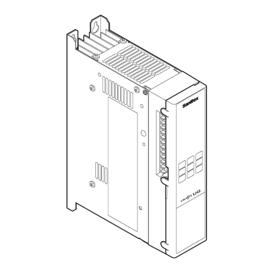
9.2 External View Models with a rated current of 25, 35, or 50 A Models with a rated current of 75 A... - Page 61 Models with a rated current of 100 A Models with a rated current of 150 A...
- Page 62 Models with a rated current of 250 A Models with a rated current of 350 or 450 A...
-
Page 63: Maintenance Parts
10 MAINTENANCE PARTS 10.1 Fuse Rated current of the unit Fuse model 25 A 660GH-050S 35 A 660GH-063S 50 A 660GH-100S 75 A 660GH-125S 100 A 660GH-160S 150 A 660GH-250S 250 A 660GH-350S 350 A 660GH-500S 450 A 660GH-710S Replacement procedure ※... -
Page 64: Conversion Board (Optional)
11 CONVERSION BOARD (OPTIONAL) The conversion board is an optional item that enables constant current control, constant voltage control, constant power control, heater disconnection detection, and other functions. This item does not come with the unit. Parts that are sold separately are required. 11.1 Before Use Checking the product... -
Page 65: How To Install The Conversion Board
*3: You must prepare the main circuit CT. The pattern selected here will be used repeatedly in explanations in the subsequent sections. Set the conversion board according to the corresponding pattern. (The pattern selected here is described as the “conversion board pattern” in the subsequent sections.) How to install the conversion board Install the conversion board by following its included installation manual. -
Page 66: Functions
Connections for patterns E, G, and I (The external CT and external PT are used.) ▲▲V External PT Load External CT (optional item) ■■A:5A 5A:0.1A Main circuit CT External CT Main circuit CT (prepared by user) 11.2 Functions Model list The available functions differ according to the conversion board model. -
Page 67: Feedback Control
Displays the powers detected with the built-in or external CT, external PT, Power ◎ and conversion board. Displays the powers detected with the external CT, external PT, and ● conversion board. ― Displays nothing. Feedback control This function performs feedback control using detected values. Mode can be set by display panel. - Page 68 F407: CT selection When conversion board pattern D, F, or H is selected, set this parameter to [1: Built-in CT]. Parameter F: Gradient (proportional) signal The adjustment method differs according to the conversion board pattern and the ratings of the load, external PT, and main circuit CT.
- Page 69 Adjustment method Feedback Conversion Maximum load Adjustment control board versus Rated value capacity method method pattern Maximum load Rated voltage of Constant B, G, H, I voltage the external PT voltage Maximum load Rated voltage of control < voltage the external PT Constant Maximum load Rated current of...
-
Page 70: Detection Value Adjustment Function
Adjustment method (1): When the maximum load capacity matches the rated value Use this function with the maximum gradient signal (100.0%). Adjustment method (2): When the maximum load capacity is smaller than the rated value * When the maximum load capacity can be output during adjustment Step 1: Minimize the gradient setting (0.0%) in advance to prevent a measured load value from exceeding the maximum load capacity at power ON. -
Page 71: Heater Disconnection Detection Function
Panel operation example: Correction to 50 A using F404 Step 5 Step 4 Step 3 Heater disconnection detection function Only the UG-TB3U and UG-TB3HU conversion boards are equipped with the heater disconnection detection function. There are two modes with different specifications. Standard version Highly functional version Simple... -
Page 72: Heater Disconnection Detection (Standard Version)
Standard version Highly functional version Detection 10% of the rated voltage and rated 30% of the rated current or higher range current or higher Number of Up to 20, the same material and Up to 10, the same material and heaters capacity capacity... -
Page 73: Setting Method
Connect the conversion board according to conversion board pattern I specified in “11.1.3 Connection diagrams.” There is no other connection specific to this function. The related parameters are shown below. F401: Heater disconnection detection function Select [2: Enable standard version] to enable the standard version function. When the function needs to be temporarily disabled for test operation or other purposes, select [0: Disable standard version]. -
Page 74: Heater Disconnection Detection (Highly Functional Version)
oP02: Heater resistance setting [oP02: Heater resistance setting] in OPTION mode of the display panel is used to record the initial heater resistance. Set it with the following procedure. Step 1: Complete the settings specified in the previous section. Step 2: Continue operation until the heater temperature becomes stable. -
Page 75: Connection Method
To use this function, the heaters, main circuit CT, external CT, and external PT need to be connected differently from the standard connection. Connect these items according to the following diagram. ▲▲V External PT Heater B ■■A:5A 5A:0.1A Heater A Main circuit CT External CT ※... - Page 76 Parameter U: Heater disconnection amount Set the threshold for the disconnection detection. The threshold needs to be set according to the number of heaters connected in parallel. Set the threshold with the following table as a reference. Number of heaters connected in parallel U: Heater disconnection amount (total of A and B) The above settings are approximate values.
-
Page 77: Characteristics
11.3 Characteristics Constant current control Specifications Condition Accuracy • Power supply voltage fluctuation Rated voltage ± 10% ±1% • Load Constant • Ambient temperature Constant • Power supply voltage Constant ±2% • Load fluctuation 10 times the rated load • Ambient temperature Constant •... -
Page 78: Constant Voltage Control
Constant voltage control Specifications Condition Accuracy • Power supply voltage fluctuation Rated voltage ± 10% ±1% • Load Constant • Ambient temperature Constant • Power supply voltage Constant ±1% • Load fluctuation 10 times the rated load • Ambient temperature Constant •... -
Page 79: Constant Power Control
Constant power control The following characteristics apply to UG-TB3, UG-TB3U, and UG-TB4. Specifications Condition Accuracy • Power supply voltage fluctuation Rated voltage ± 10% ±1% • Load Constant • Ambient temperature Constant • Power supply voltage Constant ±5% • Load fluctuation 4 times the rated load •... -
Page 80: Constant Power Control (Built-To-Order Products)
Constant power control (built-to-order products) The following characteristics apply to UG-TBH3, UG-TBH3U, and UG-TB4H. Specifications Condition Accuracy • Power supply voltage fluctuation Rated voltage ± 10% ±1% • Load Constant • Ambient temperature Constant • Power supply voltage Constant ±1% •... -
Page 81: External View
11.4 External View • External CT (optional item) Wiring terminals Primary side: M4 Secondary side: • External PT (optional item) • For 210 V and 110 V • For 440 V Wiring terminal processing: None (Process them according to your usage conditions.) -
Page 82: Maintenance And Inspection
12 MAINTENANCE AND INSPECTION Before maintenance and inspection, be sure to stop the supply of power to the main circuit and control circuit. Note that voltage is applied to the circuits even when operation is stopped via the ST terminal, panel, or communication. ... -
Page 83: Troubleshooting
13 TROUBLESHOOTING Symptom Item to check Action There is no Is an error code displayed? See “8 ERROR output. DETECTION” and remove the causes of the error. Is the ST terminal short-circuited with the Short-circuit them. PH terminal? Is the VF2 terminal open? Short-circuit it with the VE3 terminal. - Page 84 Symptom Item to check Action The detection Are the rated value settings correct? Review the [F0: Rated value display value] setting. does not match the measured value. Is the secondary-side rated current of the Review the [F0: Rated main circuit CT 5 A? value] setting in terms of the secondary-side rated current of 5 A.
-
Page 85: Unit Specifications
14 UNIT SPECIFICATIONS Item Specifications Model Without a fuse: UG1-2*** With a fuse: UG1-2***F, UG1-4***F (*** indicates the rated current.) Main circuit Number of phases Single Rated input voltage 100 V to 254 V, 380 V to 480 V Power supply ±10% fluctuation range Rated frequency... - Page 86 Item Specifications Control signal (1) Current signal: 4 to 20 mA (DC) (internal resistance: 250 Ω) (2) Voltage signal: 1 to 5 VDC, 0 to 5 VDC (internal resistance: 10 kΩ) Start/stop method Soft start/stop method, 0.5 seconds (default value) (Adjustable between 0.0 and 300 seconds) Cooling method Self cooling (for units with 75 A or less), air cooling (for units...
-
Page 87: Optional Item Specifications
15 OPTIONAL ITEM SPECIFICATIONS Item Specifications Conversion Constant current Power supply Rated voltage ± 10% ±5% FS board control voltage fluctuation characteristics Load 10 times the rated load ±5% FS (when the built-in Ambient –10°C to +50°C ±5% FS CT is used) temperature Constant current Power supply... - Page 88 Item Specifications Conversion Heater Load to apply Heaters with a constant resistance board disconnection Disconnection Output voltage and current that are detection detectable range 10% of the ratings or higher (standard Maximum number of version) parallel-connected loads Heater Load to apply Heaters with variable resistance disconnection detection (highly...
-
Page 89: Appendix A. Parameter List
APPENDIX A. PARAMETER LIST Changeable Display Default Name Setting range Increment Unit during symbol value operation Temperature to 100.0 ✓ control signal Manual (upper to 100.0 ✓ limit) signal Lower point (lower limit) to 100.0 ✓ signal Gradient 100.0 (proportional) to 100.0 ✓... - Page 90 Changeable Incre Default Code Function name Setting range Unit during ment value operation F000 Rated current setting 9999 ✓ F001 Rated voltage setting 999.9 ✓ 0: Phase control – – ✓ Waveform control F100 1: Intermittent cycle control method 2: Continuous cycle control 0: 4 to 20 mA (1 to 5 VDC) –...
- Page 91 Changeable Default Code Function name Setting range Increment Unit during value operation Selection of ✗ F300 target to change Default values of function characteristics Characteristic Characteristic Characteristic Characteristic Characteristic Characteristic Characteristic 0.0% of setting 10.0% of setting 20.0% of setting 30.0% of setting 40.0% of...
- Page 92 Changeable Incre Default Code Function name Setting range Unit during ment value operation 0: No feedback Feedback control 1: Constant current F400 method – – ✗ 2: Constant voltage 3: Constant power 0: Disable standard version Heater 1: Disable highly functional disconnection version F401...
- Page 93 Changeable Incre Default Code Function name Setting range Unit during ment value operation Er.01: Overcurrent F601 – – ✗ detection Er.02: F602 Temperature rise – – ✗ error F603 Er.03: Fuse blowout – – ✗ Er.04: Self-diagnosis F604 Load short circuit 0: No output –...
-
Page 94: Appendix B. Panel Transition Diagram
APPENDIX B. PANEL TRANSITION DIAGRAM... -
Page 95: Appendix C. Error Code List
APPENDIX C. ERROR CODE LIST Behavior Relay Recovery Code Function name after output Error history method detection destination Overcurrent detection Operation Power Relay (1) Saved Er.01 stops Temperature rise error Operation Power Relay (1) Saved Er.02 stops Fuse blowout Operation Power Relay (1) Saved... - Page 96 <MEMO>...
- Page 97 TEL+82-2-552-2803 FAX+82-2-552-8441 Taipei Branch (Taiwan) 8F-3, No. 46, Sec. 2, Zhongshan N. Rd., Zhongshan Dist., Taipei City 104016, Taiwan (R.O.C.) TEL+886-2-2543-5689 FAX+886-2-2536-7876 SANREX CORPORATION 50 Seaview Boulevard Port Washington, NY 11050-4618, U.S.A. TEL+1-516-625-1313 FAX+1-516-625-8845 https://www.sanrex.com/ https://sanrexwelding.com/ SANREX Block 5000, Ang Mo Kio Ave 5, #05-08 TechPlace II, Singapore 569870 ASIA PACIFIC PTE.LTD.