Table of Contents
Advertisement
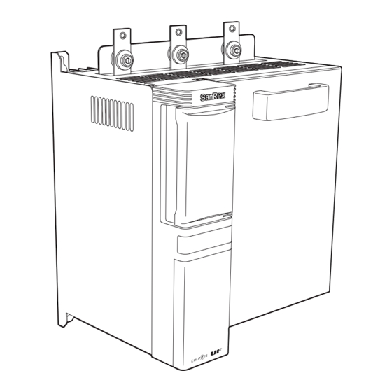
Thyristor Type Power Adjusting Unit
INSTRUCTION MANUAL
In order to operate this product properly, operators and other persons concerned are all requested to
read the "Safety Precautions" in this INSTRUCTION MANUAL thoroughly before using the product.
Strictly forward this INSTRUCTION MANUAL to the end users.
Advertisement
Table of Contents

Related Manuals for SanRex UF-3 Series


Summary of Contents for SanRex UF-3 Series
- Page 1 Thyristor Type Power Adjusting Unit INSTRUCTION MANUAL In order to operate this product properly, operators and other persons concerned are all requested to read the “Safety Precautions” in this INSTRUCTION MANUAL thoroughly before using the product. Strictly forward this INSTRUCTION MANUAL to the end users.
-
Page 2: Table Of Contents
TABLE OF CONTENTS FORWARD ........................1 SAFETY PRECAUTIONS..................2 Safety precautions to be observed by operators................. 2 Limitations for working environments ....................3 Precautions in installation ........................3 Precautions in wiring..........................4 Precautions in operation........................4 Precautions in maintenance and inspection..................5 PRECAUTIONS BEFORE USE ................6 Confirmation of the product ........................ -
Page 3: Forward
FORWARD Thank you very much for having purchased our “Thyristor Type Power Adjusting Unit UF3 Series”. The Thyristor Type Power Adjusting Unit has been widely used in various fields for its operability, reliability, or other superiorities. Our company consistently developed and manufactured the power adjusting unit starting from Thyristor ele- ments, and obtained user’s enjoyment and satisfaction on our various products. -
Page 4: Safety Precautions
SAFETY PRECAUTIONS Before installing, operating, maintaining, and inspecting this unit, be sure to read the present INSTRUCTION MANUAL and all other documents attached therein carefully in order for you to operate this unit properly. You and others concerned are requested to completely master all the know-how, safety instructions and precau- tions on the unit before use. -
Page 5: Limitations For Working Environments
Limitations for working environments CAUTION Absolutely do not operate nor store this unit in the following environments. Doing so may cause any failure in, damage to, or deterioration of the unit, resulting in fire. In hot, cold, or damp areas which are not in compliance with the requirements for ambient environ- ments specified in relevant catalogs and this INSTRUCTION MANUAL In area where exposed to direct sunlight In area where subjected to vibration or shock... -
Page 6: Precautions In Wiring
Precautions in wiring CAUTION Ask a specialist contractor for wiring work. Imperfect wiring work may cause electric shock or fire. Precautions to be taken by a specialist contractor DANGER Qualified specialists are required to turn off all the input power from a switch on the distribution panel and to make sure that power is off before connecting the input and output cables. -
Page 7: Precautions In Maintenance And Inspection
Precautions in maintenance and inspection PROHIBITED Persons other than approved persons (specialists) must not maintain, inspect, or repair this unit. Doing so may cause electric shock, injury, or fire. CAUTION To repair this unit or to replace defective parts, please contact the distributor of your purchase or any service company. -
Page 8: Precautions Before Use
PRECAUTIONS BEFORE USE Confirmation of the product Check the following items before installation. Check if correct products and optional items are provided as specified in the order. [Main body] Included items Q’ty UF3 unit body 1 unit Screws, nuts, and others for the connection of output wires a: Screw (25A-250A only) 6 pcs b: Bolt (350A and 450A only) -
Page 9: Connection Diagram Of Unit
CONNECTION DIAGRAM OF UNIT V E 1 VH 2 V L 2 V F 2 V E 3 For wiring of the external input terminals, refer to the Connection Diagram for Each Setting System. Use a transformer to obtain a 200/220V of the control power when other value of the power supply voltage is supplied for the main circuit. -
Page 10: External Connection Diagram Of Unit
EXTERNAL CONNECTION DIAGRAM OF UNIT Connection diagram for each setting system Connection diagrams for each setting system are shown below. Short circuit between GT and PH terminals during operation. Open-circuiting between them during operation forcibly stops output. Short-circuiting between ST and PH terminals starts output, and open-circuiting between them stops output. -
Page 11: How To Connect Unit Control Cables
How to connect unit control cables Use an easy lock to bind up the control cables (for control power supply, major failure output, minor fail- ure output, external input and output terminals, and conversion board) of the unit. Fix the easy locks on the unit. Bind the control cables with the easy locks. -
Page 12: How To Set Unit
HOW TO SET UNIT CAUTION Perform a setting of the unit with a good attention in that live parts are exposed when opening a cover of the unit. Before setting, turn off power. The standard initial setting of this unit is as listed below. If the unit is used under other conditions, open a cover on the lower part of the unit to change the setting of dip switch S1 located on the printed circuit. -
Page 13: Setting Of Dip Switch S3
Control system (S1-1) [Function] This makes a selection of phase control or cycle control. The phase control is to control the phase of half-cycle by means of its effective value. The cycle control is to control the number of turning ON in one cycle during a certain con- stant period by means of its effective value. -
Page 14: Function Characteristics
FUNCTION CHARACTERISTICS The standard unit has the linear characteristic between control signals and output level. It can be changed to have the following characteristics. Output voltage 100.0% 90.0% 80.0% 70.0% 60.0% 50.0% 40.0% 30.0% 20.0% 10.0% 0.0% 0.0% 20.0% 40.0% 60.0% 80.0% 100.0%... -
Page 15: Detection Of Abnormality
DETECTION OF ABNORMALITY Detection and indication of abnormality CAUTION In the event of any abnormality, check the Unit Abnormality lamp, stop operation of the unit, and then turn off power. When an abnormality detection circuit functions, an abnormality indication lamps lights up or flickers on the right-hand side of the terminal block inside the front panel of the unit. - Page 16 This detects fuse disconnection when a fuse built in the unit is disconnected. On detection of fuse dis- connection, an “F” indication lights up and operation stops. To resume operation, turn off the control power supply. The optional function is provided to detect heater disconnection. On detection of heater disconnection, an “HET”...
-
Page 17: Self-Diagnostic Function
Self-diagnostic function This function is provided somewhat differently depending on the combination with a conversion board (optional). Without conversion With conversion Operating status after board board detection of abnormality In running In stopping In running In stopping Thyristor open Available Operation stops. -
Page 18: External Warning Circuit
External warning circuit The abnormality detection circuit, when activates, causes an external warning relay in the unit to acti- vate. Major and minor failure relays are provided as the external warning relay. Major failure relay The abnormalities described below, when detected, forcibly stops operation and at the same time causes a major failure relay in the unit to activate. -
Page 19: External Dimensions Of Unit
EXTERNAL DIMENSIONS OF UNIT Model Rated Cooling External dimensions (mm) Weight Calorific Terminal current system (kg) value (W) screw Self-cooling 200 180 240 256 270 190 UF3-0025 Self-cooling 200 180 240 256 270 190 UF3-0035 Self-cooling 200 180 240 256 270 190 UF3-0050 Self-cooling 200 180 240 256 270 230 UF3-0075... -
Page 20: Fuse To Be Used
FUSE TO BE USED Unit current Fuse 200V/400V 660GH 50S-F 660GH 63S-F 660GH 100S-F 660GH 125S-F 100A 660GH 160S-F 150A 660GH 250S-F 250A 660GH 350S-F 350A 660GH 500S-F 450A 660GH 710S-F... -
Page 21: Others
OTHERS Precautions in use Use cables with sufficient capacity to the rated current of the unit, for wiring of the main circuit. For wiring of the main circuit, connect a R, S, T terminal to the power supply side, and an U, V, W terminal to the load side. -
Page 22: Maintenance And Inspection
Maintenance and inspection It is noted that dust, moisture, overheating, vibration, and others may degrade performance or cause any failure of the unit. Securely turn off the power for main and control circuits when conducting maintenance and inspec- tion. Keep in mind that any voltage is applied to the circuit even after the start/stop switch is set to stop. -
Page 23: Display Panel (Model Uf-Dp)
OPTION Display panel (Model UF-DP) Functions Using a display panel provides the following functions. Read the “INSTRUCTION MANUAL for Display Panel” for details. Can display output current, voltage, and The functional feature allows the selec- power for checking. tion of seven types of input/output char- acteristics in addition to linear type. -
Page 24: Unit Specifications
UNIT SPECIFICATIONS Description Specifications Models 3-arm : UF3-0 6-arm : UF3-0 Main Phase Three phase circuit Rated input voltage 100/110/120V , 200/220/254V , 380/400/440/460/480V Fluctuation range of ±10% power supply Rated frequency 50/60Hz (automatic judgment system of frequency) Rated current 25A, 35A, 50A, 75A, 100A, 150A, 250A, 350A, 450A (at ambient (600A, 800A, 1200A Semi-standard) - Page 25 -MEMO-...
- Page 26 533-0031,Japan Singapore Tel: 06-6325-0500 Fax: 06-6321-0355 Tel: +65-6457-8867,+65-6459-6426 Fax: +65-6459-6425 http://www.sansha.co.jp/ FOSHAN CITY SHUNDE SANREX LIMITED (China) SANREX CORPORATION (U.S.A) Dazhou Shiliang Road Lunjiao Town, Shunde District, Foshan City, Guandong Province 528308 P.R.China 50Seaview Boulevard Port Washington,NY 11050-4618, Tel: +86-757-2733-3688 Fax: +86-757-2783-3547 U.S.A...
Need help?
Do you have a question about the UF-3 Series and is the answer not in the manual?
Questions and answers