
Related Manuals for Coast to Coast PRIZE CUBE


Summary of Contents for Coast to Coast PRIZE CUBE
- Page 1 USER USER MANUAL MANUAL 804MAN001 service@coastentertainment.com P: 561.588.5200 | Fax: 561.493.2999 2201 4th Avenue N, Lake Worth Beach,FL 33461...
-
Page 2: Table Of Contents
Table of Contents Game Dimensions .................... Pg. 3 Setting Up Your Cube ..................Pg. 4-7 Menu Options ....................Pg. 8-10 Audit Menu ...................... Pg. 11 Error Codes ....................Pg. 12-13 Connection Overview ..................Pg. 14 Wiring Diagram....................Pg. 15... -
Page 3: Game Dimensions
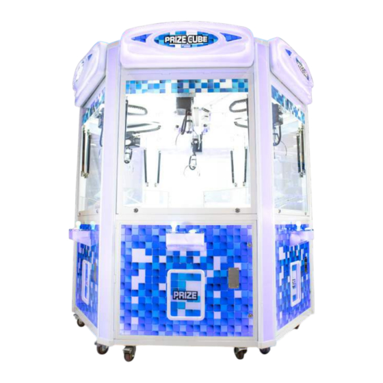
Game Dimensions 98 in 2489 mm 89 in 2260 mm 102 in 2591 mm Game Dimensions Installed 102 in (2591mm) x 89 in (2260 mm) x 98 in (2489 mm) 1645lbs/746kg Palleted 85 in (2159 mm) L x 85 in (2159 mm) W x 94 in (2388 mm) H 1,660lbs/753kg... -
Page 4: Setting Up Your Cube
Setting Up Your Prize Cube 1. There shall be another piece of small plate which is packed separately with the machine. Inside the machine there shall be 2 pieces of big half round plate, 2 aluminum sticks and 1 motor. - Page 5 3. Put the small plate inside then mount motor as shown. 4. Plug in the 2 connectors (Main Power and Motor) as depicted below. 5. Pull LED ligh connector through the roof 6. Mount the wood boards to the top...
- Page 6 7. Plug in the LED connector into the metal housing 8. Mount the metal housing onto the top wood 9. Install the half round art plate...
- Page 7 10. Using the 2 metal plates to sandwich the acrylic peices and cover the seem. 11. Slide the aluminum cover into each joint 12. Install the corner caps.
-
Page 8: Menu Options
Menu Options To enter the crane settings window press and hold the for aproximately 2 seconds. The front console display should come up with the below options. Navigate the option using the menu option with K1 and K2, to select a menu option use K0, and to go back or exit menus use K3. - Page 9 Menu Options 4. Claw Strength 4. Claw Strength Max - 1-48V Grabbing power, better not lower than 30V. Default set to 35V Min - 1-24V Retaining power, can set automatically at the lasxt section. Default set to 15V Change time Change time - 0.0 - 10s Holding time in between grabbing power and retaining power, voltage will be dropping smoothly Auto detect...
- Page 10 Menu Options 15. Bonus Coin 15. Bonus Coin Yes / No Yes / No Bonus Credit setting 16. Winner Show O昀昀 16. Winner Show O昀昀 Yes / No Yes / No Winner game not winning function On or O昀昀 1 Chance 1 Chance Winner game not winning extra free game All Show O昀昀 / Half Show O昀昀 All Show O昀昀 / Half Show O昀昀 Winner game e昀昀ects show up randomly 17.
-
Page 11: Audit Menu
Audit Menu Press to enter Audit menus options, once in press as prompted on screen to leave. 1. Total Income Total of credits inserted into machine 2. Current Income Total credits insterted since last cleared 3. Coin 1 Income Total income on Coin 1 since last cleared 4. -
Page 12: Error Codes
Error Codes Error codes will show at the bo琀琀om of the display at all 琀椀mes. Error Code Error Code Fixes Fixes Coin 1 Error 1. Check the mechanism if it is broken 2. Check the coin stuck Coin mech set in “No” mode 1. Reset machine to default setting by turning the game o昀昀 then pressing K0 + K3 Memory Error and powering back on... - Page 13 Error Codes Error Code Error Code Fixes Fixes Upper Sw error Claw Up Stop Switch Error 1. Check for loose cable at switch. 2. Make sure switch is wired properlly (Signal line to NO) 3. Replace Switch Down Sw error Claw Down Stop Switch Error 1.
-
Page 14: Connection Overview
Connection Overview Notes: 1. Make sure the opposite wall from the sensor has the black aphotic paint sticker, or the sensor will not work properly. If the following errors persist contact our customer service. A. Red light always on or blinking B. -
Page 15: Wiring Diagram
Wiring Diagrams Connector Connector Usage Usage Color Color Connector Connector Usage Usage Color Color Yello Blue Blue Green Black Yellow Power Supply Green LCD Display Orange Brown Black Black Brown White Voltage Meter Speakers Black Gray Connector J3 o stage one board... - Page 16 2201 4th Ave N. Lake Worth Beach, FL 33461 www.coasttocoastcranes.com 1-800-224-1717...
Need help?
Do you have a question about the PRIZE CUBE and is the answer not in the manual?
Questions and answers