Table of Contents
Advertisement
Advertisement
Table of Contents

Related Manuals for Coast to Coast TICKET Zone


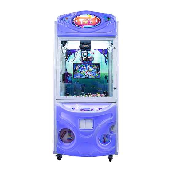
Summary of Contents for Coast to Coast TICKET Zone
- Page 1 March 2020...
-
Page 2: Table Of Contents
Table of Contents Main Components ............................3 Game Set Up ............................... 4 Assembly/Unpacking ..........................4 Mounting the header ..........................5 RFID Box: ..............................7 Game Behavior ............................. 10 Game Payout and adjustments ......................11 Programming Options: ..........................12 Programming Tree ..........................13 Programing Options Explained ...................... -
Page 3: Main Components
Main Components... -
Page 4: Game Set Up
Game Set Up Assembly/Unpacking Be sure that all packing material is cleared, and the game is sturdy on the ground. Inside the playfield is a box with the header of the game. Header The claw is restrained by 5 zip ties. Cut them carefully before starting game. -
Page 5: Mounting The Header
Mounting the header Feed wires through the two holes and connect to existing harness. Header Back View Be sure to align lower brackets with the two designated holes. - Page 6 Once those are aligned use the 4 screws and washers provided with the header to secure it in place. Game Top View...
-
Page 7: Rfid Box
RFID Box: Setting in your new RFID Box. Be sure the following connections are installed properly. Ground wire to RFID controller board P6. Attach the end of the ground wire to door. Be sure to route into harness to keep it from getting pinched. - Page 8 From the RFID box there will also be a yellow and black harness that comes from the Red and Black LED Strip that will need to be plugged in. If the four pin that is currently plugged in is still plugged in unplug it and replace it with the 4-pin coming from the new RFID Box.
- Page 9 From RFID Box there is a 6-pin connector with one black wire and a 6-pin connector with 5 colored wires. The black connector plugs into J22 all the way to the edge with the wire towards the center. The second plug is placed on J17. Be sure that there is nothing plugged into J8 as that is only used for programming the board.
- Page 10 LED Lights: This relay allows for power to reach the LEDs inside the cabinet of the game.
-
Page 11: Game Behavior
Drops the claw before returning to it up right place. “Enter the Ticket Zone” is played and the white LEDs inside the cabinet turn on. Note: If the game fails to boot the white cabinet LEDs will not turn on. -
Page 12: Programming Options
Programming Options: Using the Stage 1 hand controller you can get into the programing options of your crane machine. Dial Display Screen Press the Dial in to enter the Menu Mode. Moving the Dial clockwise will move through the option. Counterclockwise goes back to the previous option on your Display Screen. -
Page 13: Programming Tree
Programming Tree Exit Counters Life Time $ Plays Tickets Save and Exit Coin in 1 Game Counters Coin in 2 $ per play $.25 - $15 Ticket Value $.25 - $600 Reset Counters Reset Config Exit Menu Timer Display 0 - 99 Left Right Forward... - Page 14 Programming Tree Continued… Exit Game set up Pulse x Credit 1 - 80 Game Length 1 - 99 Seconds Up Limit Disabled Yes/No Low Limit Yes/No Disabled Claw Strength 0 - 100 Up Speed 1 - 100 (Homing) Left/ Right Speed Game Config 1 - 100 (In Play)
-
Page 15: Programing Options Explained
Programing Options Explained 1) Save Configuration & Play (Save any setting that were changed and start game mode) 2) Game Counters a. Exit Counters b. Lifetime $ (it displays the amount of $ earned by the machine) c. Number of Plays (The amount of games played) d. - Page 16 4) Game Configuration a. Exit Game Setup b. Pulse per credit i. From 1 to 80 c. Game Length (in seconds) i. 1 to 99 d. UP Limit Disable i. Yes/No e. Low Limit Disable i. Yes/No Claw Grab Strength (% of 48Volts) i.
-
Page 17: Error Codes And Troubleshooting
Error Codes and Troubleshooting Error Code Description Out of Service 1 Communication to DLP Radio Board 2 Internal DLP Module Error 3 Out of Tickets 4 Bucket Door Error E1: Communication to DLP Board Troubleshooting: Check Ground wire is plugged in on board properly. Check Harnessing down to the Timer Board. -
Page 18: Components
Components RFID Stage One Controller Part Number: 7100BRD024 Location: Inside lower cabinet on the top right drawer. I.D. Switch Setting: All Off (00000000) Radio Control Board Part Number: 7100BRD029 Location: On the top of the RFID Box I.D. Switch Setting: N/A This controls the RFID’s actions 4 Digit Timer Display Part Number: 7100BRD060... - Page 19 RFID Antenna Board Part Number: TBA Location: Inside Top RFID box assembly I.D. Switch Setting: N/A This is the RFID Antenna that connect to the radio board. RGB Light controller board Part Number: TBA Location: Inside front door panel. I.D. Switch Settings: 0000 (all off if only using one crane) This board links multiple cranes’...
Need help?
Do you have a question about the TICKET Zone and is the answer not in the manual?
Questions and answers