
Related Manuals for United CoolAir PAC12G3ASC Series


Summary of Contents for United CoolAir PAC12G3ASC Series
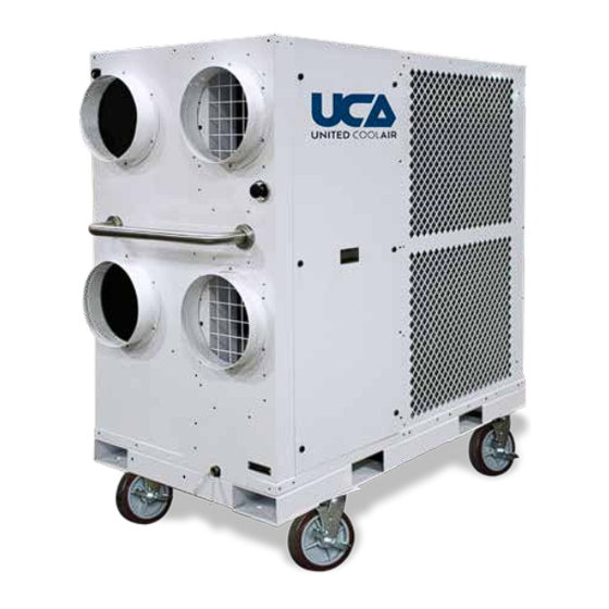
- Page 1 INSTALLATION AND OPERATION MANUAL 12-TON PORTABLE AIR CONDITIONING UNIT Serial Number ����������������������������...
-
Page 2: Identification Of Your Unit
MIN. CLEARANCE TO COMBUSTIBLE SURFACES - 0 IN 9CA-6242 IDENTIFICATION OF YOUR UNIT The Data Tag contains important information on how identify your United CoolAir Unit. See Figure 1 for more information on locating tag. Subject to change without notice. -
Page 3: Table Of Contents
Table of Contents IDENTIFICATION OF YOUR UNIT . . . . . . . . . . . . . . . . . . . . . . . . . . . . . . . . . . . . . . . . . . . . . . . . . . . . . . . . . . . 2 PAC12G3ASC* (208/230 Volt) –... -
Page 4: Pac12G3Asc* (208/230 Volt) - Product Specifications
PAC12G3ASC* (208/230 Volt) – PRODUCT SPECIFICATIONS COOLING MODE Design Indoor Dry Bulb / Wet Bulb 80°F / 67°F Design Outdoor Ambient Temperature 95°F Total Cooling Capacity BTU/HR 144,000 Sensible Cooling Capacity 104,400 Minimum Indoor Ambient Temperature 68°F Design Return Air Dry Bulb 80°F Design Return Air Relative Humidity POWER REQUIREMENTS... -
Page 5: Pac12G4Asc* (460 Volt) - Product Specifications
PAC12G4ASC* (460 Volt) – PRODUCT SPECIFICATIONS COOLING MODE Design Indoor Dry Bulb / Wet Bulb 80°F / 67°F Design Outdoor Ambient Temperature 95°F Total Cooling Capacity BTU/HR 144,000 Sensible Cooling Capacity 104,400 Minimum Indoor Ambient Temperature 68°F Design Return Air Dry Bulb 80°F Design Return Air Relative Humidity POWER REQUIREMENTS... -
Page 6: General Information
GENERAL INFORMATION The PAC12GxAS is a portable air conditioning unit designed for air conditioning of spaces such as tents, construction sites and remote buildings. This product may also have optional electric heaters. If supplied with the electric heat option, refer to the specifications and operating sections Data provided for the electric heaters. -
Page 7: Unit Setup
UNIT SETUP to the electrical wiring diagram for Main Power connections also shown in Figure 4 – Camlock Power Connections which are located directly Location and Clearances below the control panel. Select a location that permits unobstructed airflow into the condenser coil and away from the condenser fan discharge air outlets. -
Page 8: Duct Connections
power source . The second function is to use the (h) For 208 – 230 volt applications, if the measured voltage to select the control circuit type displayed voltage is greater than 190 VAC 208 or 230 volt. Selecting the type of voltage for and less than 219 volts AC, set the Control the control circuit based the measured voltage Voltage Selector Switch (CVSS) to the 208... -
Page 9: Condensate Drain
3. Terminate the ends of each duct to the space being conditioned making sure that supply air 2. Drain to an optional condensate pump, to pump does not have the possibility of short cycling condensate to another location. Refer to the back into the return air. - Page 10 energize to start the Evaporator Motor (ME). The the thermostats temperature measuring bulb, the Evaporator Fan will operate continuously in the compressor contactor (CCR) will energize the Fan and Cool modes of operation. It will also Compressor (CR) and the Amber Cool Indicator operate continuously during optional Heat Mode.
- Page 11 To stop the unit, turn Selector Switch (SS) to the press the ON/OFF button again and OFF OFF position. will appear on the LCD. NOTE: There is a manual damper slide damper at (b) Press the (+) or (–) sign and the Digits on the top of the condenser blower discharge the LCD will flash.
-
Page 12: Unit Safety Devices
Thermostat Bypass may have tripped on high refrigerant pressure. Disconnect power using the unit’s circuit breaker. The unit also has a Thermostat Bypass Switch Remove the Access Panel to the Compressor which is used to manually force cooling or heating Compartment and locate the Manual Reset High to be energized based on the mode selected by Pressure Switch. -
Page 13: Unit Components
UNIT COMPONENTS power connection block on the PAC12 unit will correct the phasing to the unit. The Green Power Lamp will illuminate whether the phase sequence Electrical Components is correct or not for reference that the system has power applied. Contactors Thermostat Contactors are used to energize the evaporator... - Page 14 low pressure, low temperature refrigerant vapor refrigerant discharge pressure starts to fall below entering the suction side of the compressor into 290 psig, the valve mechanically modulates open a high pressure, high temperature gas at the to bypass some of the discharge gas around the discharge side of the compressor.
-
Page 15: Routine Maintenance
Thermostatic Expansion Valve Motor and Drive Components The expansion valve regulates the amount of Grease fittings are provided directly on the pillow liquid refrigerant entering into the evaporator. As block bearings for both the evaporator blower the liquid enters into the expansion valve, the assembly and the condenser blower assembly. - Page 16 Frequency of Lubrication Frequency of Lubrication depends on operating conditions. The following chart gives the frequency of lubrication based upon operational duty and should be used as a guide for determining when bearings should be lubricated. Duty Grease Interval Low Usage 12 months A grease fitting is Periodic...
- Page 17 slip causing loss of blower speed, the belts will Check the sheave alignment to make sure that glaze due to excessive slipping and heat leading the sheave faces are in the same plane. Check to premature belt failure. Belts may slip during this by placing a straight edge across the face start-up, but slipping should stop as soon as of the sheaves.
-
Page 18: Troubleshooting Guide
TROUBLESHOOTING GUIDE WARNING: BE AWARE OF HIGH POWER SITUATIONS WHILE TROUBLESHOOTING. THERE ARE ALSO MOVING BELTS, BLOWERS, AND MOTORS WHILE POWER IS CONNECTED TO THE UNIT. WHEN REACHING INTO ANY OF THE UNIT SECTIONS TO MAKE ADJUSTMENTS TO THE UNIT. PLEASE DISCONNECT POWER FROM THE UNIT. Problem Cause Description... - Page 19 Supply and return air grills in space are Re-locate objects in front of air grills or re-locate restricted. supply and return air grills in space. Dirty return air filter. Clean or replace air filter. Low-pressure switch open and does not reset. Replace low-pressure switch.
Need help?
Do you have a question about the PAC12G3ASC Series and is the answer not in the manual?
Questions and answers