Advertisement
Quick Links
©2023 Stillwater Designs
19417164-20231006
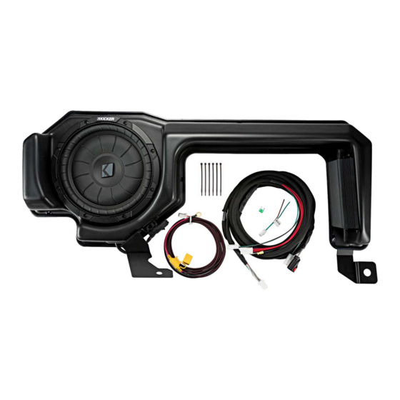
Subwoofer Assembly
Subwoofer Power Harness
Wire Ties
19417164
Designed for 2019 and newer
Chevrolet® Silverado/GMC®
Sierra 1500 as well as 2020
and newer 2500/3500 Crew
Cab or Double Cab trucks.
Subwoofer Harness
Fuse
Adaptor Harness
1
Advertisement

Related Manuals for Kicker 19417164


Summary of Contents for Kicker 19417164
- Page 1 19417164 Designed for 2019 and newer Chevrolet® Silverado/GMC® Sierra 1500 as well as 2020 and newer 2500/3500 Crew Cab or Double Cab trucks. Subwoofer Assembly Subwoofer Power Harness Subwoofer Harness Wire Ties Fuse Adaptor Harness ©2023 Stillwater Designs 19417164-20231006 ...
- Page 2 1. Disconnect negative battery cable. 2. Remove the cover of the battery junction box. Fig. 1 3. Make sure supplied fuse is not installed in fuse holder and connect the subwoofer power wire to the stud pictured in figure 2. Torque to 4.7Nm (42in-lb) Connect one power harness to each terminal...
- Page 3 2024 and newer Trucks NOTE: The newer style grommet requires using a fish tape or some type of stiff wire to penetrate the grommet. There is a provision in the grommet to allow the power harness to pass through the grommet. DO NOT TRY TO PENETRATE THE GROMMET ANY OTHER WAY THAN DESCRIBED.
- Page 4 8. Install the white three pin power connector on the subwoofer power wire. Close the retainer. Fig. 7 9. Connect the subwoofer power wire to the subwoofer harness. Fig. 8 Then close retainer ...
- Page 5 Trucks without Bose® audio system 1. Locate the audio control module next to the glove compartment and disconnect the two 28 pin connectors. Fig. 12 2. Find the connector with the solid blue and brown/blue stripe wires and peal back the cloth sheathing.
- Page 6 14. Remove the two 10mm nuts securing the jack bracket. Fig. 15 15. Remove the jack tool bag. NOTE: If equipped with the optional carpeted storage tray as pictured in Fig. 12, remove at this time. The storage tray cannot be used in conjunction with the subwoofer.
- Page 7 18. Route subwoofer harness from passenger’s side to driver’s side under carpet. Subwoofer harness should be routed behind seat brackets. Routing from one precut opening to the next will aid in harness routing. Fig. 18 ...
- Page 8 22. Reinstall seat bolt. Torque to 109Nm (80ft/lb) 23. Reinstall all previously removed parts in reverse order. 24. Install supplied fuses into fuse holders. 25. Reconnect negative battery cable. Tighten to 7.5Nm (66in-lb) ...
- Page 9 Splicing T echnique Splicing Copper Wire Using Splice Sleeves. Special Tools: • EL-38125-10 Splice Sleeve Crimping Tool • J-38125-5A Ultra Torch Special Tool • J-38125-8 Splice Sleeve Crimping Tool Note: The DuraSeal splice sleeves have the following 2 critical features: •...
- Page 10 Strip the insulation: • When adding a length of wire to the existing harness, use the same size wire as the original wire. • Perform one of the following items in order to find the correct wire size: Find the wire on the schematic and convert to regional wiring gauge size. If you are unsure of the wire size, begin with the largest opening in the wire stripper and work down until achieving a clean strip of the insulation.
- Page 11 The J-38125-8 splice sleeve crimping tool has three crimp nests. The largest crimp nest (3) is used for crimping 10 and 12 gauge wires. The second largest crimp nest (2) is used for crimping 14 and 16 gauge wires. The smallest crimp nest (1) is used for crimping 18 to 20 gauge wires.
- Page 12 Troubleshooting the Kicker Integrated Systems If you experience a problem once the subwoofer or amplifier are installed use this guide to locate the trouble. The radio is working, but the Subwoofer is not working: Check the battery voltage to make sure it is not discharged below 11 volts.
- Page 13 If you continue to experience problems after troubleshooting, please contact KICKER Technical Support at 405-533-7499 oesupport@kicker.com P.O. Box 459 • Stillwater, Oklahoma 74076 • USA • (405) 624–8510 ...
Need help?
Do you have a question about the 19417164 and is the answer not in the manual?
Questions and answers