Advertisement
BOGEN
COMMUNICATIONS, INC.
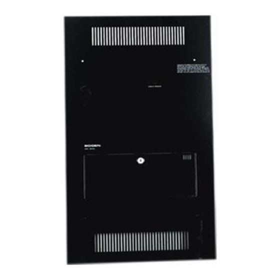
WALL MOUNT MODULAR AMPLIFIERS
WMA-80 & WMA-160
INSTALLATION AND OPERATION
INSTRUCTIONS
The Bogen WMA-80* and WMA-160 are professional quality
wall-mounting amplifiers suited for use in gymnasiums, auditori¬
ums, and banquet rooms where inconspicuous, permanent mount¬
ing is desired. Both models combine modular flexibility with power
MOSFET performance and are available in flush-mount or sur¬
face-mount configurations. A locking panel on the front cover
secures the unit when not in use, and is designed so that it cannot
be removed without access to the area behind the panel.
The WMA-80 and WMA-160 arc ralcd at 80 ami 160 walls,
respectively. Each has 8 input channels: a built-in Lo-Z mic¬
rophone input (with a 3-pin female connector); a Hi-Z Projector
input (with 1/4" connector); and six module ports. The ports accept
any combination of the Bogen D-Series plug-in modules to define
the function of each channel.
Inputs are mixed on an active buss, allowing interaction for
three levels of priority Modules set to priority level 1 are muted
by modules set to priority levels 2 or 3. Modules set to priority level
2 mute modules set to level 1 and are muted by modules set to
priority level 3.
To obtain the best control over room acoustics, the WMA
Series features a 10-band graphic equalizer, which provides ±8dB
at ISO centers of 125,200,315, 500,800,1.2k, 2k, 3.1k, 5k, and 8k
Hz. Equalizer slide controls are located behind the front cover to
prevent tampering after installation and setup. A low-cut filter
(-3dB @ 65Hz) and tone control bypass switch are also provided
and are located in the module port cage.
Individual level controls are provided for each channel. A
Master Volume Control sets the final output level. A bar-graph-
type LED output meter provides output level indication.
Power MOSFET output stages and protective circuitry provide
performance and reliability and eliminate the need for output fuses
and thermal fuse links. A built-in compressor circuit protects
speakers/drivers from damage by limiting the output of the pream¬
plifier to 1 volt.
Each amplifier has a direct 4-ohm output for use in professional
applications plus transformer-coupled 8-ohm and 25V and 70V
outputs. The amplifiers operate from a 120 volt, 60Hz AC source.
A push-to-rescl circuit breaker is included.
UNPACKING
The amplifier was carefully checked before leaving the factory.
Inspect the shipping container and components for evidence of
improper handling. If the unit has been damaged, place an imme¬
diate claim with the dealer/distributor from whom the unit was
purchased. If the unit was shipped directly to you, notify the
transportation carrier without delay and file a claim.
INSTALLATION
CAUTION
These installation instructions are for use by qualified
personnel only. To avoid an elertrio shook, do not perform
any installation or service procedures other than that con¬
tained in the Operating Instructions unless you are
qualified to do so. Refer all servicing to qualified service
pzmmneL
BACK BOX INSTALLATION
A surface-mount or flush-mount cabinet is required for instal¬
lation. Follow the instructions on page 2 of this manual to install
the surface mount (BB-S) or flush-mount (BB-F) enclosure.
OUTPUT CONNECTIONS, LOW-CUT, EQ DEFEAT
The amplifiers provide a direct output at 4-ohms and trans¬
former-coupled 8-ohm, 25V and 70V taps for use with distributed
systems. The WMA-80 includes a 25V center-tapped output.
When using transformer-coupled taps, be sure that the link on
the output terminal strip connects the OUTPUT TRANSFORMER
IN terminal to the DIRECT + terminal. Remove the link when
using the direct output
A Low-Cut filter switch, located in the port cage, reduces
low-frequencies when using transformer-coupled outputs. Set the
switch to IN when using transformer-coupled outputs, and OUT
when using the direct output.
The Tone Control defeat switch, located in the port cage,
bypasses the amplifier's equalizer filter controls for a flat response.
Set the switch to IN to enable the equalization filters and OUT to
bypass the filters.
MODULE INSTALLATION
Before installing each module, follow the instructions on page
3 of this manual to configure it for the desired function or priority
level. Set the HIGH-/LOW-CUT filter controls and GAIN con¬
trols on modules so equipped to mid-rotation.
To prevent damage to the modules or the amplifier, be sure
that the amplifier POWER switch Is in the OFF position before
installing or removing modules. To install modules, align the top
and bottom edges of the module printed circuit board in the slots
of the port, and slide into the port to engage the edge connectors.
Secure the module with two screws.
ModiHes set to priority level 1 receive (and are muted by)
priority signals from any module set to priority level2 or 3. Modules
set to priority level 2 send priority signals to mute any modules set
to priority level 1, and receive priority signals from any module set
to priority level 3. Modules set to priority level 3 send priority
signals to mute modules set to priority level 1 or 2.
•WMA-80 is UL listed.
Printed In Korsa
9008
94-5887-03
Advertisement
Table of Contents


Need help?
Do you have a question about the WMA-80 and is the answer not in the manual?
Questions and answers