Table of Contents
Advertisement
Available languages
Available languages
Quick Links
HARBOR BREEZE and logo design are
trademarks or registered trademarks of
LF, LLC. All rights reserved.
Purchase Date
Questions, problems, missing parts? Before returning to your retailer, call our customer
service department at 1-888-251-1003, 8 a.m. - 8 p.m., EST, Monday - Sunday. You could
also contact us at partsplus@lowes.com.
AS21781
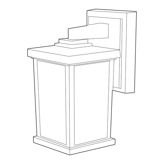
WALL LANTERN
1
ITEM #2062005
2602006
MODEL #WL131MBK
WL131WW
Español p. 11
ATTACH YOUR RECEIPT HERE
ADJUNTE SU RECIBO AQUÍ
For Wet
Location
E87731
Advertisement
Chapters
Table of Contents

Related Manuals for Harbor Breeze WL131MBK


Summary of Contents for Harbor Breeze WL131MBK
- Page 1 ITEM #2062005 2602006 WALL LANTERN MODEL #WL131MBK WL131WW HARBOR BREEZE and logo design are trademarks or registered trademarks of Español p. 11 LF, LLC. All rights reserved. ATTACH YOUR RECEIPT HERE ADJUNTE SU RECIBO AQUÍ For Wet Location Purchase Date...
-
Page 2: Table Of Contents
TABLE OF CONTENTS Package Contents ....................... 2 Hardware Contents ......................3 Safety Information ........................ 3 Preparation .......................... 5 Assembly Instructions ......................5 Care and Maintenance ....................... 10 Troubleshooting........................10 Warranty ..........................10 PACKAGE CONTENTS PART DESCRIPTION QUANTITY Fixture... -
Page 3: Hardware Contents
HARDWARE CONTENTS (shown actual size) Wire Connector Qty. 3 Fixture Screw Qty. 2 Mounting Decorative Plate (preassembled) Qty. 1 Qty. 2 Qty. 2 SAFETY INFORMATION READ AND SAVE THESE INSTRUCTIONS. DANGER • For your protection and safety, carefully read and understand the information provided in this manual completely before attempting to assemble, install or operate this product. - Page 4 SAFETY INFORMATION DANGER • DO NOT connect the bare or green insulation fixture ground wire to the black (HOT) current-carrying wire or the white (NEUTRAL) house wire. Connection of the bare or green fixture ground wire to the black or white house wires may cause metal parts of the fixture to carry electrical currents.
-
Page 5: Preparation
PREPARATION Before beginning assembly of product, make sure all parts are present. Compare parts with package contents list and hardware contents list. If any part is missing or damaged, do not attempt to install, operate or assemble the product. Estimated Assembly Time: 30 minutes Tools Required for Assembly (not included): Flathead Screwdriver, Phillips Screwdriver, Wire Strippers, Pliers, Wire Cutters, Safety Glasses, Stepladder, Electrical Tape, Silicone Weather Sealant (and tool to apply sealant) - Page 6 ASSEMBLY INSTRUCTIONS Remove preassembled nut (EE) from each fixture screw (CC). Insert fixture screws (CC) completely into mounting plate (AA), one directly across from the other. Reattach one nut (EE) to each fixture screw (CC). [Adjustment will be made later.] Hardware Used Mounting Plate [not shown actual size]...
- Page 7 ASSEMBLY INSTRUCTIONS Temporarily place fixture (A) over mounting plate Outlet Box (AA) to determine amount of adjustment necessary for fixture screws (CC). NOTE: Fixture screws (CC) should come through holes in fixture (A) just enough so decorative nuts (DD) fit flush against fixture (A) when mounted.
- Page 8 ASSEMBLY INSTRUCTIONS 6b. Connect BARE/GREEN ground wire from outlet WHITE box to BARE wire from fixture (A) using wire BLACK connector (BB). Connect WHITE wire from fixture (A) to WHITE wire from outlet box using wire connector (BB). Connect BLACK wire from fixture (A) to BLACK wire from outlet box using wire connector (BB).
- Page 9 ASSEMBLY INSTRUCTIONS 8. Align holes in fixture (A) with fixture screws (CC) on mounting plate (AA) and push fixture (A) toward wall. Attach fixture (A) to mounting plate (AA) using the decorative nuts (DD). Hardware Used Mounting Plate [not shown actual size] Fixture Screw Decorative Nut 9.
-
Page 10: Care And Maintenance
ASSEMBLY INSTRUCTIONS 11. After completing installation, caulk mounting surface of fixture (A) with silicone weather sealant (not included). WARNING: Failure to caulk fixture mounting surface with silicone weather sealant may result in water damage in outlet box, which may cause electrical malfunction or electrical shock. CARE AND MAINTENANCE Shut off main power supply. - Page 11 ARTÍCULO #2062005 2602006 FAROL DE PARED MODELO #WL131MBK WL131WW HARBOR BREEZE y el diseño del logotipo son marcas comerciales o marcas registradas de LF, LLC. Todos los derechos reservados. For Wet Location E87731 APROBADO PARA UTILIZARSE Fecha de compra EN LUGARES MOJADOS ¿Preguntas, problemas, piezas faltantes? Antes de volver a la tienda, llame a nuestro...
-
Page 12: Contenido Del Paquete
ÍNDICE Contenido del paquete ....................... 12 Aditamentos ..........................13 Información de seguridad ......................13 Preparación ..........................15 Instrucciones de ensamblaje ..................... 15 Cuidado y mantenimiento ......................20 Solución de problemas ......................20 Garantía ............................ 20 CONTENIDO DEL PAQUETE PIEZA DESCRIPCIÓN CANTIDAD Lámpara... -
Page 13: Aditamentos
ADITAMENTOS (se muestran en tamaño real) Conector de cables Cant. 3 Tornillo de la lámpara Cant. 2 Placa de Tuerca Tuerca (preensamblada) montaje decorativa Cant. 1 Cant. 2 Cant. 2 INFORMACIÓN DE SEGURIDAD LEA Y GUARDE ESTAS INSTRUCCIONES. PELIGRO • Por su propia protección y seguridad, lea atentamente y comprenda la información de este manual en su totalidad antes de intentar ensamblar, instalar o usar este producto. - Page 14 INFORMACIÓN DE SEGURIDAD PELIGRO • NO conecte el conductor de puesta a tierra de aislamiento desnudo o verde de la lámpara al conductor negro (DE CORRIENTE) que lleva la corriente o al conductor blanco (NEUTRO) de la casa. Conectar el conductor de tierra desnudo o verde de la lámpara al conductor negro o blanco de la casa puede provocar que las piezas metálicas de la lámpara conduzcan corriente eléctrica.
-
Page 15: Preparación
PREPARACIÓN Antes de comenzar a ensamblar el producto, asegúrese de tener todas las piezas. Compare las piezas con la lista del contenido del paquete y la lista de los aditamentos. No intente instalar, utilizar o ensamblar el producto si falta alguna pieza o si alguna está dañada. Tiempo estimado de ensamblaje: 30 minutos Herramientas necesarias para el ensamblaje (no se incluyen): destornillador de cabeza plana, destornillador Phillips, pinzas pelacables, pinzas, pinzas cortacables, gafas de seguridad, escalera... - Page 16 INSTRUCCIONES DE ENSAMBLAJE Quite la tuerca (EE) preensamblada de cada tornillo de la lámpara (CC). Atornille los tornillos de la lámpara (CC) por completo en la placa de montaje (AA), uno directamente enfrente del otro. Vuelva a fijar una tuerca (EE) a cada tornillo de la lámpara (CC). [Se harán los ajustes más adelante.] Aditamentos utilizados Placa de montaje...
- Page 17 INSTRUCCIONES DE ENSAMBLAJE Coloque temporalmente la lámpara (A) sobre la Caja de salida placa de montaje (AA) para determinar la cantidad de ajustes necesarios para los tornillos de la lámpara (CC). NOTA: los tornillos de la lámpara (CC) deben pasar por los orificios en la parte superior de la lámpara (A) lo suficiente como para que las tuercas decorativas (DD) queden al ras de la lámpara (A) cuando esté...
- Page 18 INSTRUCCIONES DE ENSAMBLAJE Conecte el conductor DESNUDO/VERDE de puesta BLANCO a tierra de la caja de salida al conductor DESNUDO NEGRO de puesta a tierra de la lámpara (A) con el conector de cables (BB). Conecte el conductor BLANCO de la lámpara (A) al conductor BLANCO de la caja de salida con el conector de cables existente o el conector de cables (BB).
- Page 19 INSTRUCCIONES DE ENSAMBLAJE Alinee los orificios de la lámpara (A) con los tornillos de la lámpara (CC) en la placa de montaje (AA) y empuje la lámpara (A) hacia la pared. Fije la lámpara (A) a la placa de montaje (AA) con las tuercas decorativas (DD). Aditamentos utilizados Placa de montaje [no se muestra en...
-
Page 20: Cuidado Y Mantenimiento
INSTRUCCIONES DE ENSAMBLAJE 11. Luego de completar la instalación, calafatee la superficie de montaje de la lámpara (A) con sellador de silicona para todo clima. ADVERTENCIA: si no calafatea la superficie de montaje de la lámpara con un sellador de silicona para todo clima, se pueden producir daños causados por el agua en la caja de salida, lo que, a su vez, puede causar un mal...
Need help?
Do you have a question about the WL131MBK and is the answer not in the manual?
Questions and answers