Table of Contents
Advertisement
SERVICE MANUAL
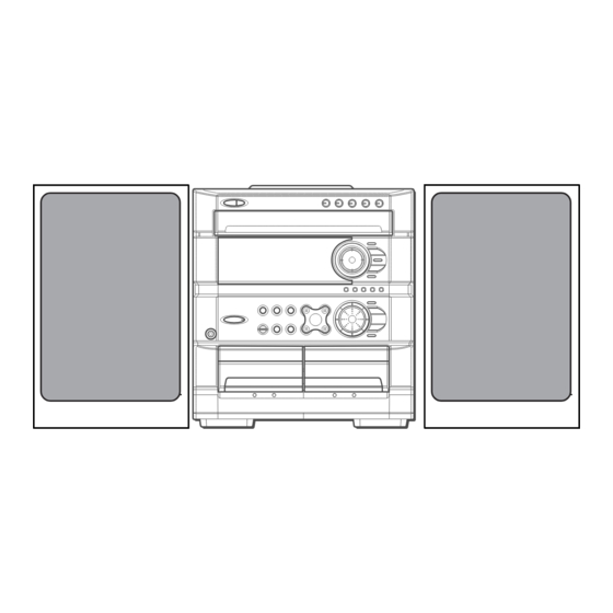
COMPACT DISC STEREO
SYSTEM
SYSTEM
Z–L720
Z–L820
• This Service Manual is the "Revision Publishing" and replaces "Simple Manual"
Z-L720 (U) / L820 (LH), (S/M Code No. 09-011-440-1T1).
• If requiring information about the CD mechanism, see Service Manual of
6ZG-1, (S/M Code No. 09-001-338-7N8).
Z-L720
Z-L820
BASIC TAPE MECHANISM : ZZM-3 PR1NM
BASIC CD MECHANISM : 6ZG-1 ZZRNIM
CD
CASSEIVER
CX–ZL720
CX–ZL820
S/M Code No. 09-012-440-1R1
SPEAKER
CONTROLLER
SX–WZL720
SX–WZL820
U
LH
REMOTE
RC–ZAS02
RC–ZAS02
Advertisement
Table of Contents

Related Manuals for Aiwa Z-L720U


Summary of Contents for Aiwa Z-L720U
- Page 1 Z-L720 Z-L820 SERVICE MANUAL COMPACT DISC STEREO BASIC TAPE MECHANISM : ZZM-3 PR1NM SYSTEM BASIC CD MECHANISM : 6ZG-1 ZZRNIM REMOTE SYSTEM SPEAKER CASSEIVER CONTROLLER Z–L720 CX–ZL720 SX–WZL720 RC–ZAS02 Z–L820 CX–ZL820 SX–WZL820 RC–ZAS02 • This Service Manual is the "Revision Publishing" and replaces "Simple Manual" Z-L720 (U) / L820 (LH), (S/M Code No.
-
Page 2: Specifications
SPECIFICATIONS <FM tuner section> <Compact disc player section> Tuning range 87.5 MHz to 108 MHz Laser Semiconductor laser (λ =780 nm) Usable sensitivity (IHF) 13.2 dBf D-A converter 1 bit dual Antenna terminals 75 ohms (unbalanced) Signal-to-noise ratio 85 dB (1 kHz, 0 dB) Harmonic distortion 0.05 % (1 kHz, 0 dB) <AM tuner section>... -
Page 3: Protection Of Eyes From Laser Beam During Servicing
PROTECTION OF EYES FROM LASER BEAM DURING SERVICING This set employs laser. Therefore, be sure to follow carefully CAUTION the instructions below when servicing. Use of controls or adjustments or performance of proce- dures other than those specified herin may result in WARNING!! hazardous radiation exposure. -
Page 4: Note On Before Starting Repair
NOTE ON BEFORE STARTING REPAIR 1. Forced discharge of electrolytic capacitor of power supply block When repair is going to be attempted in the set that uses relay circuit in the power supply block, electric potential is kept charged across the electrolytic capacitors (C101, 102) even though AC power cord is removed. - Page 5 In such a case, check also if the POWER AMPLIFIER circuit or power supply circuit has any abnormalities or not. 2-2. Regarding reset There are cases that the machine does not work correctly because the MICROCOMPUTER is not reset even though the AC power cord is re-inserted, or the software reset (pressing the STOP key + POWER key) is performed.
-
Page 6: Electrical Main Parts List
ELECTRICAL MAIN PARTS LIST REF. NO. PART NO. KANRI DESCRIPTION REF. NO. PART NO. KANRI DESCRIPTION 87-A12-317-080 C-CAP,U 0.1-50 Z F 87-A10-231-090 CAP,E 3300-80 8B-MA3-651-010 C-IC,LC876572V-5T94 87-A10-231-090 CAP,E 3300-80 87-A21-419-040 C-IC,NJM14558MD-TE2 87-A10-520-000 CAP,E 3300-35 M SMG 87-A21-577-040 C-IC,M61506FP 87-A10-520-000 CAP,E 3300-35 M SMG 87-A21-893-040 C-IC,NJM14558V-TE2 87-A21-831-010... - Page 7 REF. NO. PART NO. KANRI DESCRIPTION REF. NO. PART NO. KANRI DESCRIPTION C317 87-A12-085-080 CAP,E 0.33-50 SMG C795 87-012-286-080 CAP, U 0.01-25 C318 87-A12-085-080 CAP,E 0.33-50 SMG C796 87-012-286-080 CAP, U 0.01-25 C326 87-016-118-080 C-CAP,U0.022-25JB C797 87-A12-091-080 CAP,E 10-50 SMG C327 87-A12-317-080 C-CAP,U 0.1-50 Z F...
- Page 8 REF. NO. PART NO. KANRI DESCRIPTION REF. NO. PART NO. KANRI DESCRIPTION CN501 87-099-564-010 CONN,4P TUC-P4P-B1 C251 87-010-759-080 C-CAP,U, 0.1-25F CN601 87-099-719-010 CONN,30P TYK-B(X) C252 87-012-199-080 CAP 220P CN602 87-A60-131-010 CONN,6P V FE C253 87-012-195-080 C-CAP,U 100P-50CH CNA1 8A-NF8-653-010 CONN ASSY,9P TID-A(480) C301 87-012-358-080 C-CAP,S 0.47-10 Z F...
- Page 9 REF. NO. PART NO. KANRI DESCRIPTION REF. NO. PART NO. KANRI DESCRIPTION S825 87-A90-095-080 SW,TACT EVQ11G04M MIC C.B S826 87-A90-095-080 SW,TACT EVQ11G04M S827 87-A90-095-080 SW,TACT EVQ11G04M C602 87-A10-706-080 C-CAP,U 0.33-16 Z F S828 87-A90-095-080 SW,TACT EVQ11G04M C603 87-012-337-080 C-CAP,U 56P-50 J CH GRM S829 87-A90-095-080 SW,TACT EVQ11G04M...
-
Page 10: Chip Resistor Part Code
CHIP RESISTOR PART CODE Chip Resistor Part Coding Figure Resistor Code Value of resistor Chip resistor Dimensions (mm) Symbol Wattage Type Tolerance Resistor Code Form 1/16W 1005 0.35 1/16W 1608 0.45 1/10W 2125 1.25 0.45 1/8W 3216 0.55 TRANSISTOR ILLUSTRATION E C B E C B B C E... - Page 11 WIRING – 1 (MAIN) – 11 –...
- Page 12 SCHEMATIC DIAGRAM – 1 (MAIN 1 / 2 : AMP SECTION) – 12 –...
- Page 13 SCHEMATIC DIAGRAM – 2 (MAIN 2 / 2 : TUNER SECTION) – 13 –...
- Page 14 WIRING – 2 (FRONT) – 14 –...
- Page 15 SCHEMATIC DIAGRAM – 3 (FRONT / DECK) – 15 –...
- Page 16 WIRING – 3 (KEY CD / FAN / RELAY / MIC) – 16 –...
- Page 17 SCHEMATIC DIAGRAM – 4 (KEY CD / FAN / RELAY / MIC) – 17 –...
- Page 18 WIRING – 4 (PT : U) – 18 –...
- Page 19 SCHEMATIC DIAGRAM – 5 (PT : U) – 19 –...
- Page 20 WIRING – 5 (PT : LH) – 20 –...
- Page 21 SCHEMATIC DIAGRAM – 6 (PT : LH) – 21 –...
- Page 22 WIRING – 6 (DECK) TO FRONT C. B CN104 (FFC104) F DECK C . B 11 9 7 5 3 1 10 8 6 4 2 – 22 –...
- Page 23 IC DESCRIPTION IC, LC876572V-5T94 Description Pin No. Pin Name M-CLK Common serial clock. M-DATA Common serial data. TU-ON Tuner supply control. H: ON. O-PLL-CE Tuner PLL IC chip enable. CD dish LED5. L: ON. BIAS Recording bias control. L: ON. O-POWER Audio power ON/OFF.
- Page 24 Description Pin No. Pin Name P24/ECO FL segment P24 output/ECO setting switching input. H: ECO mode off<LH ONLY>. 60 ~ 63 P23 ~ P20 FL segment P23 ~ P20 output. P19/CST2 FL segment P19 output/Deck 2 cassette detection. L: YES. FL segment P18 output.
-
Page 25: Ic Block Diagram
IC BLOCK DIAGRAM – 25 –... - Page 26 FL (BJ824GNK) GRID ASSIGNMENT & PIN CONNECTION & ANODE CONNECTION GRID ASSIGNMENT PIN CONNECTION ANODE CONNECTION – 26 –...
- Page 27 ADJUSTMENT < TUNER / DECK / FRONT > < TUNER SECTION > 1. Clock Frequency Check Settings : • Test point : TP2 (CLK) 7. DC Balance / Mono Distortion Adjustment Method : Set to AM 1710 kHz and check that the test point is Settings : •...
- Page 28 < DECK SECTION > 10. Tape Speed Adjustment (DECK 2) 15. REC/PB Sensitivity Check (DECK 2) Settings : • Test tape : TTA–100 Settings : • Test tape : TTA–602 • Test point : TP8(Lch), TP9(Rch) • Test point : TP8(Lch), TP9(Rch) •...
-
Page 29: Cd Test Mode
CD TEST MODE 1. How to Activate CD Test Mode While pressing and holding the function button, insert the AC plug. When the test mode starts, the message, “TEST” appears on the display. 2. How to Cancel CD Test Mode Press the POWER button or remove the AC plug. -
Page 30: Mechanical Exploded View
MECHANICAL EXPLODED VIEW 1 / 1 – 30 –... -
Page 31: Mechanical Parts List
6 8B-MA3-051-010 WINDOW,DISP U A3<U> 40 88-MA1-208-210 JOINT,CABI 7 87-NF4-216-010 HLDR,LOCK 1 41 8B-MA3-011-010 CABI,REAR LH A3<LH> 8 87-B00-002-010 BADGE,AIWA 30 ABS SIL 41 8B-MA3-010-010 CABI,REAR U A3<U> 9 87-NF8-220-010 DMPR,150 42 8B-MA3-213-010 HLDR,HT-SINK B 10 86-NF9-224-010 SPR-C,LOCK 43 87-064-185-010... -
Page 32: Tape Mechanism Exploded View
TAPE MECHANISM EXPLODED VIEW 1 / 1 TERMINAL, TERMINAL,LB1 IC, EW732 IC, EW732 – 32 –... -
Page 33: Tape Mechanism Parts List
TAPE MECHANISM PARTS LIST 1 / 1 REF. NO. PART NO. KANRI DESCRIPTION REF. NO. PART NO. KANRI DESCRIPTION 8Z-ZM3-227-010 BELT,MAIN M3 8Z-ZM3-233-010 SPR-T,BRG M3 8Z-ZM3-235-010 BELT,MAIN L 84-ZM2-227-310 SPR-C,AZIMUTH 8Z-ZM1-235-010 PULLEY,MOT 87-A90-403-110 HEAD,RPH MS15R 87-045-347-010 MOT,SHU2L 70 87-A90-404-010 HEAD,EH LE15B 8Z-ZM1-232-010 GEAR,IDL FF/REW 8Z-ZM3-239-010... -
Page 34: General Speaker Disassembly Instructions (For Reference)
GENERAL SPEAKER DISASSEMBLY INSTRUCTIONS (FOR REFERENCE) Type.1 Type.4 TOOLS Insert a flat-bladed screwdriver into the position indicated by the arrows and remove the panel. Remove the screws of each speaker 1 Plastic head hammer unit and then remove the speaker units. 2 (() flat head screwdriver 3 Cut chisel How to Remove the PANEL, FR... -
Page 35: Accessories / Package List
SPEAKER PARTS LIST SX-WZL720 (YUSL) / WZL820 (YLSL) REF. NO. PART NO. KANRI DESCRIPTION 1 8B-MS3-001-010 PANEL,FR 2 8B-MS3-004-010 PANEL,TW A 3 8B-MS3-005-010 PANEL,TW B 4 8B-MS3-012-010 PANEL,TW C 5 8B-MS3-006-010 PANEL,DUCT A 6 8B-MS3-007-010 PANEL,DUCT B 7 8B-MS3-008-010 PANEL,DUCT C 8 8B-MS3-009-010 PROTECTOR,SQ 9 88-NS5-610-010... - Page 36 2–11, IKENOHATA 1–CHOME, TAITO-KU, TOKYO 110, JAPAN TEL:03 (3827) 3111 2000075 9630472 0251431 Printed in Singapore...
Need help?
Do you have a question about the Z-L720U and is the answer not in the manual?
Questions and answers