
Related Manuals for Sunwoda CIESS-R-S Series


Summary of Contents for Sunwoda CIESS-R-S Series
- Page 1 User Manual Rechargeable Li-ion Battery System Model: CIESS-R-S series Version: V 1.0 Sunwoda Energy Technology Co., Ltd.
-
Page 2: Table Of Contents
User Manual Content 1 Security Statement ................1 1.1 Safety Notes ..........2 1.1.1 Personal security ............... 2 1.1.2 Electrical security ............... 3 1.1.3 Environmental security ............3 1.1.4 Machinery security ............. 4 1.1.5 Battery Security ..............5 1.2 Safety symbols ........... 6 2 System Instruction .......... - Page 3 User Manual 4.5 Introduction to Indicator Lights ......59 5 System maintenance .......... 60 5.1 System maintenance ........60 5.2 Troubleshooting ......... 61 6 Transportation and storage requirements ......65 6.1 Transportation Requirements ......65 6.2 Storage Requirements ........66 Appendices ............
-
Page 4: Security Statement
User Manual 1 Security Statement The product must be installed and maintained by specialized personnel in accordance with local standards and regulations and in strict accordance with the installation procedures in the manual. Before transporting, storing, installing, operating, using and maintaining the equipment, read and keep this manual carefully and use the product strictly following all cautionary statements in this manual. -
Page 5: Safety Notes
User Manual emphasized in this user manual to use the equipment; Damage caused by deviation from the requirements of the operating instructions and safety warning in this user manual; Damage to the equipment caused by non-compliance of the installation and use environment with international, national or regional use standards;... -
Page 6: Electrical Security
User Manual Specific insulated tools are required during operation to avoid electric shock or short-circuit faults, and the voltage withstand level of the insulated tools must meet the requirements of local laws, regulations, standards, and specifications. Warning Dedicated protective equipment, such as protective clothing, insulated shoes, goggles, helmets, insulated gloves, etc., must be used during the operation. -
Page 7: Machinery Security
User Manual such environment. Do not store flammable or explosive materials around the equipment. Do not place the equipment near sources of heat or fire, such as fireworks, candles, heaters or other heat generating devices, as heat exposure to the equipment may result in damage to the equipment or cause a fire. -
Page 8: Battery Security
User Manual tests or beyond the validity period of the test to ensure the firmness of the tools, and not exceeding the load. Before installing the equipment into the cabinet, first make sure that the cabinet has been fixed well to avoid the cabinet being tilted and collapsed due to the unstable center of gravity, resulting in the installer being smashed and the equipment being broken and other problems. -
Page 9: Safety Symbols
User Manual which may result in battery damage or fire. Do not dismantle, modify or damage the battery (e.g. inserting strange objects, extruding with external force, immersing in water or other liquids), which may cause battery leakage, smoke, release of combustible gases, thermal runaway, fire or explosion. -
Page 10: System Instruction
User Manual product! recovery recycling! Hazard: High voltage hazard, Recyclable! careful This faces upwards and cannot No open fire. be tilted or placed upside down. Read the manual No stepping on. carefully before use! The unit vents are Ground hot, so be careful protection! about touching them! A 5-minute wait is... -
Page 11: About The Battery Box
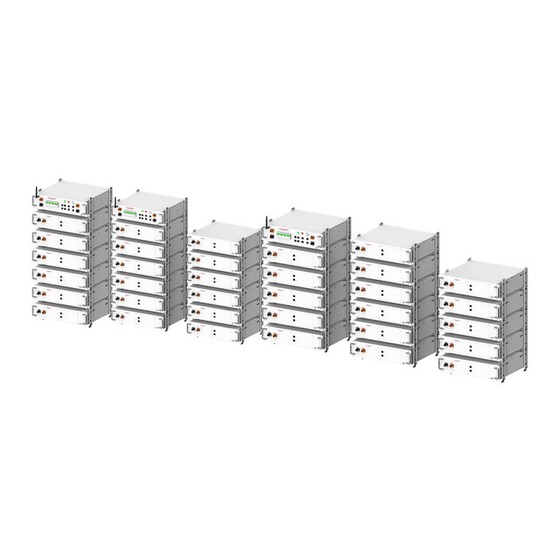
User Manual Typical Application Scenario This manual mainly introduces the elements of CIESS R-S series LiFePO4 battery energy storage system, installation method, operation approach, routine maintenance common troubleshooting, and product specifications and parameters in detail. The modules involved in the product are: battery box module and control box module. -
Page 12: About The Control Box
User Manual Communication port 1 of the daisy Link A chain Communication port 2 of the daisy Link B chain Earth Connection Grounding Point 2.3 About the control box Interface Instruction BAT+ Positive Input of Battery System BAT- Negative Input of Battery System Air Switch Disconnect Switch for DC Main Circuit CAN communication cable, parallel cable... -
Page 13: Nameplate Introduction
User Manual (WAN)/local area network (LAN) INV+ Connect to the positive terminal of PCS INV- Connect to the negative terminal of PCS Earth Grounding point Connection 2.4 Nameplate Introduction The following nameplate is for reference only, specific values subject to the real thing. Product Name and Model Product Technical... -
Page 14: Basic Accessories
User Manual 2.5.1 Basic accessories Name Illustration Name Illustration Terminal M5*10 screw Crystal Head with Resistor Aluminum Sheet metal bracket bracket Control Box Battery Box 2.5.2 Wire Harness Introduction (1)Earth wire Name Material Number Type Illustration Length Grounding harness from control box to battery box: 5619100041311 CIESS 0.18m... - Page 15 User Manual Harness * Tips:"*" indicates that the harness has an application in parallel mode. (2)Power wire Name Material Number Type Illustration Length Power harness from battery box to battery box: Power 5619100059301 CIESS 0.19m Harness 25~80-R-S Power 5619100059321 CIESS 0.9m Harness 35~80-R-S...
- Page 16 User Manual Power 5619100059391* CIESS Harness * 25~80-R-S Tips: "*" indicates that the harness is applied primarily in parallel mode. "**" indicates that the wiring harness may vary depending on the inverter brand, specifications, etc. See packing list for detailed material and material number; (3)Communication wire Name Metrial Number...
-
Page 17: Installation Guidance
User Manual communication 25~80- Harness 5619100059371* CIESS communication 25~80- Harness* COM port communication harness from control box to control box: 5619100062061* CIESS 1.5m communication 25/30- Harness* 5619100062051* CIESS 4.5m communication 35~60- Harness* 5619100062071* CIESS communication 65~80- Harness Tips:"*" indicates that the harness is applied primarily in parallel mode. 3 Installation Guidance 3.1 Cautionary notes The product must be installed by a professional in accordance... -
Page 18: System Assembly
User Manual high-temperature heat sources or low-temperature cold sources. Avoid installing equipment in areas with excessive ambient temperature changes or extreme climates. Avoid installing the equipment in a strong interference environment. Avoid installing equipment in areas where children commonly congregate to prevent access by children. -
Page 19: Assemble The Basic Bracket
User Manual Cautionary Notes: Select an indoor site, before installation, make sure the ground is level, the floor load-bearing ≥1500kg/m2, and the horizontal distance between neighboring battery packs ≥200mm. Installation must be completed by a professional in the following steps sequentially. -
Page 20: Assemble The Simple Bracket To The Box
User Manual CIESS 10 groups/40 CIESS 11 groups/44 sets 45 R-S sets 50 R-S CIESS 12 groups/48 CIESS 13 groups/52 sets 55 R-S sets 60 R-S CIESS 14 groups/56 CIESS 15 groups/60 sets 65 R-S sets 70 R-S CIESS 16 groups/64 CIESS 17 groups/68 sets 75 R-S... - Page 21 User Manual (1)Pick an indoor flat surface and stack the boxes in rows starting with the battery ones; (2)Always fasten one box with 8 (2x4) M5*12 screws before stacking the next box. At the end of the stack, the control box is always at the top of the column (Fig.
-
Page 22: Electric Connection
User Manual CIESS 35~60-R-S CIESS 65~80-R-S Figure 3.5 Stacking method for each model 3.3 Electric Connection Cautionary Note:... -
Page 23: Connect The Earth Harness
User Manual Ensure that all switches remain disconnected and all equipment is turned off and de-energized before connecting the cables. Wiring must be completed by a professional in the following sequence. Use the cable equipment provided by our company and the required harness type, do not use wires arbitrarily. - Page 24 User Manual C grounding harness Figure 3.7b Earth connection from the 2nd to 3rd columns (if equipped) (3)Use D grounding harness (5619100060311) to connect the battery system to other external grounding points such as an inverter (Fig. 3.8). D grounding harness Figure 3.8 Earth connection from Control Box to one Inverter Table 3.2 Types of grounding harnesses Type...
- Page 25 User Manual (4)Final results of earth connection D Grounding Harness A Grounding Harness...
- Page 26 User Manual D Grounding Harness A Grounding Harness B Grounding Harness D Grounding Harness B Grounding Harness C Grounding Harness A Grounding Harness Figure 3.9 Illustration of the complete earth connection effect...
-
Page 27: Connect The Power Harnesses
User Manual (CIESS 30/60/80-R-S Models as an example) 3.3.2 Connect the power harnesses A Connector Introduction The connector structure of all power harnesses is shown below (Fig. 3.10). To use, please press and hold the red button of the plug, and release it when there is a clicking sound to complete the connection. - Page 28 User Manual connected serially using the B Power Harness (5619100059321), see Figure 3.12 for wiring details. Table 3.3 shows the different power harnesses applied in different product types. Figure 3.12a. Connect the B power harness from the 1st to 2nd columns Figure3.12b.
- Page 29 User Manual Figure 3.13 Connect the C power harness (2)Connect the positive power harness: Use the D/E/F/G power harness to wire from the "Bat +" terminal of the last battery box to the "Bat +" terminal of the control box. Different product models correspond to different types of harnesses (Table 3.4);...
- Page 30 User Manual Figure 3.14a D/E Power Harness Connection Applicable types: CIESS 25/30-R-S Figure 3.14b F Power Harness Connection Applicable types: CIESS 35~60-R-S Figure 3.14c G Power Harness Connection Applicable types: CIESS 65~80-R-S D Connect power harnesses from control box to inverter The connection method of the harness at the positive and negative terminals is shown in the following figure (Fig.
- Page 31 User Manual I Power Harness H Power Harness Figure 3.15 Power line connection from control box to inverter E Final wiring effects of power harnesses I power harness D/E power harness H power harness C power harness A power harness...
- Page 32 User Manual I power harness F power harness H power harness A power harness C power harness B power harness H power harness I power harness C power harness B power harness A power harness G power harness...
-
Page 33: Connect The Communication Harness
User Manual Figure 3.16 Final effect of power line connection (CIESS 30/60/80-R-S Models as an example) 3.3.3 Connect the communication harness A. Link port communication harnesses connection The types of wiring harness involved in different models will vary depending on how the products are stacked. The types of wiring harness involved in different models and the wiring methods are shown in the following figure (Figure 3.17): Tips:... - Page 34 User Manual Figure 3.17a. Link Port Communication Harnesses Connection Applicable types: CIESS 25/30-R-S A communication harness E communication harness A communication harness B communication harness Figure 3.17b. Link Port Communication Harness Connection Applicable types: CIESS 35~60-R-S B communication harness A communication harness F communication harness Figure 3.17c.
- Page 35 User Manual Table 3.5 Application scope of Link port communication harness from battery box to control box Type Name Metarial Length Amount Number CIESS 5619100061281 1.34m 1pcs/1 25 R-S communication control harness CIESS 5619100061401 1.52m 1pcs/1 30 R-S communication control harness CIESS 5619100059351 0.85m...
- Page 36 User Manual G communication harness Crystal terminal with resistor Figure 3.18 Connection of COM port communication harness C. Lan port communication harness connection The LAN and WAN/LAN ports on the right side of the control box are the communication ports for data modules of the battery system.
- Page 37 User Manual G communication harness A communication C/D communication harness harness A communication harness G communication harness A communication harness E communication harness A communication harness B communication harness...
-
Page 38: Parallel Mode (Optional
User Manual G communication A communication harness harness B communication harness F communication harness Figure 3.20 Communication Harnesses Final Connection Effect (CIESS 30/60/80-R-S Models as an example) 3.4 Parallel mode (Optional) 3.4.1 Ground connection for parallel cabinet... - Page 39 User Manual D grounding harness Combiner box Figure 3.21a Parallel ground connections for CIESS 25/30-R-S (3-cluster parallel cabinets of CIESS 30-R-S as an example) D grounding harness Combiner box Figure 3.21b Parallel ground connections for CIESS 35~60-R-S (3-cluster parallel cabinets of CIESS 60-R-S as an example)
-
Page 40: Power Line Connection For Parallel Cabinet
User Manual D grounding harness Combiner box Figure 3.21c Parallel ground connections for CIESS 65~80-R-S (3-cluster parallel cabinets of CIESS 80-R-S as an example) 3.4.2 Power line connection for parallel cabinet J power harness K power harness Combiner box Figure 3.22a Parallel power line connections for CIESS 25/30-R-S (3-cluster parallel cabinets of CIESS 30-R-S as an example) -
Page 41: Communication Line Connection For Parallel Cabinet
User Manual J power harness K power harness Combiner box Figure 3.22b Parallel power line connections for CIESS 35~60-R-S (3-cluster parallel cabinets of CIESS 60-R-S as an example) K power harness J power harness Combiner box Figure 3.22c Parallel power line connections for CIESS 65~80-R-S (3-cluster parallel cabinets of CIESS 80-R-S as an example) 3.4.3 Communication line connection for parallel cabinet... - Page 42 User Manual H communication harness I communication harness Figure 3.23a Parallel communication line connections for CIESS 25/30-R-S (3-cluster parallel cabinets of CIESS 30-R-S as an example) Note: At the router, connect the WAN port of one single battery system with the smallest SN code.
- Page 43 User Manual Figure 3.23b Parallel communication line connections for CIESS 35~60-R-S (3-cluster parallel cabinets of CIESS 60-R-S as an example) Note: At the router, connect the WAN port of one single battery system with the smallest SN code. H communication harness K communication harness...
- Page 44 User Manual Combiner box Figure 3.24a Harnesses Connection for CIESS 25/30-R-S Parallel cabinets (3-cluster parallel cabinets of CIESS 30-R-S as an example)
- Page 45 User Manual...
- Page 46 User Manual...
-
Page 47: Operational Guidance
User Manual 4 Operational guidance 4.1 Power-Up Guidelines (1) Before powering up the system, ensure that the equipment is firmly installed, the installation location is convenient for operation and maintenance, the installation space is convenient for ventilation and heat dissipation, and the installation environment is clean and tidy. -
Page 48: Setup Data Monitoring
User Manual Figure. 4.2 4.3 Setup data monitoring Recommended to use Google Chrome, version 113.0.5672.93 (official version) (64-bit) or higher, Windows 10 for PC system version. 4.4.1 Local Data Monitoring 4.4.1.1 Data module distribution and control box address assignment for single- cabinet. (1) Change the IP of your computer PC to be automatically obtained by the following steps(Fig.4.3). - Page 49 User Manual Figure. 4.3 (2) Connect the LAN port of the control box to the network port of the PC through the RJ45 network port connector (8P), open Google Chrome and enter the URL 192.168.5.5, user name: user, password: password (Fig.4.4). Figure.
- Page 50 User Manual Figure 4.5 (4) Assign the address of the control box as "80" in the following screen (the stand-alone cabinet is the host by default), and click Set (Fig. 4.6). Figure 4.6 4.4.1.2 Data module distribution and control box address assignment for three clusters of parallel cabinet (1) Change the IP of your computer PC to be obtained automatically by following the steps below (Fig4.7).
- Page 51 User Manual Ethernet Bluetooth network connection Network 3 Figure.4.7 (2) Connect the LAN port of the control box of the main cabinet to the network port of the PC through the RJ45 network port connector (8P), open the Google Chrome browser and enter the URL 192.168.5.5, user name: user, password: password (Fig4.8).
- Page 52 User Manual (Fig4.9): wired, master cabinet, after the setup is completed, if prompted to restart the device, please wait patiently (the WAN port of the main cabinet control box is connected to the WAN interface with a standard network cable). Figure 4.9 (4) Set the battery cabinet address to "80"...
- Page 53 User Manual Figure. 4.11 (6) Connect one control box of slave cabinet LAN port to the PC computer network port through the RJ45 network port connector (8P), open the Google Chrome browser and enter the URL 192.168.5.5, user name: user, password: password. (7) Set the network access method in the following page: Wireless, Slave Cabinet, and enter the LAN WIFI name and password emitted from the master cabinet in step (5) below, and...
- Page 54 User Manual Figure. 4.13 (9) Connect the LAN port of the control box from No.2 slave cabinet to the network port of the PC through the RJ45 network port connector (8P), open the Google Chrome browser and enter the URL 192.168.5.5, user name: user, password: password. (10) Set the battery cabinet into the network in the following page: wireless, slave cabinet, and enter the LAN WIFI name and password emitted from the master cabinet in step (5) below, click...
- Page 55 User Manual Figure 4.15 (12)After connecting the three clusters of DC-side parallel lines, turn on the computer in order, connect the LAN port of the control box of master cabinet (address 80) to the network port of the PC through the RJ45 network port connector (8P), open the Google Chrome browser and enter the URL 192.168.5.5, account number: user, password: password, and set up the cluster enable for the following page "7", click Setting (Fig.
- Page 56 User Manual pages(Fig.4.17): Figure 4.17 4.4.1.4 Local data downloads Recording data, event logging and real-time data downloads can be performed from the following page (Fig.4.18):...
- Page 57 4.4.1.5 Local start/stop control BCMU start/stop control can be carried out through the following page (Fig.4.19). Figure 4.19 4.4.2 Remote Data Monitoring 4.4.2.1 Account Register Go to the webpage https://sunwoda.vidagrid.com/ to reach the following page, click and complete the registration (Fig.4.20).
- Page 58 User Manual Figure 4.20 4.4.2.2 Adding sites and equipment Login to the registered account, click Add Site in the red box location on the home page, and follow the steps below to complete the addition of the site and the master cabinet (address 80) equipment (Fig.
- Page 59 User Manual Figure. 4.21 Tips: 1. SN code should be obtained from the battery cabinet nameplate information, the length of 17 bits, remove the first character code, retain the last 16 characters as a valid SN code, enter the last 16 SN code here to bind, must ensure that the network configuration has been completed before binding SN (see 4.4.1.1 for more details).
- Page 60 User Manual above operation, please bind the SN code of "81" and "82" devices from the slave cabinets at the corresponding stations in the current interface. SN code should be obtained from the nameplate information of the corresponding slave cabinet. Remove the first character of the 17-digit SN code and retain the last 16 digits as the (...
- Page 61 User Manual Figure 4.23 (2)You can refer to the location of the red box on the following page to view the site and equipment information(Fig. 4.24). Figure 4.24 (3)You can refer to the location of the red box on the following page for viewing and exporting energy and power reports for the relevant sites and devices(Fig.
-
Page 62: System Shutdown
User Manual Figure 4.25 4.4 System shutdown Press and hold down the POWER key on the front side of the control box for 3 seconds, the running indicator goes out, pull its air switch down to place it in the off state, then the system shuts down (Fig.4.26). -
Page 63: System Maintenance
User Manual Not on 1s blinks 1 Initialization state, Starting time state, Stopping state Not on Running state Not on Fault state 5 System maintenance Hazard Operating the equipment with electricity may result in damage to the battery system or a risk of electric shock. When operating and maintaining the battery system, de- energize the battery system. -
Page 64: Troubleshooting
User Manual be inspected periodically by a professional to check whether the wiring is loose or detached, or to clean the surface and the interior of the system; if any defects are found, please contact the dealer promptly. 5.2 Troubleshooting Fault type Cause of fault Solutions... - Page 65 User Manual environmental system recovers on its range, the system own when the derates by itself. environment is restored; Please contact the after-sales service, Internal fault please do not disassemble the device by yourself; Identify the corresponding cause of Battery Feedback the malfunction in Charge/Discharge Unable to...
- Page 66 User Manual 3. check whether the PCS battery option setting is correct; 4. Check whether the CAN bus matching resistance is appropriate; 1. Confirm whether the PCS has insulation detection and reasonably configure the BMS enabling parameters; Enablement Insulation 2. Confirm whether it is configuration is not Abnormal a multi-cluster parallel...
- Page 67 User Manual message (function code) displayed on the PCS side, check the PCS function fault table to find out the corresponding fault cause; Connect the system grounding terminal effectively and reliably Enclosure System is not to each ground electrocution effectively grounded protection point as required by the installation manual;...
-
Page 68: Transportation And Storage Requirements
User Manual disassemble it by yourself; Check whether the grid Grid abnormality voltage is normal; 6 Transportation and storage requirements 6.1 Transportation Requirements Hazard Prohibit rough loading and unloading, violent vibration, shock or extrusion, prevent sunlight and rain, otherwise it may lead to short-circuit, damage (liquid leakage, rupture, etc.), fire or explosion of the battery. -
Page 69: Storage Requirements
User Manual of the battery is complete and undamaged, and that there is no odor, leakage, smoke, fire, etc. Otherwise, transportation is prohibited. When handling the battery, hold it gently and put it down, do not bump the battery, and pay attention to personal safety. The transportation packing box must be firm, and care should be taken during loading and unloading and transportation to put it down carefully and gently and take good... - Page 70 User Manual Warning The battery should be stored indoors. No direct sunlight or rain, dry and well ventilated, clean surroundings, no large amounts of infrared and other radiation, no organic solvents or corrosive gases, no metal conductive dust, etc., away from heat and fire sources.
- Page 71 User Manual organic solvents, gases and other substances. Avoid direct sunlight. The distance from the heat source should not be less than two meters. Battery maintenance is required at a maximum interval of 6 months from the date of shipment from the manufacturer; the requirements for the replenishment interval after battery discharge are as follows: Ambient temperature (30,40]°...
-
Page 72: Appendices
User Manual Appendices System technical specifications Battery Module Parameters Module type B051100S02 Module Rated Voltage (V) 51.2 Module energy (kWh) 5.12 Module size (W*D*H, unit: 443*410*135 Module weight (kg) System parameters Ⅰ CIESS CIESS CIESS CIESS CIESS CIESS System Model 25-R-S 30-R-S 35-R-S... - Page 73 User Manual System parameters Ⅱ CIESS CIESS CIESS CIESS CIESS CIESS System Model 55 R-S 60 R-S 65 R-S 70 R-S 75 R-S 80 R-S Battery Pack Quantity Rated voltage (V) 563.2 614.4 665.6 716.8 819.2 Min. voltage 492.8 537.6 582.4 627.2 716.8...
Need help?
Do you have a question about the CIESS-R-S Series and is the answer not in the manual?
Questions and answers