
Related Manuals for Sunwoda Atrix basic-5 Series


Summary of Contents for Sunwoda Atrix basic-5 Series
- Page 1 User Manual Atrix basic-5/10/15/20 Series Residential energy storage systems Version:V1.0...
-
Page 3: Table Of Contents
Content 1 Safety precaution ........................3 Storage and installation environment ................3 Battery safety guidelines ....................3 Warning signs and stickers .................... 3 Emergency handling ...................... 4 1 Product Description ........................5 Product Introduction ..................... 5 Product appearance description ................... 6 2 Installation Guide ........................ -
Page 4: Safety Precaution
Defected or damaged batteries shall not be charged or discharged Use the product only with inverters authorized by Sunwoda Energy, or consult Sunwoda Energy's product engineers. For compatible list inverters, please visit: https://www.sunwodaenergy.com/download. 1.3 Warning signs and stickers... -
Page 5: Emergency Handling
Warning Protective Earth High temperature (connector) Warning Protective Earth High Voltage (general identification) 5 m i n Wait 5 min till fully discharged Do not short circuit Keep away from children (cut off power) Fragile Do not get wet 1.4 Emergency handling Wear personal protective equipment (PPE) such as goggle, facemask, insulated gloves and boots. -
Page 6: Product Description
• The system adopts IP20 protection design to support indoor use. System Diagram Optional WiFi Internet GPRS Atrix basic DC Power cable Signal cable Wireliss communication Products within the dotted line are provided by SUNWODA ENERGY... -
Page 7: Product Appearance Description
1.2 Product appearance description Product size chart: The battery module size diagram and effect diagram are shown in the following figure: Size: W*D*H=443*410*135 mm Weight: 45kg Dimensions of module... -
Page 8: Installation Guide
Battery module diagram Product Front Panel Definition: Item Function Note .BAT- Battery output negative interface POWER Battery module switch button BAT+ Battery output positive interface COM1 Communication interface with PCS Automatic addressing and internal CAN COM2 communication interface Automatic addressing and internal CAN COM3 communication interface One-key open interface... -
Page 9: Physical Installation Requirements
• Avoid rain and snow • Avoid flood-prone locations • Install under shed if possible • 3 feet of clearance from doors, windows, driveways, or other batteries • Keep away from heating equipment. • Protection against corrosive chemicals • Prevent water from spilling e. - Page 10 basic- basic- Atrix Atrix : : basic- basic- Atrix Atrix : : b. Weight 45kg (99.2lbs) For 2 persons...
-
Page 11: Preparation Of Installation Tools
2.1.3 Preparation of installation tools Tools Electric screwdriver Wrench (M5 sleeve) Personal Protective Equipment Safety gloves safety shoes 2.1.4 Unboxing guide Unpacking checklist Components M5*10 screw Data display box (Optional Feet X4 Battery accessory Racks X4 PCS-RS485/CAN Positive wire PCS-RS485/CAN Negative wire Power on cable communication... -
Page 12: Installation Steps
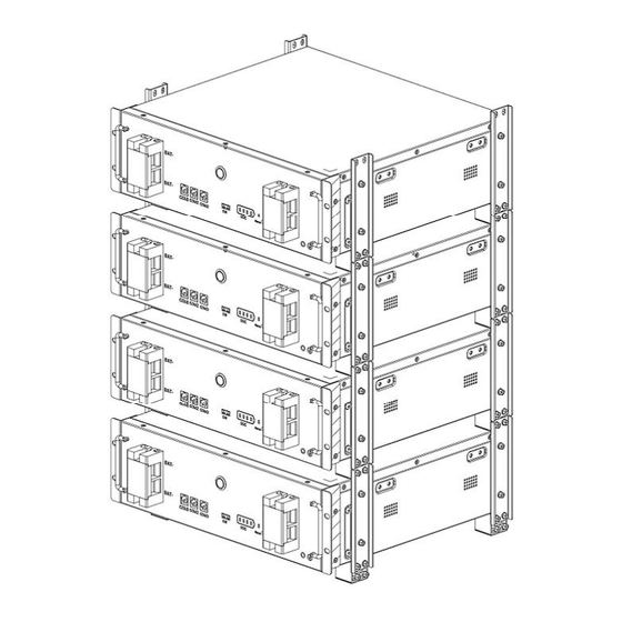
2.2 Installation steps 2.2.1 Installation step 1)Feet racket installation Take out the 4PCS feet and rackets to install. 2) Easy racket installation Install simple rackets on both sides of the battery module (including simple rackets with feet) - Page 13 3) Battery module installation a. Lay the battery module with simple racket (including feet) on the horizontal floor (Adjust feet to make the battery module horizontal if the floor is not flat). b. Install other battery modules with simple racket one on one. Fix the structure with M5*10 screw after the stack-up.
- Page 14 4) Data display box installation (Optional) Function and operation introduction of data display box: 1) Display control of LCD screen or segment code screen 2) Communication between battery and PCS 3) Remote operation, parameter set, software update 4) Compatible with multi series of rack type of product 5) Optional based on requirement of customer and system ...
-
Page 16: Electrical Connection
3 Electrical connection 3.1 Grounding Grounding point Introduce the product ground point to the nearby ground point 3.1.1 Connector installation Schematic diagram of power wiring... - Page 17 Connector installation instructions The power cable connection is shown in the figure, press and hold the red unlock button, and there is a clicking sound for the plug connection. Step 1: take the 1PC double-ended crimping φ8 OT Step 2: Bend the cable and lock the other end terminal wire number three, and lock the upper of the OT terminal in the underside hole of the terminal hole of the bottom product at one end.
-
Page 18: Guide Of Electrical Connection
3.1.2 Guide of electrical connection Electrical connection for single module shown as follows, PCS: 51.2V input Electrical connection Wire specifications Mark Battery module grounding With grounding terminal Connect the battery negative with PCS- to BAT- 25mm²,1500mm PCS negative, typical color black. Connect the battery positive with PCS+ to BAT+ 25mm²,1500mm... - Page 19 One cluster of parallel connection shown as follows, PCS: 51.2V input 接地 Electrical connection Wire specifications Mark Battery module grounding With grounding terminal Connect the battery negative with PCS- to BAT- 25mm²,1500mm PCS negative, typical color black. Connect the battery positive with PCS+ to BAT+ 25mm²,1500mm PCS positive, typical color...
- Page 20 suggest Positive wiring between battery By local provide 25mm², modules, typical color orange/red. Connect the battery with BAT-CAN, 8P8C Type 5 Shielded BAT-COM3 to BAT-COM2 typical color GRAY network cable,220mm Note: 1) The parallel wiring between the battery packs is pressed with a 25mm² wire at the installation site to the M8 OT terminal with a wire length of 320mm.
- Page 21 Electrical connection Wire specifications Mark Battery module grounding With grounding terminal Connect the battery negative with PCS- to BAT- 25mm²,1500mm PCS negative, typical color black. Connect the battery positive with PCS+ to BAT+ 25mm²,1500mm PCS positive, typical color orange/red. Connect the display box with PCS- 8P8C Type 5 Shielded CAN to PCS-CAN CAN, typical color GRAY...
- Page 22 Electrical connection Wire specifications Mark Battery module grounding With grounding terminal Connect the battery negative with PCS- to BAT- 25mm²,1500mm PCS negative, typical color black. Connect the battery positive with PCS+ to BAT+ 25mm²,1500mm PCS positive, typical color orange/red. Connect the battery with PCS-CAN, 8P8C Type 5 Shielded BAT-COM1 to PCS-CAN typical color GRAY...
- Page 23 Two clusters of parallel connection with data display box shown as follows, (Optional for data display box), PCS: 51.2V input Electrical connection Wire specifications Mark Battery module grounding With grounding terminal Connect the battery negative with PCS- to BAT- 25mm²,1500mm PCS negative, typical color black.
-
Page 24: System Commissioning
Connect the battery with BAT-CAN, 8P8C Type 5 Shielded BAT-COM3 to BAT-COM2 typical color GRAY network cable,2000mm Connection with one-button power Power on cable,250mm on function, paired connection Battery positive to positive bus- 600V,700A, By local provide bars Recommended value Battery negative to negative bus- 600V,700A, By local provide... -
Page 25: System Power Off
4.2 System power off ① Switch off the inverter (if inverter has the switch button) ② Press POWER button for more than 3s, the system is closed, screen and POWER button go out. 4.3 System configuration a. Download and install PowerLite APP The battery parameter setting and remote monitoring can be realized through the APP software (PowerLite), please go to the App Store or Google Play to search for "PowerLite"... - Page 26 ② ① ③ Note: If you have already registered a login account, please ignore this step. 3) Configure the network (You can check the Bluetooth SN code of the battery device at the antenna position of the control module) ①Click "SmartConfig", ②Select the Bluetooth device corresponding to the battery, ③Enter the WiFi network account and WiFi password, ④Click "SmartConfig"...
- Page 27 ⑤ ③ ② ④ ① d. Select inverter manufacturer After the site/device is added successfully, ①Click to enter the corresponding site, ②Click the Bluetooth SN code of the battery device to enter the battery interface, and you can view the device data, ③Click “Setting”...
-
Page 28: Maintenance And Troubleshooting
5 Maintenance and troubleshooting 5.1 Routine maintenance Maintenance charge every 6 months From the date of manufacturer shipment, the battery shall be maintained every 6 months. Action must be taken in case SOC reaches 0% according to, Ambient temperature Must be recharged within (45, 50] °C 7 days... -
Page 29: Warehouse Storage Guidelines
The LED cannot wake up during 1. If the LED is off, the POWER Please contact the supplier to repair or system operation button is faulty or the button replace the control module wiring is loose 2. If the LED still does not light up after restarting, the LED is faulty Abnormal battery Communication disconnection... -
Page 30: Storage
1) Product certificate (both in Chinese and English); 2) Product use (installation) manual (both in Chinese and English); 3) Product packing list (both in Chinese and English); 4) Factory inspection report (both in Chinese and English). Clean battery Regular cleaning of the battery system is recommended. If the case is dirty, use a soft dry brush or dust collector to remove the dust. -
Page 31: Detailed Parameter
8 Detailed parameter Table 8.1 System parameter Item Parameter Note Module model B051100P01 Rated voltage 51.2V Rated energy 5kWh System Model Atrix basic-5 Atrix basic-10 Atrix basic-15 Atrix basic-20 Parallel No. Rated energy 5kWh 10kWh 15kWh 20kWh Rated charging and discharging 100A 150A 200A...
Need help?
Do you have a question about the Atrix basic-5 Series and is the answer not in the manual?
Questions and answers