VERDER CARBOLITE GERO GHA 12/1050 Installation, Operation And Maintenance Instructions
1200c g-range tube furnace
Hide thumbs
Also See for CARBOLITE GERO GHA 12/1050:

Related Manuals for VERDER CARBOLITE GERO GHA 12/1050


Summary of Contents for VERDER CARBOLITE GERO GHA 12/1050
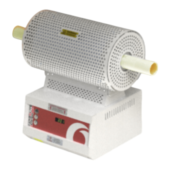
- Page 1 Installation, Operation and Maintenance Instructions 1200°C G-Range Tube Furnace - GHA Model: 1050mm 3508 Controller GHA 12/1050 + 3508 Controller MEN-GHA121050-002_3508 09-01-2019...
-
Page 2: Table Of Contents
Contents This manual is for guidance on the use of the Carbolite Gero product specified on the front cover. This manual should be read thoroughly before unpacking and using the furnace or oven. The model details and serial number are shown on the back of this manual. - Page 3 3.8.7 To pause (hold) a program 3.8.8 To stop and reset a program 3.8.9 To run a different program (P10 and P25) 3.8.10 Program Status 3.8.11 Program Hold with Holdback 3.8.12 Power Failure Recovery 3.8.13 Alarms 3.8.14 Program Example 1 3.8.15 Program Example 2 Controller Options...
- Page 4 Navigation Diagram 6.0 Operation Operating Cycle General Operating Advice Operator Safety Tube Life Pressure Gas Tightness 6.7 Running at Low Temperatures 7.0 Maintenance General Maintenance Maintenance Schedule 7.2.1 Cleaning Calibration After-Sales Service Recommended Spare Parts and Spare Parts Kit 8.0 Repairs and Replacements Safety Warning - Disconnection from Power Supply Safety Warning - Refractory Fibre Insulation Temperature Controller Replacement...
-
Page 5: Symbols And Warnings
1.0 Symbols and Warnings 1.0 Symbols and Warnings Switches and Lights Instrument switch: when the instrument switch is operated the temperature control circuit is energised. Heat light: the adjacent light glows or flashes to indicate that power is being supplied to the elements. General Warnings DANGER –... -
Page 6: Installation
2.0 Installation 2.0 Installation Unpacking and Handling When unpacking or moving the product always lift it by its base or by both ends of the main body. Never lift it by its work tube or the surrounding insulation. Use two or more people to carry the product and control box. - Page 7 2.0 Installation Ensure that the product is placed in such a way that it can be quickly switched off or disconnected from the electrical supply. This horizontal tube product is supplied with the controls in an integral base (or, to order, with the base control panel blanked off and the controls in a separate box).
-
Page 8: Work Tubes And Fittings
2.0 Installation Work Tubes and Fittings Tubes of various diameters and lengths may be fitted. Type C: minimum length for the product. Type D: 400 mm longer than C, to allow for the fitting of end seals. A pair of removable 'end adaptors' form part of the end insulation. These may be blank (no hole) or may have a hole to suit a work tube, depending on the customer order. - Page 9 2.0 Installation Fig 1 - Insulating Plug (standard length tube) Tube Insulating Plug Stem Fig 2 - Insulating Plug (long work tube)
-
Page 10: Electrical Connections
2.0 Installation Clamp Seal plate 'O' Ring seal D Seal sleeve Clamp seal End plate Clamp End plate Clamp seal (between Seal sleeve and Clamp D Seal sleeve Seal plate & 'O' Ring seal (underneath clamp) Tube Fig 3 'Twin Clamp' End Seal For assembly details refer to the separate work tube end seal manual. - Page 11 2.0 Installation Check the product rating label before connection. The supply voltage should agree with the voltage on the label and the supply capacity should be sufficient for the current on the label. The supply should be fused at the next size equal to, or higher than the current on the label.
-
Page 12: Reconfiguring And Adjusting For Voltage
2.0 Installation 2.5 Reconfiguring and Adjusting for Voltage The standard single-phase models can operate over the voltage range 200 - 240 V. The 2-phase models can operate over the range 380/220 V to 415/240 V. The 3-phase models can operate over the range 380/220 V to 415/240 V. The product is wired according to the original order and conversion from 1-phase to 2- phase or 1-phase to 3-phase is not possible. -
Page 13: 3508 Controller
3.0 3508 Controller 3.0 3508 Controller PID control This controller uses PID (Proportional Integral Derivative) temperature control. This type of control uses a complex mathematical control system to adjust the heating power and achieve the desired temperature. 3508P1 The 3508P1 is a digital temperature controller which uses PID algorithm to give excellent temperature control when properly set. -
Page 14: Basic Operation
3.0 3508 Controller Basic Operation Alarm Indicator Power Output Indicator Not Used Runs, Holds, Resets the current program Page Scroll Down Power Output Percentage Program Setpoint Temperature (PSP) when a program is running Setpoint Temperature (SP) when basic controlling... -
Page 15: Controller Layout
3.0 3508 Controller Measurement Temperature Measurement Units 3.5.1 Controller Layout 3.5.2 Keys A/ Man Disabled Runs, Holds or Resets the current program. Hold down for 3 RUN/ HOLD seconds to Reset. Scrolls through the page headings. Hold down for 3 seconds Page Key to access further levels, pass codes are required. -
Page 16: Resetting The Programmer
3.0 3508 Controller The controller will immediately attempt to reach the set temperature and maintain it. This will cause the product to heat as quickly as possible which may not be appropriate where the product contains sensitive ceramic components. For products with ceramic components, e.g. -
Page 17: Setting Up Controller
3.0 3508 Controller To Enter Level 2: 1. Press and hold page for 3 seconds. The display will show “Access Goto Level 1” 2. Press up to select level 2. After a short pause the display will show “Access Pass code”. 3. -
Page 18: Units
3.0 3508 Controller 3.7.3 Units Press page until "Units" is displayed. Press up or down to select: Celsius Fahrenheit Kelvin 3.7.4 Language The text on the 3508 Controller can be shown in different languages, this can only be set at the factory and therefore must be specified at the time of placing an order. Programming 3.8.1 Programming Notes Programs can be created in Level 1 or Level 2 of the 3508 Controller. -
Page 19: Holdback
3.0 3508 Controller To alter parameters or segments of an operating program, this program must be held or reset. Press RUN/ HOLD to pause the program, or press RUN/ HOLD for 2 seconds to reset. 3.8.2 Holdback Holdback can be used to prevent the program from operating ahead of the actual heating or cooling. -
Page 20: Program Cycling
3.0 3508 Controller 4. ‘Dev Lo’ Wait until the measured temperature drops below a fixed* threshold by an amount ‘WaitVal’ set for that segment. * The fixed threshold used by deviation parameters is set in the configuration level of the programmer and if required should be requested when purchasing a product from Carbolite Gero. -
Page 21: Running A Program
3.0 3508 Controller Holdback Type Press scroll until the display shows 'Holdback Type'. If required, press up or down to select 'Off', 'Low', 'High' or 'Band'. Target Setpoint (Visible only for Rate, Time and Step segments) Press scroll until the display shows 'Target SP'. Press up or down to set a value. -
Page 22: To Pause (Hold) A Program
3.0 3508 Controller 3.8.7 To pause (hold) a program Press RUN/HOLD Press page until 'Program Status Reset' appears Press scroll until the cursor moves to 'Reset' Press up or down to select 'Hold' RUN/HLD will be displayed 3.8.8 To stop and reset a program Press and hold RUN/HOLD Press page until 'Program Status Reset' appears... -
Page 23: Program Hold With Holdback
3.0 3508 Controller Current program number (P10 and P25 only) Current segment number Time remaining for that segment Further presses of the scroll key while a program is operating will reveal additional information: Status. This can be changed to 'Hold', 'Reset' or 'Run' by pressing up or down Program Setpoint (PSP) Current Segment Type. -
Page 24: Program Example
3.0 3508 Controller ALM (Alarm) indicator. The alarm may also switch an output – usually a relay to allow external devices to operate when an alarm occurs. Alarms only operate if they have been configured and are dependent on customer requirements. How to acknowledge an alarm will depend on the type of latching which has been configured. - Page 25 3.0 3508 Controller 12. Press scroll until 'End Type' is displayed. Press up or down to select 'Reset' 13. Press page and scroll together to return to the home display. To run the program either press RUN/HOLD or: 14. Press page until 'Program Status' is displayed 15.
- Page 26 3.0 3508 Controller Time Display Examples 10:05:3 Min/Sec/10th Sec 21:10:05 Hour/Min/Sec 196:10 Hour/Min Segment Type 'Rate' Type 'Dwell' Type 'Step' Type 'Dwell' Type 'Time' Type 'End' Target 400°C Duration 30 min Target 600° Duration 30 min Target 200° End Type 'Reset' Rate 5.0°/Min Time 120 min 3.8.15 Program Example 2...
- Page 27 3.0 3508 Controller 5. Press scroll until 'Cycles' is displayed. Default ‘1’ 6. Press scroll until 'Segment 1' is displayed 7. Press scroll until 'Segment Type' is displayed. Press up or down to select ‘Time’ 8. Press scroll until 'Holdback Type' is displayed. Default ‘Off’ 9.
-
Page 28: Controller Options
3.0 3508 Controller Segment Type 'Time' Type 'Rate' Type 'Step' Type 'Dwell' Type 'Call' Type 'End' Target 600°C Target 400°C Target 200°C Duration 30 min Call prog 3 End Type 'Dwell' Duration 30min Rate 2°C/min H back type 'High' Call cycles 2n * Segment 4 'Holdback Value' 5°C ** P10 and P25 only *** Program 3 Example... -
Page 29: Digital Communications - Rs232
3.0 3508 Controller 3.9.1 Digital Communications - RS232 If the RS232 option is supplied, the furnace is fitted with one sub-miniature D- socket connected to the controller comms module. RS232 is suitable for direct connection to a personal computer (PC) using a “straight through” cable as follows (the linked pins at the computer end are recommended but may not be necessary). -
Page 30: Remote Input And Output (Analogue Communications)
3.0 3508 Controller Temperature Controller Fuse (2A) Supply Load Normally open relay contacts Relay Output 240V 2A The purpose of the 2 amp fuse is to break the circuit to prevent overloading on the circuit due to high voltage. The instrument configuration and parameters available to the operator depend on the customer requirements. -
Page 31: Temperature Controller Replacement
3.0 3508 Controller set to on, then the relay closes during the segment and a small 1 appears in the top left of the screen. If more than one program segment output is fitted, then there are extra boxes depending on how many event outputs there are. 3.10 Temperature Controller Replacement Before handling the controller: wear an anti-static wrist strap or... -
Page 32: Operator Level 1 - No Program Running
3.0 3508 Controller 3.11.1 Operator Level 1 - No Program Running Home Display Controller identity when using more than one controller Read Only Black = Progress Page Key White = Return Scroll Key Visible Parameters depend on the Segment Type... -
Page 33: Operator Level 1 - Program Running
3.0 3508 Controller 3.11.2 Operator Level 1 - Program Running Home Display Controller identity when using more than one controller Read Only Black = Progress Page Key White = Return Scroll Key See previous diagram: Operator Level 1- No Program Running... -
Page 34: Supervisor Level
3.0 3508 Controller 3.11.3 Supervisor Level 2 To enter Level 2 Scroll Key Level 2 Locked before Pass Code entered Level 1 Home Display Unlocked Level 2 Home Display Black = Progress See previous diagram: Page Key Operator Level 1- No Program Running Hold Page Key for 3 seconds If configured Arrow Key... -
Page 35: 3508 Dual Loop Cascade Control (If Fitted)
4.0 3508 Dual Loop Cascade 4.0 3508 Dual Loop Cascade Control (if fitted) Principle of Cascade Control When cascade control is fitted, the Load Loop 3508 senses the temperature of the workload, and the Element Loop 3508 senses the element temperature. Depending on the oven or furnace model, the Load Thermocouple may be in a fixed position, or may be movable. - Page 36 4.0 3508 Dual Loop Cascade Home Display View Load Loop View Element Loop View The Element Loop should never be adjusted. Note that the elements usually run at a higher temperature than the load.
- Page 37 4.0 3508 Dual Loop Cascade Because the details of the customer’s cascade application (in particular the nature of the load) are generally not known, the feed forward parameter (FF Trim) is made easily accessible in level 2 (Refer to instrument operating instructions). Its default setting is 2%.
- Page 38 4.0 3508 Dual Loop Cascade Power Limit View...
-
Page 39: Bypassing Cascade Control
4.0 3508 Dual Loop Cascade Bypassing Cascade Control This applies where the Control Thermocouple is a removal probe (e.g. in a tube furnace), or where for other reasons it may be required to operate the furnace or oven directly from the Element Loop. To operate without Cascade Control the load thermocouple has to remain connected at all time;... -
Page 40: 2132 Over-Temperature Controller Description (If Fitted)
5.0 2132 Over-Temperature 5.0 2132 Over-Temperature Controller Description (if fitted) Description Alarm Light Page Scroll D Down Display This over-temperature controller is fitted and supplied ready to use by Carbolite Gero. It is a digital instrument with a latching alarm, requiring no additional panel controls. The controller features easy setting of over-temperature setpoint and reading of current temperature by the over-temperature sensor. -
Page 41: Operation
5.0 2132 Over-Temperature 5.2.2 Operation When switched on, the controller lights up, goes through a short test routine and then displays the measured temperature or the over-temperature setpoint. The page key allows access to parameter lists within the controller. A single press of the page key displays the temperature units, normally set to °C;... -
Page 42: Audible Alarm
5.0 2132 Over-Temperature Audible Alarm If an audible alarm is supplied for use with the over-temperature controller, it is normally configured to sound on over-temperature condition and to stop sounding when the alarm is acknowledged as given in section 5.2. Note: the alarm may sound during controller start-up. -
Page 43: Operation
6.0 Operation 6.0 Operation Operating Cycle This product is fitted with an instrument switch which cuts off power to the control circuit. Connect the product to the electrical supply. Turn on the instrument switch to activate the temperature controllers. The controllers illuminate and go through a short test cycle. -
Page 44: Tube Life
6.0 Operation Switch off the heater switch whenever loading or unloading the product. The elements are isolated when the heater switch is OFF. This switch cuts both sides of the circuit via a contactor. Tube Life A ceramic work tube may crack if work pieces are inserted too quickly or at temperatures below 900 °C (when the tube is more brittle). -
Page 45: Gas Tightness
6.0 Operation Gas Tightness Work tubes of IAP material are impervious. Sillimanite may look similar but is porous. Ensure that the correct tube material is in use before connecting and using gases other than inert gases, such as nitrogen. 6.7 Running at Low Temperatures The power limit may be adjusted to a low level in order to achieve better control when operating the product at a low temperature. -
Page 46: Maintenance
7.0 Maintenance 7.0 Maintenance General Maintenance Preventive rather than reactive maintenance is recommended. The type and frequency depends on the product use; the following are recommended. Maintenance Schedule CUSTOMER QUALIFIED PERSONNEL DANGER! ELECTRIC SHOCK. Risk of fatal injury. Only electrically qualified personnel should attempt these maintenance procedures. - Page 47 7.0 Maintenance rect positioning Seals (if fitted) Check all seals and O-rings and clamps Performance Element Circuit Electrical measurement Measure the current drawn on each Power Consumption phase / circuit Check whether the cooling fans are work- Cooling Fans (if fitted)
-
Page 48: Cleaning
7.0 Maintenance 7.2.1 Cleaning Soot deposits may form inside the furnace, depending on the process. At appropriate intervals remove these by heating as indicated in the General Operation Notes. The product's outer surface may be cleaned with a damp cloth. Do not allow water to enter the interior of the case or chamber. -
Page 49: Repairs And Replacements
8.0 Repairs and Replacements 8.0 Repairs and Replacements Safety Warning - Disconnection from Power Supply Immediately switch the product off in the event of unforeseen circumstances (e.g. large amount of smoke). Allow the product to return to room temperature before inspection. Always ensure that the product is disconnected from the electrical supply before repair work is carried out. -
Page 50: Solid-State Relay Replacement
8.0 Repairs and Replacements Solid-state Relay Replacement Disconnect the product from the power supply and remove the appropriate cover as given above. Make a note of the wire connections to the solid state relay and disconnect them. Remove the solid state relay from the base panel or aluminium plate. Replace and reconnect the solid state relay ensuring that the bottom of it has good thermal contact with the base panel or aluminium plate. -
Page 51: Element Replacement
8.0 Repairs and Replacements Element Replacement See section 8.2 - wearing a face mask is required. Disconnect the product from the electrical supply. Remove all outer guards, meshes and terminal covers from the product body. For a horizontally mounted product remove the product body from its base; to reach the bolts or screws that fix the body to the base, remove the back panel from the base. -
Page 52: Fuse Replacement
8.0 Repairs and Replacements Fuse Replacement Fuses are marked on the wiring diagram with type codes, e.g. F1, F2. For more information on fuses refer to section 11.0. Depending on model and voltage, the different fuse types may or may not be fitted. If any fuse has failed, it is advisable for an electrician to check the internal circuits. -
Page 53: Fault Analysis
9.0 Fault Analysis 9.0 Fault Analysis Furnace Does Not Heat Up The HEAT The heating element Check also that the SSR is working light is ON has failed correctly The controller shows a The HEAT The thermocouple has broken or has very high temperature light is OFF a wiring fault... -
Page 54: Product Overheats
9.0 Fault Analysis Product Overheats Product only heats up The controller when the instrument shows a very high The controller is faulty switch is ON temperature The thermocouple may be The controller faulty or may have been shows a low removed out of the heating temperature chamber... -
Page 55: Wiring Diagrams
10.0 Wiring Diagrams 10.0 Wiring Diagrams 10.1 WA-11-31 Connections below show single phase with safety switches and over-temperature control. F1, F2, F3 Fuses Filter R1/1, R1/2 Relay Contactor Relay Temperature Controller Cables Over-Temperature Controller Blue Over-Temperature Thermocouple Control Thermocouple GR/Y Green + Yellow Solid State Relay Grey Safety Switch... -
Page 56: Wa-U3-31
10.0 Wiring Diagrams 10.2 WA-U3-31 Connections below show 3-phase +N with safety switches and over-temperature control. - Page 57 10.0 Wiring Diagrams F1, F2, F3 Fuses Filter (if fitted) Controller Control Thermocouple Cables Over-Temperature Controller Blue Over-Temperature Thermocouple R1, R2, R3 Relay Black R1/1, R1/2, R2/1, R2/2, R3/1, R3/2 Relay contactor GR/Y Green + Yellow Instrument Switch(es) Grey Safety Switch Pink Element Solid State Relay...
-
Page 58: Fuses And Power Settings
11.0 Fuses and Power Settings 11.0 Fuses and Power Settings 11.1 Fuses F1 - F2: Refer to the circuit diagrams. GEC Safeclip of the type shown Fitted if supply cable fitted. Internal (glass type F up to 16 A) Supply Fitted on board to some types 38 mm x 10 mm type F fitted on Fuses... -
Page 59: Power Settings
11.0 Fuses and Power Settings 11.2 Power Settings The power limit settings (OP.Hi) for this model is as follows. The figures represent the maximum percentage of time that controlled power is supplied to the elements. Do not attempt to "improve performance" by setting a value higher than the one from the table. -
Page 60: Specifications
12.0 Specifications 12.0 Specifications Carbolite Gero reserves the right to change the specification without notice. All models have cylindrical elements with wire formed in the surface of the insulation material. All models can accept work tubes up to a maximum outside diameter of 170 mm. All models have a maximum operating temperature of 1200 °C (1100°C continuous). - Page 61 Notes Service Record Engineer Name Date Record of Work...
- Page 62 The products covered in this manual are only a small part of the wide range of ovens, chamber furnaces and tube furnaces manufactured by Carbolite Gero for laboratory and industrial use. For further details of our standard or custom built products please contact us at the address below, or ask your nearest stockist.
Need help?
Do you have a question about the CARBOLITE GERO GHA 12/1050 and is the answer not in the manual?
Questions and answers