Table of Contents
Advertisement
Quick Links
Titelseite MIT/OHNE Titelfoto
ohne Beschnitt in RGB
Title page WITH/WITHOUT title picture
without trimming in RGB
Edition
10/2023
OPERATING INSTRUCTIONS
SIMOTICS A
Synchronous motors
1FU9
www.siemens.com/drives
wenn möglich in gleicher Schriftgruppe bleiben!
groß
System
36
Produktgruppe
18
Titel
13
Dokuklasse
12
URL
9
Ausgabe
11
Fokus linie immer an die Höhe des Textes anpassen!!!
Focus line always adjust in height to the text!!!
Logo buffer zone
mittel
klein
30
26
16
14
12
11
11
10
9
9
9
7,5
An unterer Zeile ausgerichtet
Abstände zwischen den Textfeldern einhalten
Aligned to the bottom line
Keep the distances between the text fields
Advertisement
Table of Contents

Related Manuals for Siemens SIMOTICS A 1FU9


Summary of Contents for Siemens SIMOTICS A 1FU9
- Page 1 Focus line always adjust in height to the text!!! Edition 10/2023 OPERATING INSTRUCTIONS SIMOTICS A An unterer Zeile ausgerichtet Abstände zwischen den Textfeldern einhalten Synchronous motors Aligned to the bottom line 1FU9 Keep the distances between the text fields www.siemens.com/drives...
- Page 3 Introduction Fundamental safety instructions Safety information SIMOTICS A Description Synchronmotoren 1FU9 Preparing for use Assembly Operating Instructions Electrical connection Commissioning Operation Maintenance Spare parts Disposal Technical data 10/2023 A5E46712792A...
- Page 4 Note the following: WARNING Siemens products may only be used for the applications described in the catalog and in the relevant technical documentation. If products and components from other manufacturers are used, these must be recommended or approved by Siemens. Proper transport, storage, installation, assembly, commissioning, operation and maintenance are required to ensure that the products operate safely and without any problems.
-
Page 5: Table Of Contents
1.2.5 Websites of third-party companies..................11 SIMOTICS documentation ....................11 Service and support ......................12 1.4.1 Siemens Industry Online Support on the Web..............12 1.4.2 Spare parts services ......................13 Important product information ..................14 1.5.1 Intended use/foreseeable misuse..................14 1.5.1.1... - Page 6 Table of contents 4.3.3 Cooling and ventilation ...................... 33 4.3.3.1 Machines with a fan......................34 4.3.3.2 Machines without a fan (optional)..................34 4.3.4 Bearings of synchronous machines..................35 4.3.5 Balancing........................... 35 4.3.6 Types of construction/method of installation ..............35 4.3.7 Degree of protection ......................
- Page 7 Table of contents 6.3.3.2 Checking the insulation resistance and polarization index of the winding......56 Installing the machine......................59 6.4.1 Preparing the assembly area....................59 6.4.2 Lift the machine to where it will be mounted and position it ..........59 Alignment and fastening....................
- Page 8 Table of contents Final checks ........................81 Commissioning ............................ 83 Reference to chapter Safety instructions ................83 Measures before commissioning ..................83 8.2.1 Checks prior to commissioning................... 83 8.2.2 Mechanical checks ......................84 8.2.3 Insulation resistance and polarization index ............... 85 8.2.4 Checking the machine cooling ...................
- Page 9 Table of contents 10.3.1 Danger when openly storing rotors .................. 104 10.4 Inspection and maintenance .................... 105 10.4.1 Safety instructions for inspection and maintenance ............105 10.4.2 Inspections in the event of faults..................106 10.4.3 First inspection after installation or repair................. 106 10.4.4 General inspection......................
- Page 10 Table of contents 1FU9 Operating Instructions, 10/2023, A5E46712792A...
-
Page 11: Introduction
Introduction About SIMOTICS Description SIMOTICS is the Siemens family of electric motors addressing the complete motor spectrum in Digital Industry. About this manual 1.2.1 Content To illustrate possible application areas for our products, typical use cases are listed in this product documentation and in the online help. -
Page 12: Target Group
This document contains recommendations relating to third-party products. Siemens accepts the fundamental suitability of these third-party products. You can use equivalent products from other manufacturers. Siemens does not accept any warranty for the properties of third-party products. 1.2.2 Target group... -
Page 13: Standard Scope
This document may contain hyperlinks to third-party websites. Siemens is not responsible for and shall not be liable for these websites and their content. Siemens has no control over the information which appears on these websites and is not responsible for the content and information provided there. -
Page 14: Service And Support
Not all documentation classes are available for every SIMOTICS / SIMOGEAR / SINAMICS product. Service and support 1.4.1 Siemens Industry Online Support on the Web Important product information is available through Siemens Industry Online Support using the following options: • Website: SIOS (https://support.industry.siemens.com/cs/ww/en/) • App Industry Online Support (for Apple iOS and Android) -
Page 15: Spare Parts Services
Introduction 1.4 Service and support Content of Siemens Online Support • Product support • Global forum for information and best practice sharing between users and specialists • Local contact persons via the contact person database (→ Contact) • Product information • FAQs (frequently asked questions) •... -
Page 16: Important Product Information
Introduction 1.5 Important product information Important product information 1.5.1 Intended use/foreseeable misuse These machines are intended for industrial installations. They comply with the harmonized standards of the series EN / IEC 60034 (VDE 0530). It is absolutely prohibited that these machines are used in hazardous zones. If other/more wide-ranging demands (e.g. protection so that they cannot be touched by children) are made in special cases –... - Page 17 Predictable incorrect use WARNING Injuries due to incorrect use If you use the motor other than how SIEMENS intended, then death or severe injury can occur. You destroy or damage the motor. Misuse includes, for example • Not complying with the operating instructions or the Configuration Manual •...
- Page 18 Introduction 1.5 Important product information 1FU9 Operating Instructions, 10/2023, A5E46712792A...
-
Page 19: Fundamental Safety Instructions
Fundamental safety instructions General safety instructions WARNING Electric shock and danger to life due to other energy sources Touching live components can result in death or severe injury. • Only work on electrical devices when you are qualified for this job. •... - Page 20 Fundamental safety instructions 2.1 General safety instructions WARNING Electric shock due to damaged motors or devices Improper handling of motors or devices can damage them. Hazardous voltages can be present at the enclosure or at exposed components on damaged motors or devices. •...
- Page 21 • Therefore, if you move closer than 20 cm to the components, be sure to switch off radio devices, cellphones or WLAN devices. • Use the "SIEMENS Industry Online Support App" or a QR code scanner only on equipment that has already been switched off.
- Page 22 Fundamental safety instructions 2.1 General safety instructions WARNING Unexpected movement of machines caused by inactive safety functions Inactive or non-adapted safety functions can trigger unexpected machine movements that may result in serious injury or death. • Observe the information in the appropriate product documentation before commissioning. •...
- Page 23 Fundamental safety instructions 2.1 General safety instructions WARNING Injury caused by moving or ejected parts Contact with moving motor parts or drive output elements and the ejection of loose motor parts (e.g. feather keys) out of the motor enclosure can result in severe injury or death. •...
-
Page 24: Equipment Damage Due To Electric Fields Or Electrostatic Discharge
Siemens’ products and solutions undergo continuous development to make them more secure. Siemens strongly recommends that product updates are applied as soon as they are available and that the latest product versions are used. Use of product versions that are no longer supported, and failure to apply the latest updates may increase customer’s exposure... - Page 25 Fundamental safety instructions 2.3 Cybersecurity information Further information is provided on the Internet: Industrial Security Configuration Manual (https://support.industry.siemens.com/cs/ww/en/ view/108862708) WARNING Unsafe operating states resulting from software manipulation Software manipulations, e.g. viruses, Trojans, or worms, can cause unsafe operating states in your system that may lead to death, serious injury, and property damage.
-
Page 26: Residual Risks Of Power Drive Systems
Fundamental safety instructions 2.4 Residual risks of power drive systems Residual risks of power drive systems When assessing the machine or system-related risk in accordance with the respective local regulations (e.g. EC Machinery Directive), the machine manufacturer or system integrator must take into account the following residual risks emanating from the control and drive components of a drive system: 1. - Page 27 Fundamental safety instructions 2.4 Residual risks of power drive systems 6. Influence of network-connected and wireless communications systems, e.g. ripple-control transmitters or data communication via the network or mobile radio, WLAN or Bluetooth. 7. Motors for use in potentially explosive areas: When moving components such as bearings become worn, this can cause enclosure components to exhibit unexpectedly high temperatures during operation, creating a hazard in areas with a potentially explosive atmosphere.
- Page 28 Fundamental safety instructions 2.4 Residual risks of power drive systems 1FU9 Operating Instructions, 10/2023, A5E46712792A...
-
Page 29: Safety Information
Safety information Information for those responsible for the plant/system This electric machine has been designed and built in accordance with the specifications contained in Directive 2014/35/EU ("Low-Voltage Directive") and is intended for use in industrial plants. Follow the country-specific regulations when using the electrical machine outside the European Union. -
Page 30: Qualified Personnel
Safety information 3.5 Information about electromagnetic fields Qualified personnel All work at the machine must be carried out by qualified personnel only. For the purpose of this documentation, qualified personnel is taken to mean people who fulfill the following requirements: • Through appropriate training and experience, they are able to recognize and avoid risks and potential dangers in their particular field of activity. -
Page 31: Special Designs And Construction Versions
Safety information 3.6 Special designs and construction versions WARNING Electromagnetic fields Electromagnetic fields are generated during operation of electrical power engineering equipment, such as transformers, motors, etc. Electromagnetic fields can interfere with electronic devices, which could cause them to malfunction. Cardiac pacemakers can be affected, for example, which could cause serious damage to health or even result in death. - Page 32 Safety information 3.6 Special designs and construction versions 1FU9 Operating Instructions, 10/2023, A5E46712792A...
-
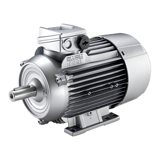
Page 33: Description
Description Area of application The synchronous machines of this series are used as industrial drives for textile machines. They are designed for converter operation. Do not connect these SIMOTICS A machines directly to the line supply. These machines are characterized by their high power density, ruggedness, long lifetime and overall reliability. -
Page 34: Rating Plate
Description 4.2 Rating plates 4.2.1 Rating plate Data on the rating plate Item Description Item Description General data Electrical data Type of machine Electrical data Machine type Rated voltage V Serial number (incl. date of manufacture Winding connections YY.MM) Standards Frequency Hz Additional details (optional) Rated power kW Customer data (optional) -
Page 35: Installation
Description 4.3 Installation Installation 4.3.1 Machine version synchronous machines Machines in this series are customized, permanent-magnet three-phase synchronous machines. They are designed with IP55 or IP54 degree of protection. Machines without shaft sealing rings are in degree of protection IP54. Refer to the rating plate data for the degree of protection. 4.3.2 Regulations for synchronous motors Regulations for synchronous motors... -
Page 36: Machines With A Fan
Description 4.3 Installation 4.3.3.1 Machines with a fan Self-ventilation (standard): Cooling method IC 411 according to EN / IEC 60034-6 Located at the ND end of the stator housing is an air intake cowl that guides the external air on its way to the motor. The external air is drawn in through openings in the air intake cowl and flows axially across the outer cooling ribs of the motor frame. -
Page 37: Bearings Of Synchronous Machines
Description 4.3 Installation Surface cooling by relative movement of cooling air: Cooling method IC 418 according to EN / IEC 60034-6 IC418 IC4A1A8 Figure 4-2 IC418 4.3.4 Bearings of synchronous machines In order to support the machine shaft and maintain its position in the non-moving part of the machine, only 2 rolling bearings are used. - Page 38 Description 4.3 Installation Table 4-2 Type of construction Basic type of construc‐ Diagram Other methods of in‐ Diagram tion code stallation IM B3 (IM 1001) IM V5 (IM 1011) IM V6 (IM 1031) IM B6 (IM 1051) IM B7 (IM 1061) IM B8 (IM 1071) Basic type of construc‐...
-
Page 39: Degree Of Protection
Description 4.3 Installation Basic type of construc‐ Diagram tion code IM B35 (IM 2001) IM B34 (IM 2101) 4.3.7 Degree of protection The machine has a type of protection as stamped on the rating plate, and can be installed in dusty or humid environments. 4.3.8 Environmental conditions Limit values for the standard version... -
Page 40: Documents For Geared Motors And Mounted Gearing
4.3.10 Documents for geared motors and mounted gearing For machines with gearboxes, comply with the instructions provided in the operating instructions: SIMOGEAR gearbox (BA 2030) (https://support.industry.siemens.com/cs/ww/en/ view/60666158) Note Further documents Observe all of the other documents provided with this machine. -
Page 41: Preparing For Use
The drive systems are put together on an individual basis. When receiving the delivery, immediately check whether the scope of delivery matches the accompanying documents. SIEMENS will not accept any claims for missing or incorrect items submitted at a later date. • Report any apparent transport damage to the delivery agent immediately. -
Page 42: Transport And Storage
Preparing for use 5.4 Transport and storage Transport and storage 5.4.1 Reference to chapter Safety instructions Comply with the following when carrying out any work on the machine: • Comply with the general safety instructions (Page 27). • Comply with the applicable national and sector-specific regulations. •... -
Page 43: Transporting Certain Frame Sizes
Preparing for use 5.4 Transport and storage 5.4.2 Transporting certain frame sizes Note When lifting the machines for transport, only lift them in a position that corresponds to their basic construction type. 5.4.3 Types of construction on the rating plate The type of construction of the machine is stated on the rating plate. If any transport locks are in place, remove them before commissioning. - Page 44 Preparing for use 5.4 Transport and storage equipment from sinking into the ground. Do not impede air circulation under the stored items. Covers or tarpaulins used to protect the equipment against the weather must not come into contact with the surfaces of the equipment. Use wooden spacer elements to ensure that air can circulate freely around the equipment.
-
Page 45: Commissioning After Storage
Preparing for use 5.4 Transport and storage NOTICE Storage The motor can be damaged if you use it or store it unprotected outdoors. • Protect the motor against intensive solar radiation, rain, snow, ice and dust. Use a superstructure or additional cover, for example. •... -
Page 46: Regreasing Rolling Bearings After Storage Periods Of Up To Two Years
Preparing for use 5.5 Ensure adequate cooling 5.4.5.3 Regreasing rolling bearings after storage periods of up to two years • For machines with regreasing systems, briefly lubricate both bearings after commissioning with the machine running as a precautionary measure. • Grease type, grease quantity and relubrication intervals for the regreasing system are stamped on the rating plate attached to the machine. - Page 47 Preparing for use 5.5 Ensure adequate cooling Table 5-1 Air guidance Incorrect Correct Minimum dimension "x" for the distance between neighboring modules and the air intake of the machine Table 5-2 Minimum dimension "x" for the distance between adjacent modules and the air intake of the machine Frame size 80 ...
-
Page 48: Noise Emissions
Preparing for use 5.7 Rotational speed limit values Frame size Noise emissions Noise emissions During operation, the machine's noise emission levels can exceed those permitted at the workplace, which can cause hearing damage. • Ensure that nobody is in the area of increased noise emissions during machine operation. •... -
Page 49: System-Inherent Frequencies
Preparing for use 5.9 Electromagnetic compatibility Machine damage due to excessively high speeds Excessive rotational speed can lead to serious damage to the machine. This can result in death, serious injury or material damage. • Avoid operation above the permissible speed by using the appropriate control function. •... -
Page 50: Converter Operation
Preparing for use 5.10 Converter operation Immunity to interference The machines fulfill the requirements of interference immunity in conformity with EN / IEC 61000-6-2. For machines with integrated sensors, e.g. PTC thermistors, the operating company must ensure sufficient interference immunity by selecting a suitable sensor signal cable (possibly with shielding, connected in the same way as the machine feeder cable) and a suitable evaluation unit. -
Page 51: Reducing Bearing Currents
Preparing for use 5.10 Converter operation NOTICE Material damage caused by an excessively high supply voltage The insulation system will be damaged if the supply voltage is too high for the insulation system. This can completely destroy the machine. • Comply with the peak voltages as laid down in the guidelines above. 5.10.3 Reducing bearing currents To prevent damage due to bearing currents, you must carefully assess the complete system, i.e. -
Page 52: Insulated Bearings For Converter Operation
Preparing for use 5.10 Converter operation • Use the common-mode filter (damping cores) at the converter output. The SIEMENS sales partner is responsible for selecting and dimensioning. • Limit the rise in voltage by using output filters. Output filters dampen the harmonic content in the output voltage. -
Page 53: Speed Limits For Converter Operation
Preparing for use 5.10 Converter operation ① ④ Driven machine Insulated bearings ② ⑤ Motor Insulated tachometer fitting ③ ⑥ Coupling Insulated coupling Figure 5-2 Schematic representation of a tandem drive NOTICE Bearing damage Bearing currents can flow if the coupling between the motors of the tandem drive is not insulated. - Page 54 Preparing for use 5.10 Converter operation 1FU9 Operating Instructions, 10/2023, A5E46712792A...
-
Page 55: Assembly
Assembly Reference to chapter Safety instructions Comply with the following when carrying out any work on the machine: • Comply with the general safety instructions (Page 27). • Comply with the applicable national and sector-specific regulations. • When using the motor within the European Union, comply with the specifications laid down in EN 50110‑1 regarding safe operation of electrical equipment. -
Page 56: Preparing For Installation
Assembly 6.3 Preparing for installation Material damage caused by improper handling Mounting parts such as temperature sensors or speed sensors are attached to the machine and could be ripped off or destroyed as a result of improper handling. This could lead to machine malfunctions, extending even to total loss of the machine. -
Page 57: Insulation Resistance
Assembly 6.3 Preparing for installation NOTICE Damage to the motor To avoid material damage, before commissioning, check whether the correct direction of rotation of the machine has been set on the customer side, e.g. by decoupling from the driven load. Damage to mounted parts and components as a result of high temperatures The motor components get very hot during operation. -
Page 58: Checking The Insulation Resistance And Polarization Index Of The Winding
Assembly 6.3 Preparing for installation 6.3.3.2 Checking the insulation resistance and polarization index of the winding WARNING Hazardous voltage at the terminals Hazardous voltages are sometimes present at the terminals during and immediately after measurement of the insulation resistance or polarization index of the winding. Contact with these can result in death, serious injury or material damage. - Page 59 Assembly 6.3 Preparing for installation Limit values for the winding insulation resistance The following table specifies the measuring voltage and limit values for the insulation resistance. These values correspond to the recommendations of IEC 60034-27-4 and IEEE 43‑2000. Table 6-1 Insulation resistance of the winding at 40 °C meas MΩ...
- Page 60 Assembly 6.3 Preparing for installation For a winding temperature of approx. 25° C, the minimum insulation resistances are 20 MΩ (U ≤ 1000 V) or 300 MΩ (U > 1000 V). The values apply for the complete winding to ground. Twice the minimum values apply to the measurement of individual assemblies. •...
-
Page 61: Installing The Machine
Assembly 6.5 Alignment and fastening Installing the machine 6.4.1 Preparing the assembly area 1. Prepare a suitable assembly area (e.g. assembly stands). Make sure that the assembly area has sufficient clearance from the floor for the DE shaft end. The necessary data is provided in the machine dimension drawing. - Page 62 Assembly 6.5 Alignment and fastening • Avoid mounting-related resonance effects with the rotational frequency. • Note any unusual noise when the rotor is manually turned. • Check the direction of rotation with the motor uncoupled. • Avoid rigid couplings. • Repair any damage to the paint, this must be done immediately and correctly. The following measures are required in order to compensate any radial offset at the coupling and to horizontally adjust the electrical machine with respect to the driven load: •...
-
Page 63: Flatness Of The Supporting Surfaces For Conventional Motors
Assembly 6.6 Installing the machine 6.5.1 Flatness of the supporting surfaces for conventional motors Shaft height Flatness [mm] ≤ 132 0.10 0.15 ≥ 180 0.20 6.5.2 Machine frame mounting feet (special design) Please note that when the terminal box is mounted at the NDE (option H08), dimension C can deviate from EN 50347. -
Page 64: Horizontal Types Of Construction With Mounting Feet
Assembly 6.6 Installing the machine 6.6.2.2 Horizontal types of construction with mounting feet 1. Refer to any instructions for aligning the driven machine and those of the coupling manufacturer. 2. Align the machines with coupling output to the driven machine in such a manner that the center lines of the shafts are parallel with no offset. -
Page 65: Vertical Types Of Construction With Flange
Assembly 6.6 Installing the machine 6.6.2.4 Vertical types of construction with flange The standard flange is provided with a centering. The choice of fit for the mating flange on the driven machine is the system manufacturer's or the plant operator's responsibility. If the machine is not fitted with a standard flange, align the machine to suit the driven machine. -
Page 66: Mounting The Drive Output Elements
Assembly 6.6 Installing the machine 6.6.5 Mounting the drive output elements The rotor is dynamically balanced. For shaft extensions with feather keys, the type of balancing is specified using the following coding on the face of the drive end of the shaft extension and on the rating plate: •... - Page 67 Assembly 6.6 Installing the machine Pulling on drive output elements • Requirements: – The coupling and/or the drive output element must be appropriately dimensioned for the operating case at hand. – Observe the coupling manufacturer's instructions. – Make sure that the balancing type of the drive output element correctly matches the type of balance of the rotor.
- Page 68 Assembly 6.6 Installing the machine Only transfer radial or axial forces specified in the catalog to the machine bearings via the shaft extension. You can obtain the permissible values for axial and radial forces by contacting the Service Center (Page 12) or by referring to the machine catalog. Shaft extensions with feather key The feather key data for the shaft and drive output element must match and indicate the correct type of balancing.
-
Page 69: Electrical Connection
Electrical connection Reference to chapter Safety instructions Comply with the following when carrying out any work on the machine: • Comply with the general safety instructions (Page 27). • Comply with the applicable national and sector-specific regulations. • When using the motor within the European Union, comply with the specifications laid down in EN 50110‑1 regarding safe operation of electrical equipment. -
Page 70: Connecting The Machine
Electrical connection 7.2 Connecting the machine • Electronic modules should not be brought into contact with electrically insulating materials, such as: – Plastic film – Plastic parts – Insulating table supports – Clothing made of synthetic fibers • Always place the modules on conductive and grounded surfaces. •... -
Page 71: Selecting Cables
Electrical connection 7.2 Connecting the machine • The temperature increases if voltage, frequency, waveform and symmetry deviate from their rated values. • Carefully comply with the information provided in EN / IEC 60034-1 (VDE 0530-1) regarding operation at the limits of A and B zones, especially in respect of temperature increase and deviation of the operating data from the rated data stamped on the rating plate. -
Page 72: Terminal Box
Electrical connection 7.2 Connecting the machine 7.2.2 Terminal box DANGER Hazardous voltage Electric motors have high voltages. When incorrectly handled, this can result in death or severe injury. Switch off the machine so that it is in a no-voltage condition before you open the terminal box. NOTICE Damage to the terminal box If you incorrectly carry out work on or in the terminal box, this can result in material damage. -
Page 73: Cable Entry
Electrical connection 7.2 Connecting the machine 7.2.2.3 Cable entry Assembly and laying of cables Screw the screw-type connection into the housing or fasten with a nut. Note The screw-type connections must have been matched to the connecting cables used (diameter armoring, braid, shield). For the screw-type connections, comply or exceed the requirements relating to IP degree of protection (water and dust) - as well as the temperature range in operation stamped on the rating plate. -
Page 74: Connecting Protruding Cables
Electrical connection 7.2 Connecting the machine 7.2.2.6 Connecting protruding cables In the case of connection cables brought out of the machine, no terminal board is installed on the terminal base of the machine housing. The connection cables are directly connected to stator winding terminals at the factory. -
Page 75: Cable Glands
Electrical connection 7.2 Connecting the machine WARNING Dangerous voltage when the rotor rotates There are dangerous voltages at the terminals while the machine rotor rotates and immediately afterwards. You must observe the following safety instructions to prevent death, injury or material damage: •... -
Page 76: Mounting Position Of Sheet Metal Nuts In Screw-Type Connections
Electrical connection 7.3 Tightening torques 7.2.3.1 Mounting position of sheet metal nuts in screw-type connections ② O ring ③ Mounting position of metal-sheet nuts Cable glands with connecting thread in the terminal box (EN 50262) ② O ring Tightening torques Note the information in Chapter Tightening torques (Page 133). 7.3.1 Cable entries, sealing plugs and thread adapters Note the following when mounting:... -
Page 77: Connecting The Grounding Conductor
Electrical connection 7.4 Connecting the grounding conductor Connecting the grounding conductor 7.4.1 General information on connecting the grounding conductor The machine's grounding conductor cross-section must comply with EN / IEC 60034-1. Please also observe installation regulations such as those specified in EN / IEC 60204-1. Basically, there are two ways of connecting a grounding conductor to the machine. •... -
Page 78: Size Of Grounding Conductor Screw
Electrical connection 7.4 Connecting the grounding conductor Internal ground terminal Comply with the following instructions when connecting up: • Ensure that the connecting surface is bare and is protected against corrosion using a suitable substance, e.g. acid-free Vaseline. • Arrange the spring lock washer under the screw head. •... -
Page 79: Connecting The Temperature Sensor
Electrical connection 7.5 Connecting the temperature sensor Connecting the temperature sensor WARNING Hazard due to electric shock The installation of the temperature sensors for the winding monitoring with respect to the winding is implemented according to the requirements for basic insulation. The temperature sensor connections are located in terminal boxes that are safe to touch and have no protective separation. -
Page 80: Conductor Connection
Electrical connection 7.6 Conductor connection Conductor connection 7.6.1 General information on conductor connection Cross-sections that can be connected depending on the size of the terminal (possibly reduced due to size of cable entries) Table 7-5 Max. conductor connection Shaft height Max. connectable conductor cross-section [mm²] 63 ... -
Page 81: Type Of Conductor Connection
Electrical connection 7.6 Conductor connection 7.6.2 Type of conductor connection Terminal board Conductor cross-sec‐ tion mm² Connection with cable lug DIN 46 234 Bend down the cable lug for the ... 25 connection. Connection of an individual conduc‐ tor with terminal clamp ... -
Page 82: Connecting Aluminum Conductors
Electrical connection 7.7 Connecting converters 7.6.3 Connecting aluminum conductors If you are using aluminum conductors, then comply with the following: • Use only cable lugs that are suitable for connecting aluminum conductors. • Immediately before inserting the aluminum conductor, remove the oxide layer from the contact areas on the conductor and/or the mating piece. -
Page 83: Final Checks
Electrical connection 7.8 Final checks Depending on the step height, the voltage rise times for the individual voltage steps in the line-to-ground voltage at the motor end of the cable must not fall below the following values. Table 7-7 Rise times as a function of voltage level Step height Minimum rise time t 1050... - Page 84 Electrical connection 7.8 Final checks 1FU9 Operating Instructions, 10/2023, A5E46712792A...
-
Page 85: Commissioning
Commissioning Reference to chapter Safety instructions Comply with the following when carrying out any work on the machine: • Comply with the general safety instructions (Page 27). • Comply with the applicable national and sector-specific regulations. • When using the motor within the European Union, comply with the specifications laid down in EN 50110‑1 regarding safe operation of electrical equipment. -
Page 86: Mechanical Checks
Commissioning 8.2 Measures before commissioning • The operating conditions match the data provided in accordance with the technical documentation, such as degree of protection, ambient temperature, etc. • Moving parts, for example the coupling, move freely. • All touch protection measures for both moving and live parts have been implemented. •... -
Page 87: Insulation Resistance And Polarization Index
Commissioning 8.2 Measures before commissioning Converter operation • If the motor design requires connection to a specific converter type, carefully check the supplementary data on the rating plate/supplementary plate. • Ensure that the converter is correctly parameterized. Depending on the design, you will find some parameterization data on the rating plate of the machine. -
Page 88: Commissioning The Separately Driven Fan
Commissioning 8.2 Measures before commissioning 8.2.5 Commissioning the separately driven fan The separately driven fan ensures that the main machine is cooled irrespective of the main machine speed or direction of rotation. The separately driven fan is only suitable for one direction of rotation. -
Page 89: Further Documents
Commissioning 8.2 Measures before commissioning 8.2.6 Further documents Note Further documents Observe all of the other documents provided with this machine. 8.2.7 Setpoint values for monitoring the bearing temperature Prior to commissioning If the machine is equipped with bearing thermometers, set the temperature value for disconnection on the monitoring equipment before the first machine run. -
Page 90: Dangerous Voltage When The Rotor Rotates
Commissioning 8.3 Switching on 8.2.8 Dangerous voltage when the rotor rotates WARNING Dangerous voltage when the rotor rotates There are dangerous voltages at the terminals while the machine rotor rotates and immediately afterwards. You must observe the following safety instructions to prevent death, injury or material damage: •... - Page 91 Commissioning 8.3 Switching on 4. During the test run, check and document the following: – Check whether it is running smoothly. – Document the voltage, current and power values. As far as possible, document the corresponding values of the driven machine. –...
- Page 92 Commissioning 8.3 Switching on 1FU9 Operating Instructions, 10/2023, A5E46712792A...
-
Page 93: Operation
Operation Reference to chapter Safety instructions Comply with the following when carrying out any work on the machine: • Comply with the general safety instructions (Page 27). • Comply with the applicable national and sector-specific regulations. • When using the motor within the European Union, comply with the specifications laid down in EN 50110‑1 regarding safe operation of electrical equipment. -
Page 94: Safety Instructions In Operation - Parts That Are Not Covered, And That Are Under Voltage (Live Parts)
Operation 9.2 Safety instructions for operation 9.2.2 Safety instructions in operation - parts that are not covered, and that are under voltage (live parts) Danger as a result of stationary parts under voltage (live parts) Live parts represent a hazard. Touch protection against active (live) parts is no longer guaranteed if covers are removed. - Page 95 Operation 9.2 Safety instructions for operation Hazardous substances Chemical substances required for the setup, operation and maintenance of machines can present a health risk. Poisoning, skin damage, cauterization of the respiratory tract, and other health damage may result. • Carefully comply with the information in these operating instructions and the product information supplied by the manufacturer.
-
Page 96: Safety Instructions Relating To Ventilation And Cooling
Operation 9.2 Safety instructions for operation WARNING Faults in operation Changes with respect to normal operation indicate that there is an impaired function. This can cause faults which can result in eventual or immediate death, severe injury or material damage. For instance, watch out for the following signs that could indicate a malfunction: •... -
Page 97: Safety Instructions When Operating Machines With Fan
Operation 9.2 Safety instructions for operation 9.2.3.2 Safety instructions when operating machines with fan CAUTION Risk of injury when touching the fan There is a risk of injury at machines equipped with a fan cover (e.g. on machines in the textile industry), as the fan is not completely touch protected. -
Page 98: Switching On The Machine
Operation 9.6 Stoppages Switching on the machine 1. Operate the machine without a load and check that it is running smoothly. 2. If it runs perfectly, connect a load. NOTICE Thermal overload In addition to the load torque, the ramp-up (accelerating) time is essentially influenced by the moment of inertia to be accelerated. - Page 99 Operation 9.6 Stoppages Longer non-operational periods Note • For longer non-operational periods (> 1 month), either operate the machine or at least turn the rotor regularly, approximately once per month. • Please refer to the section "Switching on" before switching on to recommission the motor. •...
-
Page 100: Avoidance Of Damage To Rolling Bearings During Stoppages
Operation 9.7 faults 9.6.1 Avoidance of damage to rolling bearings during stoppages Extended stoppages at the identical or almost identical resting position of the rotor in the rolling bearings can result in damage, such as brinelling or corrosion. • During stoppages, regularly start up the machine for a brief period once a month. As a minimum, turn the rotor several times. -
Page 101: Electrical Faults
Operation 9.7 faults 9.7.2 Electrical faults Note If you are operating the motor with a converter, the operating instructions of the converter must also be complied with if electrical faults occur. Table 9-1 Electrical faults ↓ Motor fails to start ↓... -
Page 102: Mechanical Faults
Operation 9.7 faults 9.7.3 Mechanical faults Table 9-2 Mechanical faults ↓ Grinding noise ↓ Radial vibrations ↓ Axial vibrations Possible causes of faults Remedial measures Rotating parts grind Establish the cause and realign the parts. ... -
Page 103: Faults At The External Fan
Operation 9.8 Deactivating Too much grease in bearing Remove surplus grease. Wrong grease in the bearing Use the correct grease. Friction marks on raceway Replace the bearing. Brinelling or scoring Replace the bearing. Avoid any vibration at standstill 9.7.5 Faults at the external fan The following table shows the possible causes of and remedial measures for faults on forced-... - Page 104 Operation 9.8 Deactivating 1FU9 Operating Instructions, 10/2023, A5E46712792A...
-
Page 105: Maintenance
Maintenance 10.1 General Through careful and regular maintenance, inspections and overhauls, you can detect faults at an early stage and resolve them. This means that you can avoid consequential damage. Operating situations and characteristics can vary widely. For this reason, only general maintenance intervals can be specified here. -
Page 106: Preparation And Notes
Maintenance 10.3 Preparation and notes 10.3 Preparation and notes 10.3.1 Danger when openly storing rotors WARNING Danger when openly storing rotors The rotors of the synchronous machines contain permanent magnets with high magnetic flux densities and strong attraction forces to ferromagnetic bodies. You must observe the following safety instructions to prevent death, injury or material damage: •... -
Page 107: Inspection And Maintenance
Maintenance 10.4 Inspection and maintenance 10.4 Inspection and maintenance 10.4.1 Safety instructions for inspection and maintenance WARNING Rotating and live parts Electric machines contain live and rotating parts. Fatal or serious injuries and substantial material damage can occur if maintenance work is performed on the machine when it is not stopped or not de-energized. -
Page 108: Inspections In The Event Of Faults
Maintenance 10.4 Inspection and maintenance NOTICE Machine damage caused by foreign bodies Foreign bodies such as dirt, tools or loose components, such as screws etc., can be left by accident inside the machine after maintenance is performed. These can cause short circuits, reduce the performance of the cooling system or increase noise in operation. -
Page 109: General Inspection
Maintenance 10.4 Inspection and maintenance Checking When the At stand‐ motor is still running The smooth running characteristics and machine running noise have not de‐ teriorated. The foundation has no cracks or indentations. (*) (*) You can perform these checks while the motor is running or at a standstill. Additional tests may also be required according to the system-specific conditions. -
Page 110: Assessing The Rolling Bearings
Maintenance 10.4 Inspection and maintenance NOTICE Machine damage When carrying out the inspection, if you detect any impermissible deviations from the normal state, you must rectify them immediately. They may otherwise cause damage to the machine. 10.4.5 Assessing the rolling bearings To assess the rolling bearings, it is generally not necessary to dismantle the machines. -
Page 111: Re-Greasing
Maintenance 10.4 Inspection and maintenance Operating situations and characteristics can vary widely. For this reason, only general maintenance intervals are specified here. Maintenance intervals should therefore be scheduled to suit the local conditions (dirt, starting frequency, load, etc.). Table 10-3 Operating period intervals Measures Operating period intervals Intervals... -
Page 112: Cleaning
Maintenance 10.4 Inspection and maintenance The bearing temperature can rise significantly at first, and then drops to the normal value again when the excess grease is displaced out of the bearing. WARNING Rotor can fall out If the machine is in a vertical position, the rotor can fall out while work is being performed on the locating bearing. -
Page 113: Drain Condensate
Maintenance 10.4 Inspection and maintenance 10.4.10 Drain condensate If there are condensation drain holes present, open these at regular intervals, depending on climatic conditions. WARNING Hazardous voltage The winding can be damaged if objects are introduced into the condensation holes (optional). This can lead to death, serious injury or material damage. -
Page 114: Servicing The Separately Driven Fan
Maintenance 10.5 Corrective maintenance 10.4.12 Servicing the separately driven fan WARNING Injury caused by rotating parts or live (under voltage) parts Live electrical parts are dangerous. Contact with them can cause death, serious injury or material damage. • Before performing any maintenance work on the separately driven fan, disconnect it from the mains, particularly before opening the terminal box. -
Page 115: Rolling Bearings
Maintenance 10.5 Corrective maintenance Note Before commencing removal, you should mark how each of the fastening elements has been assigned, as well as how internal connections are arranged. This simplifies subsequent reassembly. Avoid damaging the windings protruding out of the stator enclosure when assembling the end shield. -
Page 116: Bearing Bushes
Maintenance 10.5 Corrective maintenance • Do not reuse bearings that have been removed. • Remove the dirty spent grease from the bearing shield. • Replace the existing grease with new grease. • Replace the shaft seals when the bearings are replaced. •... -
Page 117: Installing Rolling Bearings
Maintenance 10.5 Corrective maintenance When fitting the bearing cartridges, observe the specified screw tightening torques. 10.5.2.2 Installing rolling bearings • Extreme caution and attention to cleanliness are crucial when installing rolling bearings. Observe the correct assembly sequence of the components. • Attach all components with the specified tightening torques (Page 133). Note For further information about mounting the rolling bearing, please refer to the catalog or the information provided by the rolling bearing manufacturer. -
Page 118: Shaft Sealing, Mounting Dimensions And Alignment
Maintenance 10.5 Corrective maintenance Sealing the bearings Note the following details: • Shaft sealing rings are used to seal machines at the rotor shaft. – For V rings, comply with the assembly dimension. • Use the specified bearings. • Ensure that the bearing sealing disks are in the correct position. •... -
Page 119: Fan
Maintenance 10.5 Corrective maintenance 10.5.4 NOTICE Destruction of the fan Material damage can occur by forcefully removing the fan from the shaft. Take care not to damage the snapping mechanisms on fans that are equipped with these. Plastic fan • Correctly expose the breakout openings provided in the fan plate. •... -
Page 120: Mounting Fans
• Check the tightening torques of all screws, as well as those of screws that have not been released. 10.5.8 Optional add-on units Note Further documents Observe all of the other documents provided with this machine. You can find additional operating instructions here: Siemens Industry Online Support on the Web (Page 12) 1FU9 Operating Instructions, 10/2023, A5E46712792A... -
Page 121: Maintain The Brake
Maintenance 10.5 Corrective maintenance 10.5.8.1 Maintain the brake Wear of the spring-operated brake The friction lining and the mechanical components of the brake are subject to wear due to their inherent function. For safe and fault-free operation, the brake must be regularly checked and adjusted, and if necessary, replaced. - Page 122 For operational braking, the maintenance intervals depend on the loading on the brake in the application. Take all causes of wear into account when calculating the maintenance intervals. Siemens recommends a regular inspection at fixed time intervals for brakes that are subject to low loads, e.g. holding brakes with an emergency stop.
- Page 123 Maintenance 10.5 Corrective maintenance Figure 10-1 Setting dimension for air gap Procedure 1. Remove the fan cover. 2. Loosen the fastening screws of the brake. 3. Screw the sleeve screws further into the solenoid using an open-ended spanner. 4. Tighten the fastening screws of the brake. 5.
- Page 124 Maintenance 10.5 Corrective maintenance You have now set the air gap. Table 10-7 Air gap values Brake type Nominal air Maximum air gap for Reference gage Standard excita‐ Overexcitation tion Lmax. (+0.1 / -0.05) Lmax. L4/1,4 0.65 L4/2 L4/3 0.55 L4/5 L8/3, L8/4 L8/5, L8/6,3 0.55 L8/10...
- Page 125 Maintenance 10.5 Corrective maintenance Table 10-8 Tightening torque for the brake screw Brake type Thread size Tightening torque Siemens Brake supplier INTORQ BA BFK458 (06E) 3 x M4 INTORQ BA BFK458 (08E) 3 x M5 INTORQ BA BFK458 (10E) 3 x M6 INTORQ BA BFK458 (12E) 3 x M6 L60, L80 INTORQ BA BFK458 (14E), IN‐ 3 x M8 TORQ BA BFK458 (16E) L150 INTORQ BA BFK458 (18E) 6 x M8 L260, L400 INTORQ BA BFK458 (20E), IN‐ 6 x M10 TORQ BA BFK458 (25E)
-
Page 126: O-Ring Seal
Maintenance 10.5 Corrective maintenance 9. Calculate the gap between the solenoid and the armature disk as follows: Gap = rotor thickness + s - head height. 10.Unscrew the sleeve screws evenly until the calculated gap between the solenoid and the armature disk is reached. 11.Mount the new rotor and solenoid. Set the air gap of the brake, see Adjusting the air gap (Page 120). - Page 127 Maintenance 10.5 Corrective maintenance • Terminal box sealing • etc. 1FU9 Operating Instructions, 10/2023, A5E46712792A...
- Page 128 Maintenance 10.5 Corrective maintenance 1FU9 Operating Instructions, 10/2023, A5E46712792A...
-
Page 129: Spare Parts
Spare parts In addition to the exact part designation, please specify the machine type and the serial number of the machine in all orders for spare parts and repair parts. Ensure that the part designation is the same as that in the parts list, and make sure you also use the associated part number. When spare and repair parts are ordered, the following details must be provided: •Designation and part number •Machine type and serial number... - Page 130 Spare parts 1FU9 Operating Instructions, 10/2023, A5E46712792A...
-
Page 131: Disposal
Disposal 12.1 Introduction Protecting the environment and preserving its resources are corporate goals of the highest priority for us. Our worldwide environmental management system to ISO 14001 ensures compliance with legislation and sets high standards in this regard. Environmentally friendly design, technical safety and health protection are always firm goals even at the product development stage. -
Page 132: Preparing For Disassembly
Disposal 12.7 Disposal of components Based on the currently available information, we assume that this substance does not represent any risk when correctly used, including its disposal. 12.5 Preparing for disassembly Disassembly of the machine must be carried out and/or supervised by qualified personnel with appropriate expert knowledge. - Page 133 Disposal 12.7 Disposal of components • Insulating materials • Cables and wires • Electronic waste Process materials and chemicals Sort the process materials and chemicals for recycling according to whether they are for example: • Oil • Grease • Cleaning substances and solvents •...
- Page 134 Disposal 12.7 Disposal of components WARNING Danger when openly storing rotors The rotors of the synchronous machines contain permanent magnets with high magnetic flux densities and strong attraction forces to ferromagnetic bodies. You must observe the following safety instructions to prevent death, injury or material damage: •...
-
Page 135: Technical Data
Technical data Tightening torques A.1.1 Tightening torques for screw and bolt connections Bolt locking devices • When assembling, refit nuts or bolts that are mounted together with locking, resilient, and/or force-distributing elements with identical, fully-functional elements. Always renew keyed elements. •... -
Page 136: Terminal Board And Grounding
Technical data A.1 Tightening torques A.1.2 Terminal board and grounding Table A-2 Tightening torques for electrical connections on the terminal board and grounding Thread ∅ M3.5 min. max. A.1.3 Terminal boxes, end shields, grounding conductors, sheet metal fan covers If no other tightening torques are specified, then the values in the following table apply. Table A-3 Tightening torques for screws on the terminal box, end shields, screw-type grounding conductor connections Thread ∅... -
Page 137: Additional Connecting Terminals For Monitoring Equipment
Technical data A.1 Tightening torques You should refer to the table in order to find the correct tightening torque for any metal and plastic cable glands that are to be mounted directly on the machine, as well as for any other screw-type connections (such as adapters). - Page 138 Technical data A.1 Tightening torques 1FU9 Operating Instructions, 10/2023, A5E46712792A...
- Page 140 More information Siemens: Industry Online Support (Service and Support): www.siemens.com/online-support IndustryMall: www.siemens.com/industrymall Germany...
Need help?
Do you have a question about the SIMOTICS A 1FU9 and is the answer not in the manual?
Questions and answers