
Related Manuals for Yamaha MT-10 SP 2016


Summary of Contents for Yamaha MT-10 SP 2016
- Page 1 Read this manual carefully before operating this vehicle. OWNER’S MANUAL MTN1000D BW8-28199-E0 0...
- Page 2 EAU70091 Read this manual carefully before operating this vehicle. This manual should stay with this vehicle if it is sold. YAMAHA MOTOR ELECTRONICS CO., LTD. 1450-6, Mori, Mori-machi, Shuchi-gun, Shizuoka-ken, 437-0292 Japan DECLARATION of CONFORMITY Product: IMMOBILIZER Model: 1MC-00 Supplied by...
- Page 3 EAU10103 Welcome to the Yamaha world of motorcycling! As the owner of the MTN1000D, you are benefiting from Yamaha’s vast experience and newest technology regarding the design and manufacture of high-quality products, which have earned Yamaha a reputation for dependability.
- Page 4 Important manual information EAU10134 Particularly important information is distinguished in this manual by the following notations: This is the safety alert symbol. It is used to alert you to potential personal injury hazards. Obey all safety messages that follow this symbol to avoid possible injury or death.
- Page 5 Important manual information EAU10201 MTN1000D OWNER’S MANUAL ©2016 by Yamaha Motor Co., Ltd. 1st edition, October 2016 All rights reserved. Any reprinting or unauthorized use without the written permission of Yamaha Motor Co., Ltd. is expressly prohibited. Printed in Japan.
-
Page 6: Table Of Contents
Ignition circuit cut-off system..4-38 Tires..........7-18 Special features ....... 3-1 Cast wheels ......... 7-20 For your safety – pre-operation YRC (Yamaha Ride Control) ..3-1 Adjusting the clutch lever free checks ..........5-1 Glossary ......... 3-3 play........... 7-21 Cruise control system ..... 3-3... - Page 7 Table of contents Lubricating the swingarm pivots......... 7-29 Checking the front fork ....7-29 Checking the steering....7-30 Checking the wheel bearings ..7-30 Battery .......... 7-30 Replacing the fuses ...... 7-32 Vehicle lights ........ 7-35 Supporting the motorcycle.... 7-35 Troubleshooting......
-
Page 8: Safety Information
Safety information EAU1028B Take a training course. Beginners • Use extra caution when you are should receive training from a cer- approaching passing tified instructor. Contact an autho- through intersections, since in- Be a Responsible Owner rized motorcycle dealer to find out tersections are the most likely As the vehicle’s owner, you are respon- about the training courses nearest... - Page 9 Safety information tice riding your motorcycle with both hands and keep both control levers, footrests, or wheels where there is no traffic until you feet on the passenger footrests. and cause injury or an accident. have become thoroughly famil- Never carry a passenger unless Always wear protective clothing iar with the motorcycle and all of...
- Page 10 Yamaha accessories, which are avail- to minimize imbalance or instabili- of the motorcycle is changed. To avoid able only from a Yamaha dealer, have the possibility of an accident, use ex- been designed, tested, and approved ...
- Page 11 Yamaha, even if sold and limit suspension travel, steering not recommended. installed by a Yamaha dealer.
- Page 12 Safety information Check that the fuel cock (if equipped) is in the “OFF” position and that there are no fuel leaks. Point the front wheel straight ahead on the trailer or in the truck bed, and choke it in a rail to pre- vent movement.
-
Page 13: Description
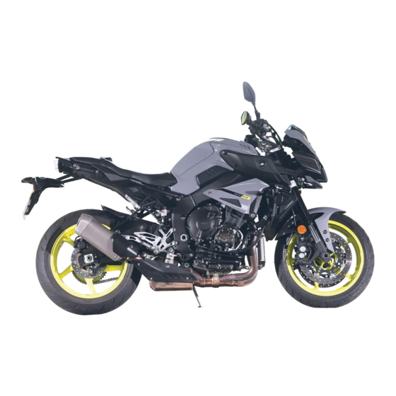
Description EAU10411 Left view 2, 3 1. Headlight (page 7-35) 9. Fuse box (page 7-32) 2. ERS coupler (page 4-33) 3. Spring preload adjusting bolt (page 4-33) 4. Battery (page 7-30) 5. Spring preload adjusting ring (page 4-34) 6. Shift pedal (page 4-27) 7. -
Page 14: Right View
Description EAU10421 Right view 1, 2 5, 6 1. Main fuse (page 7-32) 9. Coolant drain bolt (page 7-14) 2. ABS motor fuse (page 7-32) 10.Brake pedal (page 4-28) 3. Owner’s tool kit (page 7-2) 11.Rear brake fluid reservoir (page 7-23) 4. -
Page 15: Controls And Instruments
Description EAU10431 Controls and instruments 1. Clutch lever (page 4-27) 9. Brake lever (page 4-27) 2. Left handlebar switches (page 4-3) 3. Auxiliary DC jack (page 4-36) 4. Main switch/steering lock (page 4-2) 5. Instrument panel (page 4-5, 4-8) 6. Front brake fluid reservoir (page 7-23) 7. -
Page 16: Special Features
YRC (Yamaha Ride Control) oughly familiar with the way the mo- WARNING torcycle handles with various YRC Yamaha Ride Control is a system that The traction control system is not a incorporates numerous sensors and settings before attempting more ad-... - Page 17 SCU which makes in- check the vehicle as soon as possible. Resetting the traction control sys- dependent adjustments of both the 4. Have a Yamaha dealer check the front and rear suspension’s compres- vehicle and turn off the “ ” warn-...
-
Page 18: Glossary
TCS - Traction Control System 2. Cruise control system indicator light “ ” trol system may result in loss of YRC - Yamaha Ride Control control, which could lead to an accident. Do not activate the cruise control system in heavy... - Page 19 Special features switch “ ” located on the left han- new cruising speed by pushing the Disengage the clutch. dlebar. The cruise control system “SET–” side of the setting switch. If you Push the power switch to turn off the indicator light “...
- Page 20 Special features set cruising speed. You will not be able for 4 seconds, and then go off. the set cruising speed. If this oc- to use the resume function until a new When not traveling with a set cruising curs, the setting switch cannot be cruising speed has been set.
-
Page 21: Instrument And Control Functions
Do not place any key close to a Yamaha dealer to have them re-reg- magnets (this includes, but not istered. Do not use the key with the red limited to, products such as bow for driving. -
Page 22: Main Switch/Steering Lock
Instrument and control functions ference. EAU10474 cense plate light and auxiliary light Main switch/steering lock come on, and the engine can be start- ed. The key cannot be removed. The headlights come on automatically when the engine is started and stay on until the key is turned to “OFF”, even if the engine stalls. -
Page 23: Handlebar Switches
Instrument and control functions To lock the steering To unlock the steering EAU66054 Handlebar switches Left 1. Push. 1. Push. 2. Turn. 2. Turn. 1. Mode switch “MODE” 1. Turn the handlebars all the way to From the “LOCK” position, push the 2. - Page 24 Instrument and control functions Right leased, the switch returns to the center might be a traffic hazard. position. To cancel the turn signal ECA10062 NOTICE lights, push the switch in after it has re- Do not use the hazard lights for an turned to the center position.
-
Page 25: Indicator Lights And Warning Lights
Instrument and control functions only be turned off from the main Operate the wheel switch as follows. EAU4939C Indicator lights and warning Rotate up - rotate the wheel upward to screen. Select TCS, and then lights push and hold the select switch scroll up/left or increase a setting value. - Page 26 Turn signal indicator lights “ ” and The ABS may not work correctly. If any “ ” of the above occurs, have a Yamaha EAU79310 Each indicator light will flash when its Engine trouble warning light “ ” dealer check the system as soon as corresponding turn signal lights are possible.
- Page 27 Shift timing indicator light go off. vehicle and all 3 keys to a Yamaha This indicator light can be set to come If the indicator light does not come on dealer to have the standard keys on and go off at the desired engine initially when the key is turned to “ON”,...
-
Page 28: Display
Clock after letting the engine cool and confirming the proper oil level, Revolution peak hold indicator have a Yamaha dealer check the Lap timer vehicle. Do not continue to op- Fuel level warning icon Oil pressure warning icon erate the vehicle! ... - Page 29 Instrument and control functions TRACK MODE Speedometer good contrast and readability in various lighting conditions. However, due to the The speedometer shows the vehicle’s nature of this technology, it is normal traveling speed. 12 : 00 for a small number of pixels to be inac- The display can be switched between 1000 r/min ×...
- Page 30 play segments will flash repeatedly. When the fuel tank reserve level 3. While the item is flashing, press Have a Yamaha dealer check the vehi- has been reached, F-TRIP ap- and hold the wheel switch for one cle. pears automatically and begins re- second.
- Page 31 Instrument and control functions YRC items MODE/PWR/TCS/ERS The current MODE (YRC mode) and its related PWR, TCS and ERS settings 12 : 00 MODE - MODE - are shown here. 1000 r/min × The individual settings for YRC items LATEST GEAR PWR, TCS, QSS can be organized into 56 78...
- Page 32 Instrument and control functions Warning icons The engine must be running to use 12 : 00 1000 r/min the lap timer. × Set the information display to LATEST GEAR 56 78 FASTEST or AVERAGE for addi- tional lap time information. 123456 12 : 00 E r r...
-
Page 33: Menu Screen
Instrument and control functions Coolant temperature warning “ ” gine off and have a Yamaha dealer EAU78303 MENU screen check the vehicle. This icon comes on if the coolant tem- perature reaches 117 C or higher. 12 : 00 MENU km/h Stop the vehicle and turn off the engine. - Page 34 Instrument and control functions Turn the shift indicator on/ 12 : 00 MENU Shift Indicator off and adjust tachometer km/h Should vehicle motion be detected, the settings. Display Mode screen will automatically exit MENU Set the multi-function Display Setting YRC Setting display window items.
- Page 35 Instrument and control functions four modes MODE-A, control is desirable. 12 : 00 MENU km/h MODE-B, MODE-C, MODE-D by ad- Display Mode justing the setting levels (or on/off sta- TCS can only be turned on or off via the YRC Setting tus as applicable) of YRC items PWR, main screen.
- Page 36 Instrument and control functions 12 : 00 YRC Setting There are two automatic setting km/h YRC Setting 12 : 00 km/h modes; A-1, and A-2. A-1 and A-2 can A - 1 A - 1 A - 2 be adjusted to within a -5 to +5 offset of A - 2 M - 1 their factory preset settings.
- Page 37 Instrument and control functions 1. Select the “ ” mark located to the COM, Fr REB, Rr COM, Rr REB, right of ERS. that you want to adjust. YRC Setting 12:00 km/h 2. The display will change to the front (+ 0 ) (+ 0 ) rear...
- Page 38 Instrument and control functions “Reset” allows you to delete the lap To reset the lap time record data time record data. 1. When “Lap Time” is selected, both 12 : 00 Lap Time GP GPS km/h “Display” and “Reset” are dis- Reset ? played.
- Page 39 Instrument and control functions 12 : 00 12 : 00 MENU MENU km/h km/h 12 : 00 Maintenance km/h Display Mode Display Mode 0 km YRC Setting YRC Setting INTERVAL 1 123456 km LapTime LapTime INTERVAL 2 123456 km Maintenance Maintenance Unit Unit...
- Page 40 Instrument and control functions 3. Select the background color (se- lect BLACK for a black background or WHITE for a white background). 4. Select the units you want to use. 1. Photo sensor 5. Select the triangle symbol to exit. To set the wallpaper “Wallpaper”...
- Page 41 Instrument and control functions following items. Display Description Shift Indicator 12 : 00 Shift Indicator 12 : 00 km/h km/h 1000 r/min 1000 r/min Set the shift indicator × × pattern to “ON”, “Flash”, Shift IND Shift IND Setting Shift IND Setting or “OFF”...
- Page 42 Instrument and control functions range is 5500–13000 r/min. The blue area on the tachometer indi- cates the currently set operational range of the shift indicator light. “Shift IND Brightness” The shift timing indicator light has six brightness levels. 1. Select “Tach IND Setting”. “Tach IND Setting”...
- Page 43 Instrument and control functions value (or the red zone), will be dis- this figure until the red zone, will be played in green. displayed in orange. Shift Indicator 12 : 00 km/h 1000 r/min × Shift Indicator 12 : 00 km/h Tach IND Setting Orange...
- Page 44 Instrument and control functions olution peak hold indicator on or off. information display items (like TRIP-1, To set the display groups 1. Select “Peak Rev IND Setting”. ODO, C. TEMP, etc.) are grouped on 1. Select “Display Setting”. the main screen. There are four display 12 : 00 MENU groups.
- Page 45 Instrument and control functions 4. Select the STREET MODE 1-1. 7. Select the triangle symbol to exit. 2. Select the desired brightness level 5. Select the desired information dis- To set the other display groups, re- by rotating the wheel switch, and play item with the wheel switch.
- Page 46 Instrument and control functions “Clock”. 4. The minutes figure will become 6. Short push the wheel switch again 2. When “Clock” is selected, the highlighted. to exit and go back to MENU hours figure will be highlighted. screen. “All Reset” This function resets everything, except the odometer and clock, to its factory preset or default setting.
-
Page 47: Clutch Lever
Instrument and control functions EAU12822 EAU67010 EAU26825 Clutch lever Shift pedal Brake lever 1. Clutch lever 1. Shift pedal 1. “ ” mark 2. Brake lever position adjusting dial The clutch lever is located on the left The shift pedal is located on the left 3. -
Page 48: Brake Pedal
“ ” mark on the brake lever. EAU12944 EAU63040 Brake pedal The Yamaha ABS (Anti-lock Brake System) features a dual electronic con- trol system, which acts on the front and rear brakes independently. Operate the brakes with ABS as you would conventional brakes. -
Page 49: Fuel Tank Cap
However, special tools are it 1/4 turn clockwise. The lock will be re- required, so please consult your leased and the fuel tank cap can be Yamaha dealer. opened. ECA20100 To close the fuel tank cap NOTICE 1. -
Page 50: Fuel
Instrument and control functions EAU13222 Fuel The fuel tank cap cannot be closed un- Make sure there is sufficient gasoline in less the key is in the lock. In addition, the tank. the key cannot be removed if the cap is EWA10882 not properly closed and locked. - Page 51 ECA11401 same identifier when fueling. NOTICE Use only unleaded gasoline. The use Your Yamaha engine has been de- of leaded gasoline will cause severe signed to use premium unleaded gaso- damage to internal engine parts, line with a research octane number of such as the valves and piston rings, 95 or higher.
-
Page 52: Fuel Tank Overflow Hose
Instrument and control functions pairable damage to the catalytic EAU74230 EAU13434 Fuel tank overflow hose Catalytic converter converter. This model is equipped with a catalytic converter in the exhaust system. EWA10863 WARNING The exhaust system is hot after op- eration. To prevent a fire hazard or burns: Do not park the vehicle near ... -
Page 53: Seat
Instrument and control functions EAU57991 EAU67383 Seat Adjusting the front fork This model is is equipped with ÖHLINS To remove the seat electronic racing suspension. 1. Open the seat lock cover, insert The compression and rebound damp- the key into the seat lock, and then ing forces are electronically adjusted. -
Page 54: Adjusting The Shock Absorber Assembly
Instrument and control functions force. EAU67393 [ECA22770] Adjusting the shock absorber assembly This model is is equipped with ÖHLINS electronic racing suspension. The compression and rebound damp- ing forces are electronically adjusted. (See ERS on page 4-16.) ECA10102 NOTICE To avoid damaging the mechanism, 1. - Page 55 Take the shock locknut specified absorber assembly to a Yamaha torque. dealer for any service. [ECA22760] Tightening torque: Locknut: 25 N·m (2.5 kgf·m, 18 lb·ft) 1.
-
Page 56: Luggage Strap Holders
Instrument and control functions EAU15152 EAU67050 EAU49453 Luggage strap holders EXUP system Auxiliary DC jack This model is equipped with Yamaha’s EWA14361 WARNING EXUP (EXhaust Ultimate Power valve) To prevent electrical shock or system. This system boosts engine short-circuiting, make sure that the... -
Page 57: Sidestand
Instrument and control functions Yamaha dealer repair it if it does not EAU15306 Sidestand function properly. The sidestand is located on the left side of the frame. Raise the sidestand or lower it with your foot while holding the vehicle upright. -
Page 58: Ignition Circuit Cut-Off System
Instrument and control functions EAU57950 Ignition circuit cut-off system The ignition circuit cut-off system (com- prising the sidestand switch, clutch switch and neutral switch) has the fol- lowing functions. It prevents starting when the trans- mission is in gear and the sides- tand is up, but the clutch lever is not pulled. - Page 59 Instrument and control functions WARNING With the engine turned off: 1. Move the sidestand down. If a malfunction is noted, have a Yamaha 2. Make sure that the start/engine stop switch is set to “ ”. dealer check the system before riding.
-
Page 60: For Your Safety - Pre-Operation Checks
• If necessary, add recommended coolant to specified level. 7-13 • Check cooling system for leakage. • Check operation. • If soft or spongy, have Yamaha dealer bleed hydraulic system. • Check brake pads for wear. Front brake • Replace if necessary. - Page 61 • Make sure that operation is smooth. • Check throttle grip free play. Throttle grip 7-17, 7-27 • If necessary, have Yamaha dealer adjust throttle grip free play and lubricate cable and grip housing. • Make sure that operation is smooth. Control cables 7-26 •...
- Page 62 For your safety – pre-operation checks ITEM CHECKS PAGE Instruments, lights, signals • Check operation. — and switches • Correct if necessary. • Check operation of ignition circuit cut-off system. Sidestand switch 4-37 • If system is not working correctly, have Yamaha dealer check vehicle.
-
Page 63: Operation And Important Riding Points
a lean angle sensor to stop the en- understand, ask your Yamaha dealer. The transmission is in the neutral gine in case of a turnover. In this EWA10272 position. -
Page 64: Shifting
If not, ask a EAU67080 Shifting NOTICE Yamaha dealer to check the elec- If a warning or indicator light does trical circuit. not come on initially when the key is 3. Start the engine by pushing the turned to “ON”, or if a warning or in-... -
Page 65: Tips For Reducing Fuel Consumption
Operation and important riding points the neutral position, do not EAU16811 EAU16842 Tips for reducing fuel Engine break-in coast for long periods of time consumption with the engine off, and do not There is never a more important period tow the motorcycle for long dis- in the life of your engine than the period Fuel consumption depends largely on tances. -
Page 66: Parking
Do not park on a slope or on soft Yamaha dealer check the vehi- ground, otherwise the vehicle cle. may overturn, increasing the risk of a fuel leak and fire. -
Page 67: Periodic Maintenance And Adjustment
– possibly leading to any repair establishment or individual pending on the weather, terrain, geo- death. See page 1-2 for more in- that is certified (if applicable). Yamaha graphical location, and individual use, dealers are trained and equipped to formation about carbon monox- the maintenance intervals may need to perform these particular services. -
Page 68: Owner's Tool Kits
Periodic maintenance and adjustment EAU73410 ence required for a particular job, have Owner’s tool kits a Yamaha dealer perform it for you. 1. Owner’s tool kit The owner’s tool kit is located on the bottom of the seat. (See page 4-33.) -
Page 69: Periodic Maintenance Chart For The Emission Control System
From 50000 km (30000 mi), repeat the maintenance intervals starting from 10000 km (6000 mi). Items marked with an asterisk should be performed by a Yamaha dealer as they require special tools, data and technical skills. EAU71051 Periodic maintenance chart for the emission control system... - Page 70 Periodic maintenance and adjustment ODOMETER READING ANNUAL ITEM CHECK OR MAINTENANCE JOB 1000 km 10000 km 20000 km 30000 km 40000 km CHECK (600 mi) (6000 mi) (12000 mi) (18000 mi) (24000 mi) • Check the air cut-off valve, reed Air induction valve, and hose for damage.
-
Page 71: General Maintenance And Lubrication Chart
(24000 mi) • Perform dynamic inspection using Diagnostic system Yamaha diagnostic tool. check • Check the error codes. 2 * Air filter element • Replace. Every 40000 km (24000 mi) • Check operation. Clutch ... - Page 72 Periodic maintenance and adjustment ODOMETER READING ANNUAL ITEM CHECK OR MAINTENANCE JOB 1000 km 10000 km 20000 km 30000 km 40000 km CHECK (600 mi) (6000 mi) (12000 mi) (18000 mi) (24000 mi) • Check chain slack, alignment and condition. Every 1000 km (600 mi) and after washing the motorcycle, riding in the rain or Drive chain •...
- Page 73 Periodic maintenance and adjustment ODOMETER READING ANNUAL ITEM CHECK OR MAINTENANCE JOB 1000 km 10000 km 20000 km 30000 km 40000 km CHECK (600 mi) (6000 mi) (12000 mi) (18000 mi) (24000 mi) Rear suspension relay arm and 24 * ...
- Page 74 Periodic maintenance and adjustment EAU72800 Air filter • This model’s air filter is equipped with a disposable oil-coated paper element, which must not be cleaned with com- pressed air to avoid damaging it. • The air filter element needs to be replaced more frequently when riding in unusually wet or dusty areas. ...
-
Page 75: Checking The Spark Plugs
Do not attempt to diagnose wipe off any grime from the spark plug such problems yourself. Instead, have threads. a Yamaha dealer check the vehicle. Tightening torque: If a spark plug shows signs of electrode Spark plug (new): erosion and excessive carbon or other 18 N·m (1.8 kgf·m, 13 lb·ft) -
Page 76: Canister
Periodic maintenance and adjustment EAU36112 lowing: EAU73971 Canister Engine oil and oil filter Check each hose connection. cartridge Check each hose and canister for cracks or damage. Replace if dam- The engine oil level should be checked aged. before each ride. - Page 77 An oil filter wrench is available at a oil of the recommended type to Yamaha dealer. raise it to the correct level. 5. Apply a thin coat of clean engine To change the engine oil (and filter) oil to the O-ring of the new oil filter cartridge.
- Page 78 Periodic maintenance and adjustment Recommended engine oil: Full synthetic 10W-40 Oil quantity: Oil change: 3.90 L (4.12 US qt, 3.43 Imp.qt) With oil filter removal: 4.10 L (4.33 US qt, 3.61 Imp.qt) Be sure to wipe off spilled oil on any 1.
-
Page 79: Coolant
3. If the coolant is at or below the gine off and have a Yamaha dealer minimum level mark, remove the check the vehicle. ... - Page 80 If water has been added to the coolant, have a Yamaha dealer check the anti- 1. Coolant drain bolt freeze content of the coolant as 2. Gasket soon as possible, otherwise the 5.
- Page 81 Periodic maintenance and adjustment er A by removing the bolts and reservoir cap, and then turn the quick fastener. coolant reservoir upside down to empty it. 6. Remove the coolant reservoir cov- er B and coolant reservoir by re- moving the bolts. 1.
- Page 82 19. Start the engine, and then check 10 N·m (1.0 kgf·m, 7.2 lb·ft) the vehicle for coolant leakage. If coolant is leaking, have a Yamaha 11. Pour the specified amount of the dealer check the cooling system. recommended coolant into the ra- diator and coolant reservoir.
-
Page 83: Air Filter Element
Check the engine idling speed and, if Measure the throttle grip free play as maintenance and lubrication chart. necessary, have it corrected by a shown. Have a Yamaha dealer replace the air Yamaha dealer. filter element. Engine idling speed: 1200–1400 r/min 1. -
Page 84: Valve Clearance
Therefore, it 170 kg (375 lb) must be adjusted by a Yamaha dealer is essential to maintain the tires in good * Total weight of rider, passenger, car- at the intervals specified in the periodic... - Page 85 The front and rear tires should the sidewall is cracked, have a Yamaha be of the same make and de- dealer replace the tire immediately. sign, otherwise the handling...
-
Page 86: Cast Wheels
If any Manufacturer/model: BRIDGESTONE/BATTLAX HY- sure according to the operating damage is found, have a Yamaha PERSPORT S20R conditions. dealer replace the wheel. Do not FRONT and REAR: attempt even the smallest repair to Tire air valve: the wheel. -
Page 87: Adjusting The Clutch Lever Free Play
There should be no free play at the 1. Clutch lever free play (b). brake lever end. If there is free play, 2. Clutch lever free play adjusting bolt have a Yamaha dealer inspect the brake system. Clutch lever free play: EWA14212 5.0–10.0 mm (0.20–0.39 in) -
Page 88: Brake Light Switches
The front and rear brake pads must be come on just before braking takes ef- checked for wear at the intervals spec- fect. If necessary, have a Yamaha deal- ified in the periodic maintenance and er adjust the brake light switches. -
Page 89: Checking The Brake Fluid Level
Periodic maintenance and adjustment Rear brake touches the brake disc, have a Yamaha EAU22582 Checking the brake fluid level dealer replace the brake pads as a set. Before riding, check that the brake fluid is above the minimum level mark. -
Page 90: Changing The Brake Fluid
Changing the brake fluid Drive chain slack age. Refill with the same type of Have a Yamaha dealer change the The drive chain slack should be brake fluid. Adding a brake fluid brake fluid at the intervals specified in... - Page 91 4. Make sure that the drive chain pull- [ECA10572] ers are in the same position, the drive chain slack is correct, and EAU74260 To adjust the drive chain slack the drive chain moves smoothly. Consult a Yamaha dealer before ad- justing the drive chain slack. 7-25...
-
Page 92: Cleaning And Lubricating The Drive Chain
If a cable is damaged wet areas. Service the drive chain as or does not move smoothly, have a follows. Yamaha dealer check or replace it. WARNING! Damage to the outer ECA10584 NOTICE housing of cables may result in in-... -
Page 93: Checking And Lubricating The Throttle Grip And Cable
In addi- pedals should be checked before each tion, the cable should be lubricated by a ride, and the pedal pivots should be lu- Yamaha dealer at the intervals speci- bricated if necessary. fied in the periodic maintenance chart. Brake pedal The throttle cable is equipped with a rubber cover. -
Page 94: Checking And Lubricating The Brake And Clutch Levers
EWA10732 WARNING If the sidestand does not move up and down smoothly, have a Yamaha dealer check or repair it. Otherwise, the sidestand could contact the ground and distract the operator, re- sulting in a possible loss of control. -
Page 95: Lubricating The Swingarm Pivots
Yamaha dealer check or re- tion. WARNING! To avoid injury, ed by a Yamaha dealer at the intervals pair it. securely support the vehicle so specified in the periodic maintenance there is no danger of it falling and lubrication chart. -
Page 96: Checking The Steering
If any free (See page 4-33.) smoothly, have a Yamaha dealer check play can be felt, have a Yamaha This model is equipped with a VRLA the wheel bearings. dealer check or repair the steering. - Page 97 To charge the battery necessary. Have a Yamaha dealer charge the bat- 3. Fully charge the battery before in- stallation. NOTICE: When install- tery as soon as possible if it seems to ing the battery, be sure to turn have discharged.
-
Page 98: Replacing The Fuses
Periodic maintenance and adjustment EAU73993 Replacing the fuses The main fuse and ABS motor fuse are located under seat. (See page 4-33.) 1. Starter relay cover 1. Quick fastener 2. Left side panel A The fuse boxes, which contain the fus- es for the individual circuits, are located behind the left side panels. - Page 99 Periodic maintenance and adjustment el B off. 1. Ignition fuse 1. ABS solenoid fuse 2. Signaling system fuse 2. Fuel injection system fuse 1. Left side panel B 3. ABS ECU fuse 3. Electronic throttle valve fuse 2. Washer 3. Bolt 4.
- Page 100 Main fuse: 50.0 A check if the device operates. Terminal fuse 1: 4. If the fuse immediately blows 2.0 A again, have a Yamaha dealer Headlight fuse: check the electrical system. 10.0 A Signaling system fuse: 7.5 A Ignition fuse: 15.0 A...
-
Page 101: Vehicle Lights
1. Headlight 1. Maintenance stand (example) self. However, should your motorcycle 2. Auxiliary light require any repair, take it to a Yamaha Since this model is not equipped with a dealer, whose skilled technicians have This model is equipped with full-LED... - Page 102 Periodic maintenance and adjustment heaters or furnaces. Gasoline or gasoline vapors can ignite or ex- plode, causing severe injury or property damage. 7-36...
-
Page 103: Troubleshooting Charts
Remove the spark plugs and check the electrodes. The engine does not start. Have a Yamaha dealer check the vehicle. Check the compression. 4. Compression The engine does not start. There is compression. - Page 104 Start the engine. If the engine overheats again, have a The coolant level Yamaha dealer check and repair the cooling system. is OK. If coolant is not available, tap water can be temporarily used instead, provided that it is changed to the recommended coolant as soon as possible.
-
Page 105: Motorcycle Care And Storage
Be Cleaning ble. Rust and corrosion can develop sure to consult a Yamaha dealer for even if high-quality components are ECA24070 NOTICE advice on what products to use be- used. - Page 106 Motorcycle care and storage sure to rinse off any detergent and then rinse thoroughly with clean nium muffler) to prevent corrosion. residue using plenty of water, as water. Use a toothbrush or bottlebrush it is harmful to plastic parts. for hard-to-reach areas. Stubborn dirt Cleaning the titanium muffler Do not use any harsh chemical ...
- Page 107 8. Let the motorcycle dry completely before storing or covering it. EWA11132 Consult a Yamaha dealer for ad- WARNING vice on what products to use. Contaminants on the brakes or tires Washing, rainy weather or humid can cause loss of control.
-
Page 108: Storage
Motorcycle care and storage EAU26183 2. Fill up the fuel tank and add fuel spark plug caps. Storage stabilizer (if available) to prevent 4. Lubricate all control cables and the the fuel tank from rusting and the pivoting points of all levers and Short-term fuel from deteriorating. -
Page 109: Specifications
Specifications Dimensions: EAU70621 Compression ratio: Fuel tank capacity: 12.0 : 1 17 L (4.5 US gal, 3.7 Imp.gal) Overall length: Starting system: Fuel reserve amount: 2095 mm (82.5 in) Electric starter 4.0 L (1.06 US gal, 0.88 Imp.gal) Overall width: Fuel injection: Lubrication system: 800 mm (31.5 in) - Page 110 Specifications Tire air pressure (measured on cold 5th: Wheel travel: tires): 1.381 (29/21) 120 mm (4.7 in) Rear suspension: 6th: Front: 1.250 (30/24) Type: 250 kPa (2.50 kgf/cm , 36 psi) Chassis: Swingarm (link suspension) Rear: Frame type: Spring: 290 kPa (2.90 kgf/cm , 42 psi) Front wheel: Diamond...
- Page 111 Specifications License plate light: Terminal fuse 1: 2.0 A Meter lighting: Headlight fuse: 10.0 A Neutral indicator light: Brake light fuse: 1.0 A High beam indicator light: Signaling system fuse: 7.5 A Turn signal indicator light: Ignition fuse: 15.0 A Oil pressure and coolant temperature warning Radiator fan motor fuse: light:...
-
Page 112: Consumer Information
These identification numbers are needed when registering the vehicle with the authorities in your area and when ordering spare parts from a Yamaha dealer. VEHICLE IDENTIFICATION NUM- 1. Vehicle identification number 1. Engine serial number... -
Page 113: Diagnostic Connector
Fuel-injection and emission-relat- space provided. This information will be ed data needed when ordering spare parts from a Yamaha dealer. Yamaha will not disclose this data to a third party except: With the consent of the vehicle owner ... -
Page 114: Index
Index Drive chain slack ........7-24 ABS............4-28 Main switch/steering lock ......4-2 ABS warning light........4-6 Engine break-in ........6-3 Maintenance and lubrication, periodic..7-5 Air filter element ........7-17 Engine idling speed, checking ....7-17 Maintenance, emission control system ...7-3 Auxiliary DC jack........ - Page 115 Troubleshooting charts ......7-37 Turn signal indicator lights ...... 4-6 Turn signal switch........4-4 Valve clearance ........7-18 Vehicle identification number....10-1 Vehicle lights ........7-35 Wheel bearings, checking ....7-30 Wheels..........7-20 YRC settings......... 4-14 YRC (Yamaha Ride Control) ....3-1 11-2...
- Page 118 Original instructions PRINTED ON RECYCLED PAPER PRINTED IN JAPAN 2016.12-0.3×1 !
Need help?
Do you have a question about the MT-10 SP 2016 and is the answer not in the manual?
Questions and answers