innovair SLIM24 Installation And Owner's Manual
High efficiency cased coil air handler
Hide thumbs
Also See for SLIM24:
- Installation and owner's manual (185 pages) ,
- Installation and owner's manual (128 pages) ,
- Installation and owner's manual (56 pages)
Table of Contents
Advertisement
Quick Links
Advertisement
Table of Contents

Subscribe to Our Youtube Channel
Related Manuals for innovair SLIM24


Summary of Contents for innovair SLIM24
- Page 1 SLIM24 Installation and Owner's Manual High Efficiency Cased Coil Air Handler Appearance of unit may vary. IMPORTANT NOTE: Read this manual carefully before installing or operating your new unit. Make sure to save this manual for future reference.
-
Page 3: Table Of Contents
TABLE OF CONTENTS SAFETY PRECAUTIONS Operation Instructions UNIT SPECIFICATIONS AND FEATURES INDOOR UNIT PARTS AND MAJOR FUNCTIONS CARE AND MAINTENANCE TROUBLESHOOTING Installation Instructions PRODUCTION INSTALLATION PRODUCT OVERVIEW WIRING PRECAUTIONS NOTE ON ADDING REFRIGERANT TEST RUN Read this manual Inside you’ll find many helpful hints on how to use and maintain your air conditioner properly. Just a little preventive care on your part can save you a great deal of time and money over the life of your air conditioner. -
Page 4: Safety Precautions
SAFETY PRECAUTIONS Intended Use The following safety guidelines are intended to prevent unforeseen risks or damage from unsafe or incorrect operation of the appliance. Please check the packaging and appliance on arrival to make sure everything is intact to ensure safe operation. If you find any damage, please contact the retailer or dealer. - Page 5 ELECTRICAL WARNINGS The product must be properly grounded at the time of installation, or electrical • shock may occur. Installation Manual. Connect cables tightly, and clamp them securely to • prevent external forces from damaging the terminal. Improper electrical connections can overheat and cause fire, and may also cause shock. All electrical connections must be made according to the Electrical Connection Diagram located on the panels of the indoor and outdoor units.
- Page 6 Only use the included accessories, parts, and specified parts for • installation. Using non-standard parts can cause water leakage, electrical shock, fire, and can cause the unit to fail. Install the unit in a firm location that can support the unit’s weight. If the •...
- Page 7 WARNINGS FOR CLEANING AND MAINTENANCE Turn o the device and disconnect the power before cleaning. Failure to do • so can cause electrical shock. Do not clean the air conditioner with excessive amounts of water. • Do not clean the air conditioner with combustible cleaning agents. •...
-
Page 8: Unit Specifications And Features
UNIT SPECIFICATIONS AND FEATURES Indoor unit display... -
Page 9: Indoor Unit Parts And Major Functions
INDOOR UNIT PARTS AND MAJOR FUNCTIONS WARNINGS FOR PRODUCT USE If an abnormal situation arises (like a burning smell), immediately turn o the • unit and disconnect the power. Call your dealer for instructions to avoid electric shock, fire or injury. Do not insert fingers, rods or other objects into the air inlet or outlet. - Page 10 Do not allow the air conditioner to operate for long periods of time with • doors or windows open, or if the humidity is very high. Do not As with any mechanical equipment, contact with sharp sheet metal • edges can result in personal injury. Take care while handling this equipment and wear gloves and protective clothing.
- Page 11 TO FURTHER OPTIMIZE THE PERFORMANCE OF YOUR UNIT, DO THE FOLLOWING: • Keep doors and windows closed. • Limit energy usage by using TIMER ON and TIMER OFF functions. • Do not block air inlets or outlets. 1.3 FEATURES Refrigerant Leak Detection System (some models) In the event of a refrigerant leak, the LCD screen will display “EL0C”...
-
Page 12: Care And Maintenance 1
CARE AND MAINTENANCE CLEANING YOUR INDOOR UNIT BEFORE CLEANING OR MAINTENANCE Always turn o your air conditioner system and disconnect its power supply before cleaning or maintenance. • Contact an authorized service technician for repair or maintenance. Improper repair and maintenance may cause water leakage, electrical shock, or fire, and may void your warranty. - Page 13 Step 4 Repair fan and motor Remove product backplane. S2-2 S4-1 Step 3 Repair electronic controller Remove the screws that secure the fan, and loosen three screws on each side. Loosen the screws on both sides of the electric control box assembly and remove the electric control box.
- Page 14 CAUTION • Before cleaning, turn o the unit and disconnect its power supply. • Do not use water to clean the inside of the indoor unit. This can destroy insulation and cause electrical shock. • Any maintenance and cleaning of outdoor unit should be performed by an authorized dealer or a licensed service provider.
-
Page 15: Troubleshooting 1
TROUBLESHOOTING SAFETY PRECAUTIONS If any of the following conditions occurs, turn o your unit immediately! You smell a burning odor. • The unit emits loud or abnormal sounds. • A power fuse blows or the circuit breaker frequently trips. • Water or other objects fall into or out of the unit. - Page 16 Issue Possible Causes The outdoor unit The unit will make di erent sounds based on its current operating mode. makes noises Dust is emitted from The unit may accumulate dust during extended periods of non-use, which will be either the indoor or emitted when the unit is turned on.
- Page 17 Problem Possible Causes Solution Power failure Wait for the power to be restored The power is turned o Turn on the power The unit is not The fuse is burned out Replace the fuse working The Unit’s 3-minute protection Wait three minutes after restarting has been activated the unit Turn timer o...
-
Page 18: Production Installation 1
PRODUCTION INSTALLATION Accessories (Packed with the indoor unit) Manual Foam Flare nut Braze to flare adapter Wired remote controller (optional) Remote controller (optional) Battery (optional) - Page 19 INSTALLATION SUMMARY Connect the refrigerant Install the indoor unit Install the drainpipe pipes L(L1) N(L2) Perform a test run Evacuate the Connect the wires refrigeration system...
-
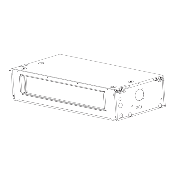
Page 20: Product Overview
PRODUCT OVERVIEW NOTE ON ILLUSTRATIONS: Illustrations in this manual are for explanatory purposes. The actual shape of your indoor unit may be slightly di erent. The actual shape shall prevail. The installation must be performed in accordance with the requirement of local and national standards. - Page 21 Install the Indoor Unit Select installation location NOTE Before installing the indoor unit, you must choose an appropriate location. The following are standards that will help you choose an appropriate location for the unit. Proper installation locations meet the following standards: Enough room exists for the There is no direct radiation Enough room exists for...
- Page 22 Confirm installation sizes Installation place The distance between the mounted indoor unit should meet the specifications illlustrated in the following diagram. >11.8in(30cm) Strong and durable ceiling Indoor unit >0.8in(2cm) Left side Right side >0.8in(2cm) >90.6in(230cm) >7.9in(20cm) >11.8in(30cm) Service access Ceiling Floor Floor Maintenance space...
- Page 23 Hang indoor unit 1. Please refer to the following diagrams to locate the four positioning screw bolt holes on the ceiling. Be sure to mark the paces where you will drill ceiling hook holes. Air outlet dimensions Air inlet dimensions (unit: mm/inch) SIZE OF AIR OUTLET...
- Page 24 Step1: Unpacking Step4: Hang indoor unit Carefully unpack the unit and inspect the contents Please turn the product face down and lift the mounting bracket onto the 4 pre-assembled for damage. If any damage is found at the time of screws, locking them with nuts.
- Page 25 Step9: Connect the drainpipe Step7: Install the control box cover Step10: Install air inlet channel panel Step8: Connect the refrigerant pipe Step11: Connect the duct Use tools to remove the knock-out holes Total 1500mm/59 inches minimum...
- Page 26 Airflow performance Airflow performance data is based on cooling performance with a coil and no filter in place. Select performance table for appropriate unit size external static applied to unit allows operation within the minimum and maximum limits shown in table below for both cooling and electric heat operation. External Static Pressure(in.w.c.) model Static pressure...
- Page 27 Step 8: Connect drain hose The drainpipe is used to drain water away from the unit. Improper installation may cause unit and property damage. CAUTION Insulate all piping to prevent condensation, • which could lead to water damage. U type tube If the drainpipe is bent or installed •...
- Page 28 2.9 Installation of electric auxiliary heat module (Only for HEAT function models) NOTICE Installation must be performed by an licensed contractor. Please make necessary precaution when performing the installation operation. Accessories Preparations for Installation Before installation, please confirm the electric Name Quantity Name...
- Page 29 Step 3 Step 6 Remove the electronic controller assembly. Installation of air circuit breaker (After mounting the air circuit breaker with screws, you need to connect the power cord to the input and output terminals respectively). Auxilliary heater electrical wire Step 4 Dismantle the guide plate.
- Page 30 Step 8 Install the control box cover. Step 9 Install the air inlet channel panel.
- Page 31 confirmation of indoor unit NOTICE Electric auxiliary heating wiring diagram packed with the accessories. If branch circuit wire length exceeds 100 ft, consult NEC 210-19a to determine maximum wire length. Use 2% voltage drop. After the electric heating wiring is connected, please confirm before power on: •...
- Page 32 Auxilliary Heater Electrical Data(Optional) EAH-03D(UL) 10.9/12.0 15.0/16.0 20.0/20.0 EAH-05D(UL) 18.1/19.7 22.0/24.0 25.0/30.0 EAH-08D(UL) 28.3/30.9 32.0/35.0 40.0/45.0 EAH-10D(UL) 35.5/38.7 40.0/43.0 45.0/50.0 Electric auxiliary heating wiring diagram T L1 BL U E HT R 1 T C0 1 B L UE TL 2 B L UE H T R2 T C0 2...
- Page 33 Connection Instructions—Refrigerant Piping CAUTION Insulate both the gas and liquid piping to prevent condensation. • Outdoor Unit Air Handler Air Handler Unit Adapter Required at Air Outdoor Adapter Required at Outdoor Connection Unit Model Connection(in.flare) Handler Unit(in.flare to braze) Model Unit(in.flare to flare or braze) (in.flare) Liquid...
- Page 34 • Clamp flare from on the end of the pipe. The end of the pipe must extend beyond the flare form. (Bigger Flare form Pipe Torque wrench • Place flaring tool onto the form. • Turn the handle of the flaring tool clockwise until the pipe is fully flared.
- Page 35 CAUTION • Thread this pipeline through the wall and connect it to the outdoor unit. Check to make sure there is no • Insulate all the piping, including the valves of refrigerant leak after completing the outdoor unit. Open the stop valves of the outdoor unit to •...
-
Page 36: Wiring Precautions
WIRING PRECAUTIONS WARNING BEFORE PERFORMING ANY ELECTRICAL WORK, READ THESE WARNINGS. All wiring must comply with local and national Do not let wires touch or rest against ● ● electrical codes, regulations and must be installed refrigerant tubing, the compressor, or any by a licensed electrician. - Page 37 INDOOR UNIT WIRING CAUTION • While connecting the wires, please strictly follow the wiring diagram. • The refrigerant circuit can become very hot. Keep the interconnection cable away from the copper tube. Step 1: Prepare the cable for connection. WARNING Using wire strippers, strip the insulating jacket from both ends of the signal cable to reveal ISOLATE THE POWER SUPPLY LEADS...
- Page 38 SPECIFIC WIRING METHODS WARNING Please refer to the wiring nameplate for the wiring method. Do not connect the power cord to the communication line, as this may damage the system. Connection method A: Connection method B: Refer to the wiring method of internal and To use a 24V thermostat, you need to refer to the external machine communication and wired following wiring:...
- Page 39 S4-2 Default on, DH function off. S4-1 Default on, W1 and W2 Turn switch off to activate DH shorted for single stage Aux heat function. operation. Turn off to separate stages. S4-2 Default on, DH function off. S4-1 Default on, W1 and W2 Turn switch off to activate DH shorted for single stage Aux heat function.
- Page 40 The fault warning: Optional function wiring: Alarm output: An alarm output (CN33) can be utilized if actions are required when a fault is present. This is a passive outlet port, so you will need to input a voltage signal. The relay is normally-open for normal operation, and closed when a fault condition is active.
- Page 41 Dehumidification control wiring Outdoor unit connector Connector Purpose Dehumidification control requires external Defrost control Humidistat at DH and R. Set S4-2 as OFF. When the humidity rises and exceeds the set value of the Humidistat, the 24V signal of DH changes LED display to 0V, the cooling system starts the dehumidification operation, and the air volume...
- Page 42 DIP switch definitions Function Rotary switch KEY1 Led display...
- Page 43 Function DIP switch settings: Function combination table of SW1-1 and SW1-4: The 24V thermostat mode needs to refer Control type Stand alone or full system to the following settings: Free match Free match Wired Full system controller Full system Thermostat 000 is the default 000/001/010/ 011/100/101/110/111,internal machines with di erent abilities,...
- Page 44 Available settings are 000/001/010/011. Each digit corresponds an indiviual swith position. 1,2,3 Electric heat nominal CFM adjustment For example [SW4-1 OFF, SW4-2 ON, SW4 -3 OFF] = 010 See table 11 for the corresponding CFM adjustment For dual stage supplemental heat, [Default] For single stage supplemental S4-1 Default ON...
- Page 45 Air volume table 24V thermostat Wired controller Air flow External Static volume Capacity Fan speed Electric heater kit Pressure Range DIP Switch 24V terminal engaged DIP Switch Mode (CFM) Cooling Turbo — SW3-4=ON Y2/Y — Cool Cooling High — SW3-4=OFF Y2/Y —...
- Page 46 Air volume table Air volume table 24V thermostat Wired controller Airflow External Static volume Capacity Fan Speed Electric heater kit Pressure Range DIP Switch 24V terminal engaged DIP Switch Mode (CFM) — SW3-4=ON Y2/Y — Cool Cooling Turbo 1188 — SW3-4=OFF Y2/Y —...
-
Page 47: Note On Adding Refrigerant
NOTE ON ADDING REFRIGERANT CAUTION DO NOT mix refrigerant types. Some systems require additional charging depending on pipe lengths. The standard pipe length varies according to local regulations. For example, in North America, the standard pipe length is 7.5m (25’). In other areas, the standard pipe length is 5m (16‘). -
Page 48: Test Run
TEST RUN CAUTION Failure to perform the test run may result in unit damage, property damage, or personal injury. 5. For the Outdoor Unit Before test run a. Check to see if the refrigeration system is leaking. A test run must be performed after the entire b. - Page 49 24V SIGNAL CHART 24V input terminal Mode Priority Y/Y2 E/AUX DH/DS/BK Fan speed Display Cooling stage 1 Cooling stage 2 High Dehumidification Dehumidification Heat pump stage 1 Heat pump stage 2 High Heat pump stage 2 High Emergency heat Turbo Emergency heat Turbo Emergency heat...
- Page 52 The design and specifications are subject to change without prior notice for product improvement. Consult with the sales agency or manufacturer for details. Any updates to the manual will be uploaded to the service website, please check for the latest version. QS001IU-PANCAKE 16123000003753 20230823...
- Page 53 此页及后面的页面无需印刷 技术要求: 1.80克/平方双胶纸 2.尺寸:A4 3.颜色:黑白 4.注意:排版时注意页码数字都是居中对齐 5.装订。...
Need help?
Do you have a question about the SLIM24 and is the answer not in the manual?
Questions and answers