innovair SLIM24 Installation And Owner's Manual
High efficiency wall mount system
Hide thumbs
Also See for SLIM24:
- Installation and owner's manual (128 pages) ,
- Installation and owner's manual (53 pages) ,
- Installation and owner's manual (56 pages)
Chapters
Table of Contents
Troubleshooting

Related Manuals for innovair SLIM24


Summary of Contents for innovair SLIM24
- Page 1 SLIM24 Hyper Heat Installation and Owner's Manual High Efficiency Wall Mount System Appearance of unit may vary. IMPORTANT NOTE: Read this manual carefully before installing or operating your new unit. Make sure to save this manual for future reference.
- Page 3 Indoor Unit - Air Handler T ype §. Outdoor Unit Dimensional Drawings Service Space Capacity Correction Factor for Height Di erence Noise Criterion Curves Refrigerant Cycle Diagrams Electrical Wiring Diagrams §. Installation §. Maintenance §. Product Features www.innovair.com ©2023 Innovair Corporation. All Rights Reserved.
- Page 4 Check Pr ocedures Appendix Temperature Sensor Resistance Value Table for T1,T2,T3 and T4 (°C – K) Temperature Sensor Resistance Value Table for TP(for some units) (°C – K) iii) Pressure On Service Port www.innovair.com ©2023 Innovair Corporation. All Rights Reserved.
- Page 5 ©2023 Innovair Corporation. All Rights Reserved.
- Page 6 Safety Precautions Contents Precautions ......................Information servicing(For ammable materials) ..........www.innovair.com ©2023 Innovair Corporation. All Rights Reserved.
- Page 7 When the unit is not to be used for an extended time, cal work. For more information, contact your dealer, disconnect the power supply or turn off the breaker. seller, or an authorized service center. Safety Precautions www.innovair.com ©2023 Innovair Corporation. All Rights Reserved.
- Page 8 This shall be reported to the owner of flammable refrigerant can possibly be released to the the equipment so all parties are advised. Initial safety surrounding space. checks shall include: Safety Precautions www.innovair.com ©2023 Innovair Corporation. All Rights Reserved.
- Page 9 • Check that cabling will not be subject to wear, • purge again with inert gas; corrosion, excessive pressure, vibration, sharp edges or any other adverse environmental effects. The check • open the circuit by cutting or brazing. Safety Precautions www.innovair.com ©2023 Innovair Corporation. All Rights Reserved.
- Page 10 (i.e. special cylinders for the recovery of • Become familiar with the equipment and its operation. refrigerant). Cylinders shall be complete with pressure relief valve and associated shut-off valves in good • Isolate system electrically. working order. Safety Precautions www.innovair.com ©2023 Innovair Corporation. All Rights Reserved.
- Page 11 When oil is drained from a any associated electrical components are sealed to system, it shall be carried out safely. prevent ignition in the event of a refrigerant release. Consult manufacturer if in doubt. Safety Precautions www.innovair.com ©2023 Innovair Corporation. All Rights Reserved.
- Page 12 Model Reference Contents Model Reference ....................2 External Appearance .....................3 www.innovair.com ©2023 Innovair Corporation. All Rights Reserved.
- Page 13 Refer to the following table to determine the specific indoor and outdoor unit model number of your purchased equipment. Indoor Unit Model Outdoor Unit Model Capacity (Btu/h) Power Supply WEV18H2R19 SHV18H2R20 WEV24H2R19 SHV24H2R20 1Ph, 208/230V~, 60Hz WEV30H2R19 SHV30H2R20 WEV36H2R19 SHV36H2R20 Model Reference 2 www.innovair.com ©2023 Innovair Corporation. All Rights Reserved.
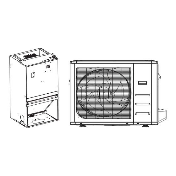
- Page 14 2. External Appearance Indoor Unit Air handler Outdoor Unit Single Fan Outdoor Unit Double Fan Outdoor Unit Model Reference 3 www.innovair.com ©2023 Innovair Corporation. All Rights Reserved.
-
Page 15: Table Of Contents
Indoor Unit-Air Handler Contents Feature........................2 Dimensional Drawings ..................3 Part names ......................4 Service Place ......................4 Accessories ......................5 Fan Performance ....................6 Noise Criterion Curves ...................8 Electrical Characteristics ..................10 Electrical Wiring Diagrams ..................11 www.innovair.com ©2023 Innovair Corporation. All Rights Reserved. -
Page 16: Feature
• Indoor unit is standard with Nitrogen injection to maintain positive pressure of the indoor unit. It is easy to check from the check valve whether there is leakage in the evaporator or not. IDU-Air Handler 2 www.innovair.com ©2023 Innovair Corporation. All Rights Reserved. -
Page 17: Dimensional Drawings
235.4 Return Air Opening Depth 10-9/32 13-2/32 332.5 Supply Air Opening Clearance 1-5/32 29.1 1-5/8 Return Air Opening Side 13/32 10.6 13/32 10.6 Clearance Return Air Opening Front 15/32 Clearance IDU-Air Handler 3 www.innovair.com ©2023 Innovair Corporation. All Rights Reserved. -
Page 18: Part Names
3. Part names Air outlet Air inlet 4. Service Place >0in ≥ 20in ≥ 24in ≥ 20in IDU-Air Handler 4 www.innovair.com ©2023 Innovair Corporation. All Rights Reserved. -
Page 19: Accessories
Transfer connector Installation of Electric Auxiliary Heat Module(for some models)(not supplied) Name Quantity Name Quantity Manual Silicone breaker cover Electric auxiliary heating Foam gasket wiring diagram Screw Circuit breaker label IDU-Air Handler 5 www.innovair.com ©2023 Innovair Corporation. All Rights Reserved. -
Page 20: Fan Performance
6. Fan Performance 0.1 0.148 0.2 External sta�c pressure (in.w.c.) 0.148 External sta�c pressure (in.w.c.) IDU-Air Handler 6 www.innovair.com ©2023 Innovair Corporation. All Rights Reserved. - Page 21 1200 1000 External sta�c pressure (in.w.c.) 1400 1200 1000 External sta�c pressure (in.w.c.) IDU-Air Handler 7 www.innovair.com ©2023 Innovair Corporation. All Rights Reserved.
-
Page 22: Noise Criterion Curves
-Sound level will vary depending on a range of factors such as the construction -(acoustic absorption coefficient) of particular room in which the equipment is installed. -The operating conditions are assumed to be standard. IDU-Air Handler 8 www.innovair.com ©2023 Innovair Corporation. All Rights Reserved. - Page 23 WEV18H2R19 WEV24H2R19 WEV30H2R19 WEV36H2R19 IDU-Air Handler 9 www.innovair.com ©2023 Innovair Corporation. All Rights Reserved.
-
Page 24: Electrical Characteristics
Line diameter(AWG) 12/4.0mm² 12/4.0mm² 12/4.0mm² 12/4.0mm² Power line Outdoor-indoor Line quantity Line diameter(AWG) 20/0.5mm 20/0.5mm 20/0.5mm 20/0.5mm Signal line Thermostat Line quantity Line diameter(AWG) 18/1.0mm 18/1.0mm 18/1.0mm 18/1.0mm Signal line IDU-Air Handler 10 www.innovair.com ©2023 Innovair Corporation. All Rights Reserved. -
Page 25: Electrical Wiring Diagrams
Indoor Fan Capacitor Indoor Fan Motor Indoor ECM Motor TO CCM Comm.Bus Central Controller Indoor Room Temperature Sensor Indoor Coil Inlet Temperature Sensor Indoor Coil Outlet Temperature Sensor Indoor Coil Temperature Sensor IDU-Air Handler 11 www.innovair.com ©2023 Innovair Corporation. All Rights Reserved. - Page 26 ©2023 Innovair Corporation. All Rights Reserved.
- Page 27 2. Although design voltage can support higher voltage ,but we strongly ask you connect the power less than 24V, current less than 0.5A 3. When the unit occurs the problem , the relay would be closed , then ALARM works www.innovair.com ©2023 Innovair Corporation. All Rights Reserved.
- Page 28 , but the remote controller/wire controller are on, CP code would be shown on the display board. 6. The voltage of the port is 12V DC, design Max. current is 5mA. www.innovair.com ©2023 Innovair Corporation. All Rights Reserved.
- Page 29 PCB as a spare part to use in another unit. Then you have to select the right position to match the size of the unit. “53” means 5.3kW (18K),“105” means 10.5kW(36K), and so on. www.innovair.com ©2023 Innovair Corporation. All Rights Reserved.
- Page 30 Ts),Wire controller demand with heat pump+Electric heat working together SW2-2 Electric heat on delay [Default] No Electric auxiliary heating delay Based on SW2-2 is SW2-3 30 minutes [Default] 15 minutes to start time www.innovair.com ©2023 Innovair Corporation. All Rights Reserved.
- Page 31 24V Thermostat is Turbo High applied for. Available settings are 000/001/010/011. Each digit Electric heat nominal CFM corresponds an individual switch position. 1,2,3 adjustment For example [SW4-1 OFF, SW4-2 ON, SW4 -3 OFF] = 010 www.innovair.com ©2023 Innovair Corporation. All Rights Reserved.
- Page 32 000/001/010/011/100/101/110/111, internal machines with di erent abilities, SW4-3 electric heating and PSC classification for use NOTICE: The SW4 DIP switch is only for Certified service technicians to debug and use, please do not touch it. www.innovair.com ©2023 Innovair Corporation. All Rights Reserved.
- Page 33 Function combination table of SW1-1 and SW1-4 Control type Stand alone or full system Free match Free match Wired controller Full system 24V Thermostat Full system 24V Thermostat Stand alone www.innovair.com ©2023 Innovair Corporation. All Rights Reserved.
- Page 34 Outdoor Unit Contents Dimensional Drawings ..................2 Service Place ......................18 Capacity Correction Factor for Height Difference ..........19 Noise Criterion Curves ..................25 Refrigerant Cycle Diagrams ................27 Electrical Wiring Diagrams ..................30 www.innovair.com ©2023 Innovair Corporation. All Rights Reserved.
-
Page 35: Dimensional Drawings
1. Dimensional Drawings Please check the corresponding dimensional drawing according to the panel plate. Outdoor Unit Model Panel Plate SHV18H2R20 X430 SHV24H2R20 SHV30H2R20 SHV36H2R20 Outdoor Unit 2 www.innovair.com ©2023 Innovair Corporation. All Rights Reserved. - Page 36 Panel Plate X230 (Rounded grille 1) Outdoor Unit 3 www.innovair.com ©2023 Innovair Corporation. All Rights Reserved.
- Page 37 Panel Plate X230 (Rounded grille 2) Outdoor Unit 4 www.innovair.com ©2023 Innovair Corporation. All Rights Reserved.
- Page 38 Panel Plate X230(Square grille) Outdoor Unit 5 www.innovair.com ©2023 Innovair Corporation. All Rights Reserved.
- Page 39 X330(Rounded grille 1) Panel Plate Outdoor Unit 6 www.innovair.com ©2023 Innovair Corporation. All Rights Reserved.
- Page 40 X330(Rounded grille 2) Panel Plate Outdoor Unit 7 www.innovair.com ©2023 Innovair Corporation. All Rights Reserved.
- Page 41 X330(Square grille) Panel Plate Outdoor Unit 8 www.innovair.com ©2023 Innovair Corporation. All Rights Reserved.
- Page 42 X430(Rounded grille 1) Panel Plate Outdoor Unit 9 www.innovair.com ©2023 Innovair Corporation. All Rights Reserved.
- Page 43 X430(Rounded grille 2) Panel Plate Outdoor Unit 10 www.innovair.com ©2023 Innovair Corporation. All Rights Reserved.
- Page 44 X430(Square grille) Panel Plate Outdoor Unit 11 www.innovair.com ©2023 Innovair Corporation. All Rights Reserved.
- Page 45 Panel Plate D30(Rounded grille 1) Outdoor Unit 12 www.innovair.com ©2023 Innovair Corporation. All Rights Reserved.
- Page 46 Panel Plate D30(Rounded grille 2) Outdoor Unit 13 www.innovair.com ©2023 Innovair Corporation. All Rights Reserved.
- Page 47 Panel Plate D30(Square grille) Outdoor Unit 14 www.innovair.com ©2023 Innovair Corporation. All Rights Reserved.
- Page 48 Panel Plate E30(Square grille) Outdoor Unit 15 www.innovair.com ©2023 Innovair Corporation. All Rights Reserved.
- Page 49 Panel Plate E30(Rounded grille 1) Outdoor Unit 16 www.innovair.com ©2023 Innovair Corporation. All Rights Reserved.
- Page 50 Panel Plate E30(Rounded grille 2) Outdoor Unit 17 www.innovair.com ©2023 Innovair Corporation. All Rights Reserved.
-
Page 51: Service Place
2. Service Place Outdoor Unit 18 www.innovair.com ©2023 Innovair Corporation. All Rights Reserved. -
Page 52: Capacity Correction Factor For Height Difference
5/16.4 0.995 0.983 0.960 0.937 Height di erence 1.000 0.988 0.965 0.942 H (m) -5/-16.4 1.000 0.988 0.965 0.942 Outdoor Upper -10/-32.8 0.988 0.965 0.942 than Indoor -20/-65.6 0.965 0.942 Outdoor Unit 19 www.innovair.com ©2023 Innovair Corporation. All Rights Reserved. - Page 53 -5/-16.4 0.992 0.989 0.983 0.977 0.970 0.964 H (m) -10/- 0.981 0.975 0.969 0.963 0.957 32.8 Outdoor Upper than Indoor -20/- 0.967 0.961 0.955 0.949 65.6 -25/-82 0.953 0.947 0.941 Outdoor Unit 20 www.innovair.com ©2023 Innovair Corporation. All Rights Reserved.
- Page 54 0.945 0.929 H (m) -5/-16.4 0.992 0.984 0.969 0.953 0.937 0.922 -10/-32.8 0.976 0.961 0.945 0.930 0.914 Outdoor Upper than Indoor -20/-65.6 0.953 0.938 0.922 0.907 -25/-82 0.930 0.915 0.900 Outdoor Unit 21 www.innovair.com ©2023 Innovair Corporation. All Rights Reserved.
- Page 55 0.945 0.927 H (m) -5/-16.4 0.992 0.980 0.968 0.956 0.938 0.920 -10/-32.8 0.972 0.960 0.948 0.930 0.912 Outdoor Upper than Indoor -20/-65.6 0.952 0.941 0.923 0.905 -30/-98.4 0.933 0.915 0.898 Outdoor Unit 22 www.innovair.com ©2023 Innovair Corporation. All Rights Reserved.
- Page 56 0.936 0.915 H (m) -5/-16.4 0.992 0.978 0.964 0.950 0.929 0.908 -10/-32.8 0.970 0.956 0.942 0.921 0.900 Outdoor Upper than Indoor -20/-65.6 0.949 0.935 0.914 0.893 -30/-98.4 0.927 0.907 0.886 Outdoor Unit 23 www.innovair.com ©2023 Innovair Corporation. All Rights Reserved.
- Page 57 0.932 0.909 H (m) -5/-16.4 0.992 0.977 0.962 0.947 0.924 0.902 -10/-32.8 0.969 0.954 0.939 0.917 0.895 Outdoor Upper than Indoor -20/-65.6 0.947 0.932 0.910 0.887 -30/-98.4 0.924 0.902 0.880 Outdoor Unit 24 www.innovair.com ©2023 Innovair Corporation. All Rights Reserved.
-
Page 58: Noise Criterion Curves
-Sound level will vary depending on arrange o actors such as the construction (acoustic absorption coefficient) of particular room in which the equipment is installed. -The operating conditions are assumed to be standard. Outdoor Unit 25 www.innovair.com ©2023 Innovair Corporation. All Rights Reserved. - Page 59 MOX430U-18HFN1-M MOD30-24HFN1-MW MOD30U-30HFN1-MR0(X) MOE31U-36HFN1-M Outdoor Unit 26 www.innovair.com ©2023 Innovair Corporation. All Rights Reserved.
-
Page 60: Refrigerant Cycle Diagrams
Pipe Size (Diameter:ø) Piping length (m/ft) Elevation (m/ft) mm(inch) Model No. Additional Refrigerant Liquid Rated Max. Rated Max. MOX430U-18HFN1-M 19(3/4) 9.52(3/8) 7.5/24.6 30/98.4 20/65.6 65g/m (0.69oz/ft) MOD30U-30HFN1-MR0(X) 19(3/4) 9.52(3/8) 7.5/24.6 50/164 25/82 Outdoor Unit 27 www.innovair.com ©2023 Innovair Corporation. All Rights Reserved. - Page 61 Pipe Size (Diameter:ø) Piping length (m/ft) Elevation (m/ft) mm(inch) Model No. Additional Refrigerant Liquid Rated Max. Rated Max. MOD30-24HFN1-MW 19(3/4) 9.52(3/8) 7.5/24.6 50/164 25/82 65g/m (0.69oz/ft) Outdoor Unit 28 www.innovair.com ©2023 Innovair Corporation. All Rights Reserved.
- Page 62 Pipe Size (Diameter:ø) Piping length (m/ft) Elevation (m/ft) mm(inch) Model No. Additional Refrigerant Liquid Rated Max. Rated Max. MOE31U-36HFN1-M 19(3/4) 9.52(3/8) 7.5/24.6 65/213 30/98.4 65g/m (0.69oz/ft) Outdoor Unit 29 www.innovair.com ©2023 Innovair Corporation. All Rights Reserved.
-
Page 63: Electrical Wiring Diagrams
MOD30-24HFN1-MW 16022000036170 MOD30U-30HFN1-MR0(X) MOE31U-36HFN1-M 16022000036969 ODU Main Printed Circuit Inverter Module ODU Model 24V Printed Board Board Printed Board SHV18H2R20 17122000048064 17122000054047 MOD30-24HFN1-MW 17122000047742 17122000054047 MOD30U-30HFN1-MR0(X) MOE31U-36HFN1-M 17122000037804 17122000042012 17122000054047 Outdoor Unit 30 www.innovair.com ©2023 Innovair Corporation. All Rights Reserved. - Page 64 ©2023 Innovair Corporation. All Rights Reserved.
- Page 65 ©2023 Innovair Corporation. All Rights Reserved.
- Page 66 ©2023 Innovair Corporation. All Rights Reserved.
- Page 67 Outdoor unit printed circuit board diagram: 17122000048064& 17122000048066 RC 2 VU B www.innovair.com ©2023 Innovair Corporation. All Rights Reserved.
- Page 68 IPM1 IPM for compressor CN27 connect to compressor CN28 0V AC (standby) CN29 200-300V AC (running) EE_PORT CN505 EEPROM programer port Note: This section is for reference only. Please take practicality as standard. www.innovair.com ©2023 Innovair Corporation. All Rights Reserved.
- Page 69 Outdoor unit printed circuit board diagram: 17122000047742 www.innovair.com ©2023 Innovair Corporation. All Rights Reserved.
- Page 70 COMPRESSOR 0V AC (standby) 10-200V AC (running) DC-FAN CN32 connect to DC fan CN31 S: connect to indoor unit communication(pin1-pin2: 24VDC Pulse wave; S-C(mono) CN34 pin2-pin3: 208-230V AC input) www.innovair.com ©2023 Innovair Corporation. All Rights Reserved.
- Page 71 CN21 HEAT_Y CN36 4-WAY CN38 connect to 4 way valve, 208-230V AC when is ON. CN27 connect to key board CN1 Note: This section is for reference only. Please take practicality as standard. www.innovair.com ©2023 Innovair Corporation. All Rights Reserved.
- Page 72 Outdoor unit printed circuit board diagram: 17122000037804 www.innovair.com ©2023 Innovair Corporation. All Rights Reserved.
- Page 73 T2B T4 T3 connect to pipe temp. sensor T3, ambient temp. sensor T4 CN15/CN23/CN26/ connect to Electric Expansion Valve(A~F) CN30/CN33/CN38 connect to IPM&PFC board CN9 CN22 Communication to indoor unit www.innovair.com ©2023 Innovair Corporation. All Rights Reserved.
- Page 74 Outdoor unit IPM board diagram: 17122000042012 www.innovair.com ©2023 Innovair Corporation. All Rights Reserved.
- Page 75 N-Out connect to main board CN6 FAN_DC FAN_1/FAN_2 connect to outdoor DC fan 1& DC fan 2 CN_COMP connect to compressor Note: This section is for reference only. Please take practicality as standard. www.innovair.com ©2023 Innovair Corporation. All Rights Reserved.
- Page 76 Outdoor unit printed circuit board diagram: 17122000054047 www.innovair.com ©2023 Innovair Corporation. All Rights Reserved.
- Page 77 (5VDC) H-PRO CN38 connect to high pressure switch (5VDC) connect to main board L-Out Power Supply connect to main board N-Out Note: This section is for reference only. Please take practicality as standard. www.innovair.com ©2023 Innovair Corporation. All Rights Reserved.
- Page 78 Location Selection Indoor Unit Installation Outdoor Unit Installation Drainage Pipe Installation Duct work Refrigerant Pipe Installation Vacuum Drying and Leakage Checking Additional Refrigerant Charge Engineering of Insulation Engineering of Electrical Wiring Test Operation www.innovair.com ©2023 Innovair Corporation. All Rights Reserved.
-
Page 79: Installation Overview
Install the outdoor unit Install the drainpipe Evacuate the r efrigeration system Connect the wires Connect the refrigerant pipes Install the panel Perform a test run (only for cassette type) 1. Installation Overview www.innovair.com ©2023 Innovair Corporation. All Rights Reserved. -
Page 80: Location Selection
1/2H < L ≤ H more 2.7 If the unit is frequently exposed to salty L > H Can not be installed air (seaside): Use outdoor unit that is specially designed to resist corrosion. 2. Location selection www.innovair.com ©2023 Innovair Corporation. All Rights Reserved. -
Page 81: Indoor Unit Installation
SUPPORTING 2"X4" STRUCTURE WOOD SCREWS NOTE: MOUNTING WALL AND SUPPORTING WALLMOUNT BRACKET STRUCTURE MUST BE ABLE TO SUPPORT A MINIMUM OF 165 LBS. WOOD SCREWS WALL MOUNT Front return air 3. IDU Installation-AHU www.innovair.com ©2023 Innovair Corporation. All Rights Reserved. - Page 82 2. The part you need to punch the mounting holes has a total of 12 screws. 5. Remove the mounting template sheet, put the mounting bracket on the mounting hole, and fix the upper and lower brackets with 6 screws respectively. 3. IDU Installation-AHU www.innovair.com ©2023 Innovair Corporation. All Rights Reserved.
- Page 83 EXITS ON EITHER SECONDARY SIDE OF UNIT DRAIN 2" / 51mm (TRAP EXTERNAL PRIMARY TO UNIT) DRAIN 2" / 51mm MIN DRAIN Note: Use metal drains in the area above the cover. 3. IDU Installation-AHU www.innovair.com ©2023 Innovair Corporation. All Rights Reserved.
- Page 84 Electric auxiliary 3. Remove the terminal block and power wires, loosen the Foam gasket heating wiring screws, and remove the electric auxiliary heating cover. diagram Circuit breaker Screw label 3. IDU Installation-AHU www.innovair.com ©2023 Innovair Corporation. All Rights Reserved.
- Page 85 NOTICE: Electric auxiliary heating wiring diagram packed with the accessories. If branch circuit wire length exceeds 100 ft, consult the 3. IDU Installation-AHU www.innovair.com ©2023 Innovair Corporation. All Rights Reserved.
- Page 86 Auxiliary Heater Electrical Data(Optional) CIRCUIT 1 Internal Heater Heater Circuit Heater part No. Protection MCA (1) MOCP (2) Amps EAH- Ckt Bkr 10.8/12.0 14.0/16.0 15.0/20.0 03C(UL) EAH- Ckt Bkr 18.0/20.0 23.0/27.0 25.0/30.0 05C(UL) 3. IDU Installation-AHU www.innovair.com ©2023 Innovair Corporation. All Rights Reserved.
-
Page 87: Outdoor Unit Installation
If the drain joint doesn’t come with a rubber seal (see Fig. B ), do the following: 1. Insert the drain joint into the hole in the base pan of the unit. The drain joint will click in place. 4. Outdoor unit installation www.innovair.com ©2023 Innovair Corporation. All Rights Reserved. - Page 88 Make concrete foundation according to the specifications of the outdoor units. Fasten the feet of this unit with bolts firmly to prevent it from collapsing in case of earthquake or strong wind. 4. Outdoor unit installation www.innovair.com ©2023 Innovair Corporation. All Rights Reserved.
-
Page 89: Drainage Pipe Installation
(mm) 1/50 1/100 PVC25 For branch pipe PVC32 Could be PVC40 used for PVC50 confluence PVC63 pipe Attention: Adopt PVC40 or bigger pipe to be the main pipe. 5. Drainage Pipe Installation www.innovair.com ©2023 Innovair Corporation. All Rights Reserved. -
Page 90: Duct Work
9. The end of drainage pipe shall not contact with ground Fibrous ductwork may be used if constructed and installed directly. in accordance with SMACNA Construction Standard on Fibrous Glass Ducts. Ductwork must comply with National 5. Drainage Pipe Installation www.innovair.com ©2023 Innovair Corporation. All Rights Reserved. - Page 91 External Static Pressure(in.w.c.) Model Turbo Watts 82.6 108.3 121.3 152.1 196.3 High Watts 70.7 99.6 104.5 132.3 181.3 Medium Watts 59.4 78.8 92.5 121.3 166.2 Watts 50.6 75.3 104.5 110.4 152.3 5. Drainage Pipe Installation www.innovair.com ©2023 Innovair Corporation. All Rights Reserved.
-
Page 92: Refrigerant Pipe Installation
10. Set the wall conduit 10m/32.8ft (≥36000Btu/h unit) 7.2 The procedure of connecting pipes 1.Choose the pipe size according to the specification table. 2.Confirm the cross way of the pipes. 7. Refrigerant Pipe Installation www.innovair.com ©2023 Innovair Corporation. All Rights Reserved. - Page 93 3/4" (19) (49.4~74.5) 85-110 7/8" (22) (62.7-81.1) 7.3. Air-Handler Air Conditioners Refrigerant Piping Connection Correct Refrigerant piping Connecting installation methods Plan 1 7. Refrigerant Pipe Installation www.innovair.com ©2023 Innovair Corporation. All Rights Reserved.
-
Page 94: Vacuum Drying And Leakage Checking
1. Finding moisture during flushing refrigerant pipe. 2. Conducting construction on rainy day, because rain water might penetrated into pipeline. 3. Construction period is long, and rain water might penetrated into pipeline. 8. Vacuum Drying and Leakage Checking www.innovair.com ©2023 Innovair Corporation. All Rights Reserved. -
Page 95: Additional Refrigerant Charge
The linking part should be use glue to paste to- gether Be sure not bind the insulation material over-tight, it may extrude out the air in the material to cause bad 9. Additional Refrigerant Charge www.innovair.com ©2023 Innovair Corporation. All Rights Reserved. -
Page 96: Engineering Of Electrical Wiring
For the other regions: Rated Current of Nominal Cross-Sectional Appliance (A) Area(mm ≤ 6 0.75 6 - 10 10 - 16 16 - 25 25 - 32 32 - 45 11. Engineering of Electrical Wring www.innovair.com ©2023 Innovair Corporation. All Rights Reserved. - Page 97 S4-2 Default on , DH function o . S4-1 Default on, W1 and W2 Turn switch o to activate DH shorted for single stage Aux heat function. operation. Turn o to separate stages. 11. Engineering of Electrical Wring www.innovair.com ©2023 Innovair Corporation. All Rights Reserved.
- Page 98 Dehumidification control requires indirect humidifier at DH and R. Set S4-2 as OFF. When the humidity rises and exceeds the set value of the humidifier, the 24V 11. Engineering of Electrical Wring www.innovair.com ©2023 Innovair Corporation. All Rights Reserved.
-
Page 99: Test Operation
4. Drainage Test a. Ensure the drainpipe flows smoothly. New buildings should perform this test before finishing the ceiling. 11. Engineering of Electrical Wring www.innovair.com ©2023 Innovair Corporation. All Rights Reserved. - Page 100 Make sure that there are no leaks in any of the piping. g. Stop the air conditioner. Turn o the main power switch and reinstall the test cover. 12. Test Operation www.innovair.com ©2023 Innovair Corporation. All Rights Reserved.
- Page 101 Maintenance Contents First Time Installation Check ................. Refrigerant Recharge .................... Re-Installation ....................... Indoor Unit ....................5 Outdoor Unit ....................7 www.innovair.com ©2023 Innovair Corporation. All Rights Reserved.
-
Page 102: First Time Installation Check
If there is gas leakage, bubbles will form • Corroding the refrigerant system. on the connection. Air purging with vacuum pump Maintenance 2 www.innovair.com ©2023 Innovair Corporation. All Rights Reserved. - Page 103 Fully open the 2- and 3-way valves and tighten the evacuating for an additional 20 minutes. cap of the 2- and 3-way valves. • If the pressure does not achieve -0.1 MPa (14.5 Psi) after 50 minutes, check for leakage. Maintenance 3 www.innovair.com ©2023 Innovair Corporation. All Rights Reserved.
-
Page 104: Refrigerant Recharge
11. Use a torque wrench to tighten the caps to a torque Place the charging cylinder onto an electronic scale of 18 N.m. and record the starting weight. 12. Check for gas leakage. Fully open the Handle Lo manifold valve, 2- and Maintenance 4 www.innovair.com ©2023 Innovair Corporation. All Rights Reserved. -
Page 105: Re-Installation
Use a torque wrench to tighten the caps to a torque quickly. of 18 N.m. Close the 2-way valve. Check for gas leakage. Operate the air conditioner in cooling mode. Cease operations when the gauge reaches 0.1 MPa (14.5 Psi). Maintenance 5 www.innovair.com ©2023 Innovair Corporation. All Rights Reserved. - Page 106 Fully open the 2- and 3-way valves and tighten the an additional 20 minutes. cap of the 2- and 3-way valves. • If the pressure does not achieve -0.1 MPa (14.5 Psi) after 50 minutes, check for leakage. Maintenance 6 www.innovair.com ©2023 Innovair Corporation. All Rights Reserved.
-
Page 107: Outdoor Unit
-0.1 MPa (14.5Psi). valves. Close the valve (Low side) on the charge set and turn Use a torque wrench to tighten the caps to a torque off the vacuum pump. of 18 N.m. Maintenance 7 www.innovair.com ©2023 Innovair Corporation. All Rights Reserved. - Page 108 Note: 1. Mechanical connectors used indoors shall comply with local regulations. 2. When mechanical connectors are reused indoors, sealing parts shall be renewed. When flared joints are reused indoors, the flare part shall be re-fabricated. Maintenance 8 www.innovair.com ©2023 Innovair Corporation. All Rights Reserved.
- Page 109 Auto Mode ....................Drying Mode ....................Forced Operation Function ................Timer Function ....................Sleep Function ....................3.10 Auto-Restart Function ..................Remote Controller Functions ................7 LCD W ired Remote Controller ............... Centralized Contr oller ................. www.innovair.com ©2023 Innovair Corporation. All Rights Reserved.
-
Page 110: Display Function
Heating zone control Heating zone control NOTICE: 1 : signal 0 : no signal * :1 or 0 If the input does not meet the above, press shutdown for processing. Product Features 2 www.innovair.com ©2023 Innovair Corporation. All Rights Reserved. -
Page 111: Safety Features
Adjusted setting temperature • When T1-Tsc is lower than or equal to 0.5°C, fan In this manual, such as CDIFTEMP, HDIFTEMP2,TEH2, TCE1, TCE2...etc., they are well-setting parameter of EEPROM. Product Features 3 www.innovair.com ©2023 Innovair Corporation. All Rights Reserved. -
Page 112: Heating Mode(Heat Pump Units)
• O : Compressor stops. • Decrease: Decrease the running frequency to the lower TE1=0 level per 1 minute. 2) Auto fan action in heating mode: • Hold: Keep the current frequency. Product Features 4 www.innovair.com ©2023 Innovair Corporation. All Rights Reserved. -
Page 113: Auto Mode
• If the machine switches mode between heating and compressor running time is more than EE_TIME_ cooling, the compressor will keep stopping for certain DEFROST7+30. time and then choose mode according to Product Features 5 www.innovair.com ©2023 Innovair Corporation. All Rights Reserved. -
Page 114: Drying Mode
If the unit is o now, it does not start up immediately after the “timer o ” function is set. When the setting time is reached, the timer LED switches o and the unit running mode remains unchanged. Product Features 6 www.innovair.com ©2023 Innovair Corporation. All Rights Reserved. -
Page 115: Remote Controller Functions
To set 1 to 2 hours delay o for each day or a whole day o To set temperature, time and timer in a weekly timer schedule. 6. TIMER button 12. CHILD LOCK button To set timer on and timer o time of one day Product Features 7 www.innovair.com ©2023 Innovair Corporation. All Rights Reserved. - Page 116 HORIZONTAL SWING Displays selected fan display Active clean display speed: VERTICAL SWING Intelligent eye display display Secondary unit Electric heating display HIGH display Main unit and secondary AUTO unit display Product Features 8 www.innovair.com ©2023 Innovair Corporation. All Rights Reserved.
- Page 117 For some models: the wired controller connects to the unit HA and HB ports through the HA and HB ports. There is no polarity between HA and HB. Indoor Unit HA HB Wired Controller Product Features 9 www.innovair.com ©2023 Innovair Corporation. All Rights Reserved.
- Page 118 HA HB ..Wired Controller 1 Putty Trap Putty Putty Trap Trap Note: DO NOT allow water to enter the remote control. Use the trap and putty to seal the wires. Product Features 10 www.innovair.com ©2023 Innovair Corporation. All Rights Reserved.
-
Page 119: Centralized Controller
If there is any CAC (central air conditioner ) connecting with the central controller at the same time, please set the address from largest (63,62,61…), since the CAC units could obtain address automatically from the smallest (00,01,02…) Product Features 11 www.innovair.com ©2023 Innovair Corporation. All Rights Reserved. - Page 120 7.10 PC 03/PC 31 (Low Pressure Protection Diagnosis and Solution) ....31 7.11 PC 02 (Top temperature protection of compressor or High temperature protection of IPM module Diagnosis and Solution) ........32 7.12 EC 0d (Outdoor unit malfunction Diagnosis and Solution) ......33 www.innovair.com ©2023 Innovair Corporation. All Rights Reserved.
- Page 121 7.26 FL 09(Indoor and outdoor mismatch malfunction diagnosis and solution) ..47 7.27 PC 41(Outdoor compressor current sampling circuit failure diagnosis and solution) ......................48 7.28 EH b3 (Communication error between wired controller and indoor unit Diagnosis and Solution) ................48 Check Pr ocedures ....................www.innovair.com ©2023 Innovair Corporation. All Rights Reserved.
-
Page 122: Safety Caution
For models that cannot be measured, wait 5 minutes after the power supply is off to ensure that the capacitors are fully discharged. Note: This picture is for reference only. Actual appearance may vary. Troubleshooting 3 www.innovair.com ©2023 Innovair Corporation. All Rights Reserved. -
Page 123: General Troubleshooting
Over voltage or over low voltage protection TS29 PC 01 Top temperature protection of compressor or High temperature protection of IPM module TS32 PC 02 Inverter compressor drive error TS30 PC 04 Troubleshooting 4 www.innovair.com ©2023 Innovair Corporation. All Rights Reserved. - Page 124 Malfunction or Protection Solution Communication error between wire controller and indoor unit TS48 EH 3 The other error codes displayed on the wire controller are same from those on the unit. Troubleshooting 5 www.innovair.com ©2023 Innovair Corporation. All Rights Reserved.
- Page 125 High temperature protection of IPM module TS32 lc 06 Outdoor IPM module temperature sensor fault TS41 EC 55 High temperature protection of evaporator PH 90 Low temperature protection of evaporator PH 91 Troubleshooting 6 www.innovair.com ©2023 Innovair Corporation. All Rights Reserved.
-
Page 126: Outdoor Unit Point Check Function
If the value is higher than 99, the digital display tube will show EXV open angle single digit and tens digit. For example, the digital display tube show “2.0”,it means the EXV open angle is 120×4=480p.) Troubleshooting 7 www.innovair.com ©2023 Innovair Corporation. All Rights Reserved. - Page 127 For example, the digital display tube shows “Cd”, it means AD and low pressure sensor value is 205. When there is no pressure sensor, it is displayed as -- The currently running communication protocol 00-99 version Troubleshooting 8 www.innovair.com ©2023 Innovair Corporation. All Rights Reserved.
-
Page 128: Information Inquiry
"On/Off" for 2s to exit. When the remote control does not burn any parameters, the max. set temperature will not be memorized.(Set within 1 minute after power on) Troubleshooting 9 www.innovair.com ©2023 Innovair Corporation. All Rights Reserved. - Page 129 Settings, the code displayed is “Ch”, then press "OK" to send the Query Cooling Temperature Compensation Value code; press the Up/Down key to select the cooling temperature compensation value, then press "OK"; and press "On/Off" for 2s to exit. Troubleshooting 10 www.innovair.com ©2023 Innovair Corporation. All Rights Reserved.
- Page 130 Exit of engineer mode: 1)In engineer mode, press the key combination of “On/Off + Air speed” for 2s; 2)The engineer mode will be exited if there are no valid key operations for continuous 60s. Troubleshooting 11 www.innovair.com ©2023 Innovair Corporation. All Rights Reserved.
- Page 131 PC 03 Outdoor low ambient temperature protection pc 0l Evaporator coil temperature over high protection PH 90 Evaporator coil temperature over low Protection PH 91 Condenser high temperature protection PC 0A Troubleshooting 12 www.innovair.com ©2023 Innovair Corporation. All Rights Reserved.
-
Page 132: Error Diagnosis And Troubleshooting Without Error Code
The unit starts up and stops frequently TS15 - TS16 Unit runs continuously but insufficient cooling(heating) TS15 - TS16 Cool can not change to heat TS15 - TS16 Unit is noisy TS15 - TS16 Troubleshooting 13 www.innovair.com ©2023 Innovair Corporation. All Rights Reserved. -
Page 133: Field Maintenance
High suction pressure TS17 - TS18 Low suction pressure TS17 - TS18 Unit runs continuously but insufficient cooling TS17 - TS18 Too cool TS17 - TS18 Compressor is noisy TS17 - TS18 Troubleshooting 14 www.innovair.com ©2023 Innovair Corporation. All Rights Reserved. - Page 134 Troubleshooting 15 www.innovair.com ©2023 Innovair Corporation. All Rights Reserved.
- Page 135 Unit runs, but shortly stops The unit starts up and stops frequently Unit runs con�nuously but insufficient cooling(hea�ng) Cool can not change to heat Unit is noisy Test method / remedy Troubleshooting 16 www.innovair.com ©2023 Innovair Corporation. All Rights Reserved.
- Page 136 High discharge pressure Low discharge pressure High suc�on pressure Low suc�on pressure Unit runs con�nuously but insufficient cooling Too cool Compressor is noisy Horizontal louver can not revolve Test method / remedy Troubleshooting 17 www.innovair.com ©2023 Innovair Corporation. All Rights Reserved.
- Page 137 High discharge pressure Low discharge pressure High suc�on pressure Low suc�on pressure Unit runs con�nuously but insufficient cooling Too cool Compressor is noisy Horizontal louver can not revolve Test method / remedy Troubleshooting 18 www.innovair.com ©2023 Innovair Corporation. All Rights Reserved.
-
Page 138: Quick Maintenance By Error Code
PC 02 PC 04 PC 03 replacement /72/73 Indoor PCB Outdoor PCB Outdoor fan motor T3 Sensor TP Sensor Pressure sensor Reactor Compressor IPM module board Low pressure protector Additional refrigerant Troubleshooting 19 www.innovair.com ©2023 Innovair Corporation. All Rights Reserved. - Page 139 Outdoor fan motor T3 Sensor TP Sensor Pressure sensor Reactor Compressor IPM module board Data adapter board High pressure valve assy High pressure protector Low pressure protector Additional refrigerant Electric control box Troubleshooting 20 www.innovair.com ©2023 Innovair Corporation. All Rights Reserved.
-
Page 140: Troubleshooting By Error Code
This pictures are only for reference, actual appearance may vary. Troubleshooting and repair of compressor driven chip EEPROM parameter error and communication error between outdoor main chip and compressor driven chip are same as EC 51. Troubleshooting 21 www.innovair.com ©2023 Innovair Corporation. All Rights Reserved. -
Page 141: El 01 (Indoor And Outdoor Unit Communication Error Diagnosis And Solution)
Replace the signal wire . broken? Check whether the signal wires Pull out and insert back . insert on PCB well ? Replace indoor main PCB, is the error distinguished? Replace the outdoor main PCB. Troubleshooting 22 www.innovair.com ©2023 Innovair Corporation. All Rights Reserved. -
Page 142: Eh 03 / Ec 07 (Fan Speed Is Operating Outside Of The Normal Range )/Ec
Check the wiring of fan motor. Is it improperly wired? Ensure proper connections Measure the voltage for the fan motor from the PCB. Is it within normal parameters? Replace the main PCB Replace the fan motor Troubleshooting 23 www.innovair.com ©2023 Innovair Corporation. All Rights Reserved. - Page 143 Release the UVW connector. Measure the resistance of U-V, U-W, V-W. If the resistance is not equal to each other, the fan motor must has problems and need to be replaced. otherwise the PCB must has problems and need to be replaced. Troubleshooting 24 www.innovair.com ©2023 Innovair Corporation. All Rights Reserved.
-
Page 144: Eh 60/Eh 61/Ec 53/Ec 52/Ec 54/Ec 56/Ec 57/Ec 50/Ec 5C
Is it within acceptable Replace the sensor. parameters? Replace indoor PCB((EH XX ) or outdoor PCB(EC XX ) This picture and the value are only for reference, actual appearance and value may vary Troubleshooting 25 www.innovair.com ©2023 Innovair Corporation. All Rights Reserved. -
Page 145: El 0C (Refrigerant Leakage Detection Diagnosis And Solution)
Check system for leakages . Replace the indoor PCB Repair the leakage and Are any leakages present ? recharge the refrigerant . Charge the refrigerant appropriately(about 10 % of the nameplate charge) Troubleshooting 26 www.innovair.com ©2023 Innovair Corporation. All Rights Reserved. -
Page 146: Eh 0E(Water-Level Alarm Malfunction Diagnosis And Solution)
Insert the water -level switch Is the water -level switch properly inserted properly? If the water -level switch is Replace the water -level switch broken? Replace the indoor main PCB Troubleshooting 27 www.innovair.com ©2023 Innovair Corporation. All Rights Reserved. -
Page 147: Pc 00(Ipm Malfunction Or Igbt Over-Strong Current Protection Diagnosis And Solution)
Check the compressor Check the compressor resistance values. resistance values. Are they uniform? Replace the compressor. Are they uniform? Replace the compressor. Replace the outdoor PCB. Replace the outdoor PCB. Troubleshooting 28 www.innovair.com ©2023 Innovair Corporation. All Rights Reserved. -
Page 148: Pc 01(Over Voltage Or Too Low Voltage Protection)/Pc
Replace the IPM board. DC 310V, 340V or 380V? When start up the unit, is it in 220V~400V? Check the reactor. Is it in working order? Replace outdoor PCB. Replace the reactor. Troubleshooting 29 www.innovair.com ©2023 Innovair Corporation. All Rights Reserved. -
Page 149: Pc 04(Inverter Compressor Drive Error Diagnosis And Solution)
Is it functioning Please refer to “Fan properly? Speed Malfunction” Check the compressor resistance values. Are they within Replace the compressor. acceptable parameters? Replace the outdoor PCB. Troubleshooting 30 www.innovair.com ©2023 Innovair Corporation. All Rights Reserved. -
Page 150: Pc 03/Pc 31(Low Pressure Protection Diagnosis And Solution)
Check whether the refrigerant function properly after more system is functioning properly. function properly after more system is functioning properly. refrigerant is added? refrigerant is added? Troubleshooting 31 www.innovair.com ©2023 Innovair Corporation. All Rights Reserved. -
Page 151: Protection Of Ipm Module Diagnosis And Solution)
Replace the OLP. system the OLP. Is it zero? is normal? Replace the outdoor control PCB. Repair the refrigerant Replace the outdoor control PCB. system . Troubleshooting 32 www.innovair.com ©2023 Innovair Corporation. All Rights Reserved. -
Page 152: Ec 0D(Outdoor Unit Malfunction Diagnosis And Solution)
Does the outdoor main Is the main board board display an error code a few displaying an error? minutes later? Refer to the prescribed steps for resolving the issue Troubleshooting 33 www.innovair.com ©2023 Innovair Corporation. All Rights Reserved. -
Page 153: Pc 40(Communication Error Between Outdoor Main Pcb And Ipm Board Diagnosis And Solution)
Reconnect and retry. Is the error s�ll displayed? Replace Compressor driven Chip. Is the system running normally? Replace outdoor main board. Is the system running normally? Replace the electric control box Problem is resolved Troubleshooting 34 www.innovair.com ©2023 Innovair Corporation. All Rights Reserved. -
Page 154: Pc 08(Current Overload Protection)/Pc 44(Outdoor Unit Zero Speed Protection)
• Connection wires • Rectifier • PFC circuit or reactor • Blocked refrigeration piping system • Pressure switch • Outdoor fan • IPM module board • Outdoor PCB Troubleshooting and repair: Troubleshooting 35 www.innovair.com ©2023 Innovair Corporation. All Rights Reserved. - Page 155 Is the heat exchanger dirty? Clean the heat exchanger Replace outdoor main board. Does a problem still exist? Recycle the overcharged Is system pressure too high? refrigerant Check whether the refrigerant system is running normally Troubleshooting 36 www.innovair.com ©2023 Innovair Corporation. All Rights Reserved.
-
Page 156: Pc 0F(Pfc Module Protection Diagnosis And Solution)
Check whether inductance of PFC module is good? If the inductance is Replace the inductance good, the resistance of the two ports is 0 Replace the PFC module Trouble is solved Troubleshooting 37 www.innovair.com ©2023 Innovair Corporation. All Rights Reserved. -
Page 157: Ec 72 (Lack Phase Failure Of Outdoor Dc Fan Motor Diagnosis And Solution)
Check whether the three - phase resistance of the fan is Replace the fan motor symmetrical Check the fan three -phase Replace the main PCB output for obvious open circuit Trobule is solved Troubleshooting 38 www.innovair.com ©2023 Innovair Corporation. All Rights Reserved. -
Page 158: Pc 43 (Outdoor Compressor Lack Phase Protection Diagnosis And Solution)
Check whether the three - phase resistance of the Replace the compressor compressor is symmetrical Check the compressor three- phase output for obvious open Replace the main PCB circuit Trobule is solved Troubleshooting 39 www.innovair.com ©2023 Innovair Corporation. All Rights Reserved. -
Page 159: Pc 45 (Outdoor Unit Ir Chip Drive Failure Diagnosis And Solution)
When compressor is on, outdoor ambient temperature(T4) is lower than -40 C.for 10s, the AC will stop and display the failure code. When outdoor ambient temperature(T4) is no lower than -32 C.for 10s, the unit will exit protection. Troubleshooting 40 www.innovair.com ©2023 Innovair Corporation. All Rights Reserved. -
Page 160: Ec55 (Outdoor Ipm Module Temperature Sensor Fault) Diagnosis And Solution
PCB. Is it properly wired? Ensure proper connections. Measure the resistance value of the sensor. Is it within acceptable Replace the sensor. parameters? Replace the outdoor main PCB Troubleshooting 41 www.innovair.com ©2023 Innovair Corporation. All Rights Reserved. -
Page 161: Pc 30 (High Pressure Protection Diagnosis And Solution)
Description : Outdoor pressure switch cut off the system because high pressure is higher than 4.4 MPa Recommended parts to prepare: • Connection wires • Pressure switch • Outdoor fan • Outdoor main PCB Troubleshooting and repair: Troubleshooting 42 www.innovair.com ©2023 Innovair Corporation. All Rights Reserved. - Page 162 Replace outdoor main board. Is Replace outdoor main board. Is the problem resolved? the problem resolved? Check whether the refrigerant Check whether the refrigerant system is func�oning properly system is func�oning properly Troubleshooting 43 www.innovair.com ©2023 Innovair Corporation. All Rights Reserved.
-
Page 163: Pc 0A (High Temperature Protection Of Condenser Diagnosis And Solution)
Check whether the refrigerant Check whether the refrigerant system is functioning normally system is functioning normally Troubleshooting 44 www.innovair.com ©2023 Innovair Corporation. All Rights Reserved. -
Page 164: Pc 06 (Discharge Temperature Protection Of Compressor Diagnosis And Solution)
Note: For certain models, outdoor unit uses combination sensor, T3,T4 and TP are the same of sensor. This picture and the value are only for reference, actual appearance and value may vary. Troubleshooting 45 www.innovair.com ©2023 Innovair Corporation. All Rights Reserved. -
Page 165: Eh 0B(Communication Error Between Indoor Two Chips Diagnosis And Solution)
, is it connected properly? Reconnect and retry . Is the error still displayed? Replace the adaptor board. Is the system running normally ? Replace indoor main board . Trouble is resolved Troubleshooting 46 www.innovair.com ©2023 Innovair Corporation. All Rights Reserved. -
Page 166: El 16(Communication Malfunction Between Adapter Board And Outdoor Main Board Diagnosis And Solution)
7.26 FL 09 (Indoor and outdoor mismatch malfunction diagnosis and solution) Description: Indoor and outdoor units are mismatched, the LED displays this code. Please replace the matching indoor or outdoor unit. Troubleshooting 47 www.innovair.com ©2023 Innovair Corporation. All Rights Reserved. -
Page 167: Pc 41(Outdoor Compressor Current Sampling Circuit Failure Diagnosis And Solution)
Check the wirings and connections Are all the Ensure proper connections connections good? Replace the indoor main PCB Does the error still exist ? The problem is solved Replace the wired controller Troubleshooting 48 www.innovair.com ©2023 Innovair Corporation. All Rights Reserved. -
Page 168: Check Procedures
1. Disconnect the compressor power cord from outdoor PCB (Refer to Chapter 6. Outdoor Unit Disassembly)). 2. Measure the resistance value of each winding using a multi-meter. 3. Check the resistance value of each winding in the following table. Troubleshooting www.innovair.com ©2023 Innovair Corporation. All Rights Reserved. - Page 169 1.87 1.57 0.37 Red-Black ATF235D22UMT Resistance Value ATF250D22UMT ATF310D43UMT KSK103D33UEZ3 ASM98D32UFZ KTF250D22UMT Blue-Red Blue-Black 0.75 0.65 2.13 Red-Black ASN140D21UFZ Resistance Value ASK89D29UEZD KTM240D57UMT KSN140D58UFZ KSN140D21UFZ Blue-Red Blue-Black 1.28 1.99 0.62 1.86 Red-Black Troubleshooting www.innovair.com ©2023 Innovair Corporation. All Rights Reserved.
- Page 170 2. Discharge electrolytic capacitors and ensure all energy-storage unit has been discharged. 3. Disassemble outdoor PCB or disassemble IPM board. 4. Measure the resistance value between P and U(V, W, N); U(V, W) and N. Troubleshooting www.innovair.com ©2023 Innovair Corporation. All Rights Reserved.
- Page 171 Black Open-circuit 0.3-0.5V Needle-type Tester Needle-type Tester Normal Value Normal Value Black Black 0.3-0.5V Open-circuit Note: The picture and the value are only for reference, actual condition and specific value may vary. Troubleshooting www.innovair.com ©2023 Innovair Corporation. All Rights Reserved.
- Page 172 If the value of the voltage is not in the range, the PCB must have problems and need to be replaced. 2 Turn off the power, use a digital tester to measure the resistance. The value should be 1.8~2.5 K . 8.6 EEV Check Troubleshooting www.innovair.com ©2023 Innovair Corporation. All Rights Reserved.
- Page 173 8.7 Fuse of Electric Auxiliary Heat Module Check(Optional) 1. Disassemble the fuse from electric auxiliary heat module. 2. Use the multimeter signal gear to check whether there is a signal, if not, fuse is broken. Troubleshooting www.innovair.com ©2023 Innovair Corporation. All Rights Reserved.
- Page 174 Temperature Sensor Resistance Value Table for T1, T2, T3, and T4 (°C – K) ..2 Temperature Sensor Resistance Value Table for TP (for some units)(°C --K) ..3 iii) Pressure On Service Port ..................www.innovair.com ©2023 Innovair Corporation. All Rights Reserved.
- Page 175 3.19183 0.80132 0.26408 17.8005 3.07075 0.77709 0.25757 16.9341 2.95896 0.75373 0.25125 16.1156 2.84421 0.73119 0.24512 15.3418 2.73823 0.70944 0.23916 14.6181 2.63682 0.68844 0.23338 13.918 2.53973 0.66818 0.22776 13.2631 2.44677 0.64862 0.22231 Appendix 2 www.innovair.com ©2023 Innovair Corporation. All Rights Reserved.
- Page 176 2.007 155.2 25.86 6.228 1.955 147.6 24.85 6.033 1.905 140.4 23.89 5.844 1.856 133.5 22.89 5.663 1.808 127.1 22.1 5.488 1.762 21.26 5.32 1.717 115.2 20.46 5.157 1.674 109.8 19.69 1.632 Appendix 3 www.innovair.com ©2023 Innovair Corporation. All Rights Reserved.
- Page 177 0.83 0.87 0.91 1.07 1.12 80/67 (26.67/19.44) 0.71 0.72 0.85 0.95 0.93 0.89 0.91 0.96 1.12 1.19 90/73 (32.22/22.78) 0.77 0.78 0.96 1.05 1.03 0.95 1.06 1.24 70/59 75/63 80/67 90/73 Appendix 4 www.innovair.com ©2023 Innovair Corporation. All Rights Reserved.
- Page 178 26.3 24.9 21.5 20.0 55(12.78) 65(18.33) 75(23.89) 55(12.78) 3.03 2.85 2.53 2.28 2.08 1.85 1.65 65(18.33) 3.25 3.00 2.66 2.54 2.33 2.05 1.90 75(23.89) 3.38 3.15 2.78 2.63 2.49 2.15 2.00 Appendix 5 www.innovair.com ©2023 Innovair Corporation. All Rights Reserved.
- Page 179 0.57 0.67 0.70 80/67 (26.67/19.44) 0.44 0.45 0.53 0.59 0.58 0.56 0.57 0.60 0.70 0.74 90/73 (32.22/22.78) 0.48 0.49 0.60 0.66 0.64 0.59 0.63 0.66 0.78 0.81 70/59 75/63 80/67 90/73 Appendix 6 www.innovair.com ©2023 Innovair Corporation. All Rights Reserved.
- Page 180 15.6 13.4 12.5 55(12.78) 65(18.33) 172.6 75(23.89) 55(12.78) 1.89 1.78 1.58 1.43 1.30 1.16 1.03 65(18.33) 2.03 1.88 1.66 1.59 1.46 1.28 1.19 75(23.89) 2.11 1.97 1.73 1.64 1.56 1.34 1.25 Appendix 7 www.innovair.com ©2023 Innovair Corporation. All Rights Reserved.
- Page 181 0.93 1.09 1.14 80/67 (26.67/19.44) 0.72 0.73 0.87 0.97 0.95 0.91 0.93 0.98 1.14 1.21 90/73 (32.22/22.78) 0.79 0.80 0.98 1.07 1.05 0.97 1.02 1.08 1.26 1.33 70/59 75/63 80/67 90/73 Appendix 8 www.innovair.com ©2023 Innovair Corporation. All Rights Reserved.
- Page 182 26.8 25.4 21.9 20.4 55(12.78) 65(18.33) 75(23.89) 55(12.78) 3.09 2.91 2.58 2.33 2.12 1.89 1.68 65(18.33) 3.32 3.06 2.71 2.59 2.38 2.09 1.94 75(23.89) 3.45 3.21 2.84 2.68 2.54 2.19 2.04 Appendix 9 www.innovair.com ©2023 Innovair Corporation. All Rights Reserved.
- Page 183 67.561 153.610 1400 36.308 97.354 2900 420.5 68.399 155.118 1450 14.5 210.25 37.719 99.894 2950 29.5 427.75 69.226 156.607 1500 217.5 39.095 102.371 3000 70.042 158.076 1550 15.5 224.75 40.437 104.787 Appendix 10 www.innovair.com ©2023 Innovair Corporation. All Rights Reserved.
- Page 184 65.795 150.431 2150 21.5 311.75 35.215 95.387 4400 66.324 151.383 2200 36.139 97.050 4450 44.5 645.25 66.849 152.328 2250 22.5 326.25 37.047 98.685 4500 652.5 67.368 153.262 2300 333.5 37.939 100.290 Appendix 11 www.innovair.com ©2023 Innovair Corporation. All Rights Reserved.
- Page 185 52.811 127.060 1650 16.5 239.25 24.116 75.409 3400 53.464 128.235 1700 246.5 25.229 77.412 3450 34.5 500.25 54.11 129.398 1750 17.5 253.75 26.317 79.371 3500 507.5 54.748 130.546 1800 27.382 81.288 Appendix 12 www.innovair.com ©2023 Innovair Corporation. All Rights Reserved.
Need help?
Do you have a question about the SLIM24 and is the answer not in the manual?
Questions and answers
My remote and wall unit are displaying the temp in centigrade. How can I convert it to Fahrenheit?