Advertisement
Advertisement
Table of Contents

Subscribe to Our Youtube Channel
Related Manuals for Crate Acoustic CA120D


Summary of Contents for Crate Acoustic CA120D
- Page 1 CA120D Acoustic Amplifier User’s Guide...
- Page 2 Table of Contents: About the Crate Acoustic CA120D ....3 The Front Panel ....... . . 4 The Rear Panel.
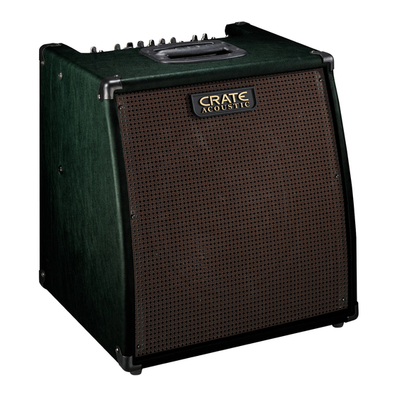
- Page 3 About the Crate Acoustic CA120D: esigned for the performing artist, Crate’s CA120D Acoustic Amplifier gives you more of what you want. More power. More clarity. More control. And, more freedom. Imagine: microphone quality sound, without feedback. And without being “chained” to a mic stand! More power: a 120 watt RMS power ampli- fier drives a Studio Monitor-style 12”...
-
Page 4: The Front Panel
The Front Panel: NOTE: Channel 1 and Channel 2 are independent of each other up to the Effects and Master sections. The text below (#1–10) applies to both channels. 1: Low-Z. The signal from a low impedance microphone may be con- nected here by means of a shielded, balanced microphone cable ter- minated with an XLR connector. -
Page 5: The Rear Panel
The Rear Panel: 19: Power. Use this switch to turn the amplifier on (top of the switch depressed) and off (bottom of the switch depressed.) The power switch illuminates when the amplifier is on. 20: AC Line Cord. The grounded power cord should only be plugged into a grounded power outlet that meets all applicable electrical codes and is compatible with the voltage, power and frequency requirements stated on the rear panel. -
Page 6: To Eliminate Instrument Feedback
To Eliminate Instrument Feedback: One of the most common problems encountered when amplifying acoustic instruments, especially in small environments, is feedback. Acoustic instruments typically have inherent qualities which cause reso- nant feedback at specific frequencies. Instrument tone controls and sound board equalizers are helpful in getting rid of the problem, but they typi- cally operate around relatively wide frequency bands. -
Page 7: System Block Diagram
System Block Diagram: Channels 1 and 2: phantom power low-z gain high-z gain aux in/ eff ret limiter level *NOTE: Feedback circuit activated when footswitch plug is inserted into Feedback Filters Footswitch jack CA120D Acoustic Amplifier peak tones DSP/eff send low mid cntr high mode... -
Page 8: Technical Specifications
Technical Specifications: Output Power Rating: Channels 1 & 2: Low: Mid: High: Input Impedance: Input Sensitivity: Sens. to Eff Send/Line out: Max Input Signal: CD Input: Input Impedance: Input Sensitivity: Max Input Signal: AuxEff. Return: Input Impedance: Input Sensitivity: Max Input Signal: Eff Send Out.
Need help?
Do you have a question about the Acoustic CA120D and is the answer not in the manual?
Questions and answers