
Subscribe to Our Youtube Channel
Related Manuals for GBT FP-2065-1-DOOR-2


Summary of Contents for GBT FP-2065-1-DOOR-2
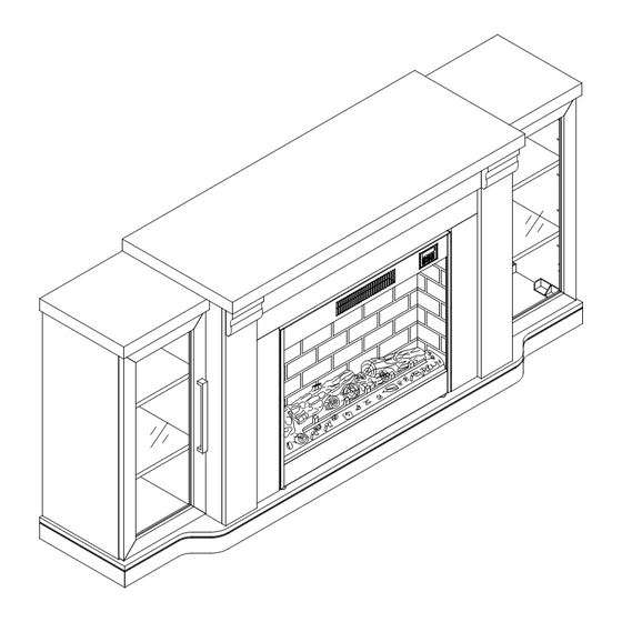
- Page 1 ASSEMBLY INSTRUCTION SHEET ITEM# FP-2065-1-DOOR-2 SKU# 810469914 DESCRIPTION: 75IN BROWN TIERED FIREPLACE CUSOTMER SERVICE NO.: 1-888-878-8820 Email:customerservice@gbtcorporation.com...
-
Page 2: Care Instructions
Warning: 1. Need at least two adults to assemble this fireplace. 2. Assemble on soft , smooth surface to protect finish from being scratched . 3. DO NOT use power tools. 4. Remove all packaging material, make sure all parts are present before assembly. - Page 3 50 " TRENDEX CO., LTD FP-2065-1-DOOR-2; VIETNAM 2020.04...
-
Page 4: Parts List
PARTS LIST BASE 1pc MIDDLE TOP PANEL LEFT TOP PANEL RIGHT TOP PANEL LEFT SIDE PANEL FRONT PANEL RIGHT SIDE PANEL RIGHT PARTITION LEFT PARTITION LEFT POST RIGHT SIDE RAIL RIGHT POST LEFT SIDE RAIL LEFT DOOR... -
Page 5: Right Door
PARTS LIST RIGHT DOOR 2pcs BACK PANEL ELECTRIC FIREPLACE INSERT 4pcs SMALL SHELF... -
Page 6: Round Head Screw
ASSEMBLY INSTRUCTION 6pcs LONG BOLT Ø1/4*2-1/4" MIDDLE BOLT Ø1/4*1-1/2" 4pcs SHORT BOLT Ø1/4*1" 6pcs SHORT BOLT Ø1/4*5/8" 36pcs SPRING Ø1/4 52pcs WASHER Ø1/4*16mm FLAT WASHER 52pcs ALLEN WRENCH 6pcs Ø1/4 18pcs BRACKET ROUND HEAD 6pcs Ø8*12mm SCREW FLAT HEAD SCREW 24pcs Ø6*15mm ROUND HEAD... - Page 7 ASSEMBLY INSTRUCTION Step 1 Place Left Side Panel (F) face down on a smooth soft surface. The side with the most holes should be facing up. Align the holes of Bracket (H9) with the holes of Left Side Panel (F) with the tenons facing outward as shown in figure 1. Secure the Bracket (H9) to the Left Side Panel (F) with Flat Washer (H6), Spring Washer (H5), and Short Bolt (H4) using Allen Wrench (H7).
- Page 8 ASSEMBLY INSTRUCTION Step 2 Place Left Post (J) on a soft smooth surface. With assistance from another adult, slide Left Partition (H) into the groove of Left Post (J) until both ends are flush. Secure the Left Partition (H) to Left Post (J) with Flat Washer (H6), Spring Washer (H5) and Short Bolt (H4) using Allen Wrench (H7).
- Page 9 ASSEMBLY INSTRUCTION Step 3 With assistance from another adult, insert tenons of Left Partition (H) and Left Side Rail (M) into the corresponding holes of Base (B). Panels may need to be slightly adjusted to be inserted into the proper holes, then place the Nut (H8) into the corresponding holes as shown in figure 3.
- Page 10 ASSEMBLY INSTRUCTION Step 4 With assistance from another adult, place the Front Panel (E) onto the tenons of Left Side Rail (M) and Right Side Rail (L). Secure the Front Panel (E) to Left Post (J) and Right Post (K) with Middle Bolt (H3), Spring Washer (H5), Flat Washer (H6) using Allen Wrench (H7) as shown in figure 4.
- Page 11 ASSEMBLY INSTRUCTION Step 5 With assistance from another adult, insert the tenons of Left Side Panel (F) and Right Side Panel (G) into the corresponding holes of Base (B). Panels may need to be slightly adjusted to be inserted into the proper holes.
- Page 12 ASSEMBLY INSTRUCTION Step 6 With assistance from another adult, insert the tenons of the Left Top Panel (C) into the corresponding holes of the Left Partition (H), then insert the tenons of the Left Side Panel (F) into the corresponding holes of Left Top Panel (C), Secure Left Top Panel (C) to Left Partition (H) with Middle Bolt (H2), Spring Washer (H5), Flat Washer (H6) using Allen Wrench (H7), and secure Left Top Panel (C) to Left Side Panel (F) with Short Bolt (H4), Spring Washer (H5), Flat Washer (H6) using Allen Wrench (H7) as shown in figure 6.
- Page 13 ASSEMBLY INSTRUCTION Step 7 With assistance from another adult, align Middle Top Panel (A) with the corresponding tennons of Front Panel (E), Left Partition (H) and Right Partition (I) and carefully lower into place. Take care not to pinch your fingers. Secure Middle Top Panel (A) to Front Panel (E), Left Partition (H) and Right Partition (I) with Short Bolt (H4), Spring Washer (H5) and Flat Washer (H6) using Allen Wrench (H7) as shown in figure 7.
- Page 14 ASSEMBLY INSTRUCTION Step 8 Inset Shelf Pin (H13) into the Left Side Panel (F), Right Side Panel (G), Left Partition (H) and Right Partition (I). To adjust the level of the shelf, move all Shelf Pin (H13) up or down as need dictates. Insert Small Shelf (Q) at an angle with the finished edge facing the front of the Mantel.
- Page 15 ASSEMBLY INSTRUCTION Step 9 With assistance from another adult, Attach Back Panel (P) to the back of the Mantel with Round Head Screw (H12) and screwdriver (not provided) as shown in figure 9. Make sure the smooth side of Back Panel (P) faces the front of the fireplace. Not provided Figure 9...
- Page 16 ASSEMBLY INSTRUCTION Step 10 Place the Electric Fireplace Insert (R) into the assembled Mantel from the back. Adjust the Fireplace Insert (R) so the space around the rails is equal. Secure the Electric Fireplace Insert (R) to the assembled Mantel with Round Head Screws (H10) using screwdriver (not provided).
- Page 17 ASSEMBLY INSTRUCTION Step 11 Place the Left Door (N) and Right Door (O) face down on a smooth soft surface. Align the holes of Hinge (H16) with the pre-drilled holes of Left Door (N) and secure in place with Flat Head Screw (H11) using screwdriver (not provided) as shown in figure 11. Repeat this process to attach Door Hinge (H16) to Right Door (O).
- Page 18 ASSEMBLY INSTRUCTION Step 12 With assistance from another adult, hold Left Door (N) vertically and attach Handle (H14) with Small Bolt (H15) using screwdriver (not provided) and fully tighten bolts as shown in figure 12. Repeat this process to attach remaining Handle (H14) to Right Door (O). N&O Not provided Figure 12...
- Page 19 ASSEMBLY INSTRUCTION Step 13 With assistance from another adult, align the holes of Hinge (H16) on the Left Door (N) with the Punctures in Left Side Panel (F) and secure in place with Flat Head Screw (H11) using screwdriver (not provided) as shown in figure 13. Fully tighten all screws. Repeat this process to attach Right Door (O) to Right Side Panel (G).
- Page 20 ASSEMBLY INSTRUCTION Assembly is now complete. Note: Please read the operating manual for the Electric Fireplace Insert and Electric Fireplace Insert remote control before using Fireplace. PRINTED IN VIETNAM MADE IN VIETNAM...
Need help?
Do you have a question about the FP-2065-1-DOOR-2 and is the answer not in the manual?
Questions and answers