
Related Manuals for Axiometrix Solutions imc BUSDAQflex


Summary of Contents for Axiometrix Solutions imc BUSDAQflex
- Page 1 BUSDAQflex Getting Started Edition 7 - 2023-08-24 © 2023 imc Test & Measurement GmbH imc Test & Measurement GmbH • Voltastr. 5 • 13355 Berlin • Germany...
- Page 2 DEVICES\OSS" or "Products\imc DEVICEcore\OSS" or "Products\imc STUDIO\OSS". If you wish to receive a copy of the GPL sources used, please contact our Hotline. © 2023 imc Test & Measurement GmbH imc BUSDAQflex - Getting Started, Edition 7 - 2023-08-24 Page 2...
- Page 3 Notes denote useful additional information on a A reference in this document is a reference in particular topic. the text to another text passage. © 2023 imc Test & Measurement GmbH imc BUSDAQflex - Getting Started, Edition 7 - 2023-08-24 Page 3...
-
Page 4: Table Of Contents
7.5 Pin configuration of the fieldbusses ................. 38 7.5.1 CAN-Bus, CAN FD (DSUB-9) ......................... 38 7.5.2 LIN-Bus (DSUB-9) ..........................38 7.5.3 FlexRay-Bus (DSUB-9) ......................... 38 7.5.4 XCPoE (RJ45) ............................39 © 2023 imc Test & Measurement GmbH imc BUSDAQflex - Getting Started, Edition 7 - 2023-08-24 Page 4... - Page 5 7.5.5 ARINC-Bus (DSUB-15) .......................... 40 7.5.6 PROFIBUS (DSUB-9) ..........................41 7.5.7 PROFINET (RJ45) ..........................41 7.5.8 MVB-Bus (DSUB-9) ..........................41 Index ......................... 44 © 2023 imc Test & Measurement GmbH imc BUSDAQflex - Getting Started, Edition 7 - 2023-08-24 Page 5...
-
Page 6: General Introduction
Certification, current certificates and information about the imc quality system on our website: https://www.imc-tm.com/quality-assurance/. imc Warranty Subject to the general terms and conditions of imc Test & Measurement GmbH. © 2023 imc Test & Measurement GmbH imc BUSDAQflex - Getting Started, Edition 7 - 2023-08-24 Page 6... - Page 7 Products not satisfying these requirements may only be used with special approval of the regulating body in the country where operated. All lines connected to the imc BUSDAQflex devices should not be longer than 30 m and they should be shielded and the shielding must be grounded.
- Page 8 In order to comply with the value limits applicable to Class B devices according to part 15 of the FCC regulations, all signal leads connected to the imc BUSDAQflex devices must be shielded. Unless otherwise indicated, no connection leads may be long leads (< 30 m) as defined by the standard IEC 61326-1.
-
Page 9: Explanation Of Symbols
The device itself does not generate dangerous voltages. DC, Direct Current Supply of the device via a DC voltage source (in the specified voltage range) © 2023 imc Test & Measurement GmbH imc BUSDAQflex - Getting Started, Edition 7 - 2023-08-24 Page 9... -
Page 10: Last Changes In Content
PC. Thus, the first step was removed from the documentation, which presented different possibilities in Windows to determine the IP address. Technical Specs We added a general introduction to this chapter. © 2023 imc Test & Measurement GmbH imc BUSDAQflex - Getting Started, Edition 7 - 2023-08-24 Page 10... -
Page 11: Safety
The user must also ensure that any personnel assisting in the use of the imc BUSDAQflex have also read and understood the content of this document. - Page 12 Industrial safety We certify that imc BUSDAQflex in all product configuration options corresponding to this documentation conforms to the directives in the accident prevention regulations in "Electric Installations and Industrial Equipment" (DGUV Regulation 3)*. This confirmation applies exclusively to devices of the imc BUSDAQflex series, but not to all other components included in the scope of delivery.
- Page 13 Before touching the device sockets and the lines connected to them, make sure static electricity is diverted to ground. Damage arising from electrostatic discharge is not covered by the warranty. © 2023 imc Test & Measurement GmbH imc BUSDAQflex - Getting Started, Edition 7 - 2023-08-24 Page 13...
-
Page 14: Assembly And Connection
1x protective cover for the remote control socket type 0B · Getting started with imc BUSDAQflex (one copy per delivery) Note File a claim about every fault as soon as it is detected. Claims for damages can only be honored within the stated claims period. -
Page 15: Notes On Connecting
(suppression) filters connected in the middle of the supply circuit should not contain any serial inductance coils of more than 1 mH. Otherwise and extra parallel capacitor is needed. © 2023 imc Test & Measurement GmbH imc BUSDAQflex - Getting Started, Edition 7 - 2023-08-24 Page 15... - Page 16 Chapter 3 Assembly and connection 3.3.2.1 Supply of directly connected imc CANSASflex modules imc BUSDAQflex (BUSFX) is compatible with the imc CANSASflex series (CANFX), CAN-Bus based measurement technique. All modules of the flex series (CANFX and BUSFX) can be joined together mechanically and electrically by means of a latching ("click")
- Page 17 A) Power via CAN not used: no stubs, unlimited block size B) Use of Power via CAN: max. size of stub blocks (Y-type stub), according CiA® © 2023 imc Test & Measurement GmbH imc BUSDAQflex - Getting Started, Edition 7 - 2023-08-24 Page 17...
- Page 18 Automatic conclusion of measurement and data saving upon power outage imc BUSDAQflex comes with UPS-functionality to ensure the integrity of data in case of power outages. When power outage occurs, this functionality prevents loss of data and is referred to as Power Fail. If the power fails, the measurement stops automatically and the data are saved to the internal bulk memory ("μ-Disk": flash media or HDD) in sufficient time.
-
Page 19: Grounding, Shielding
If no measurement is currently running, it takes only approx. 1 sec. for the device to be deactivated. 3.3.2.6 Remote On/Off The imc BUSDAQflex can be activated and deactivated via the Control switch. When the pin Remote On/Off is connected with –Supply via a push-button switch, the device can be activated/ deactivated as with the blue LED-button. -
Page 20: Fuses (Polarity-Inversion Protection)
3.3.5 Batteries For an uninterruptable power supply (UPS) Super-Caps are used to supply the imc BUSDAQflex device. No special maintenance should be necessary. No fuses are included in the device. © 2023 imc Test & Measurement GmbH... -
Page 21: Maintenance And Servicing
No special maintenance measures are required. Corrective repair work may only be performed at factory by imc Test & Measurement GmbH. Due to the UPS function of the devices of imc BUSDAQflex series, we recommend maintenance every 2-3 years. When returning the device in connection with complaints, please include a written, outlining description of the problem, including the name and telephone number of the sender. -
Page 22: Start Of Operation Software / Firmware
The cable length between the switch and a PC or a device should be less 100 m. Use a shielded cable. If the length of 100 m is exceeded, then you have to insert another switch. © 2023 imc Test & Measurement GmbH imc BUSDAQflex - Getting Started, Edition 7 - 2023-08-24 Page 22... -
Page 23: Connecting Via Lan In Three Steps
Subsequently, a prompt appears asking whether to search for devices with an inappropriately configured network interface. Close this message box by clicking "Yes". © 2023 imc Test & Measurement GmbH imc BUSDAQflex - Getting Started, Edition 7 - 2023-08-24 Page 23... - Page 24 10 . 0 . 11 . 86 Network mask 255 . 255 . 255 . 0 255 . 255 . 255 . 0 © 2023 imc Test & Measurement GmbH imc BUSDAQflex - Getting Started, Edition 7 - 2023-08-24 Page 24...
- Page 25 Now check whether the correct time zone is set for the device. For more info, see the description of the software manual under the keyword "Device properties". © 2023 imc Test & Measurement GmbH imc BUSDAQflex - Getting Started, Edition 7 - 2023-08-24 Page 25...
-
Page 26: Firmware Update
Device operating system Online Online-functions and hard drive controller Display Operating system of the connected displays Fieldbus Fieldbus interfaces (e.g. CAN etc.) Signal conditioners Amplifiers © 2023 imc Test & Measurement GmbH imc BUSDAQflex - Getting Started, Edition 7 - 2023-08-24 Page 26... - Page 27 You are notified when the firmware setup concludes successfully, as shown below: Conclusion of the firmware update (example of a single device) Choose "Close". The device can now be used with the product software. © 2023 imc Test & Measurement GmbH imc BUSDAQflex - Getting Started, Edition 7 - 2023-08-24 Page 27...
- Page 28 The function is only to be used in compliance with instructions from the imc-Hotline. © 2023 imc Test & Measurement GmbH imc BUSDAQflex - Getting Started, Edition 7 - 2023-08-24 Page 28...
-
Page 29: Introduction
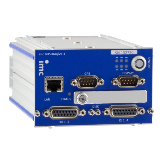
6 Introduction 6.1 imc BUSDAQflex device series imc BUSDAQflex is a series of data loggers for CAN, CAN FD, LIN, ARINC, FlexRay, XCPoE, MVB and EtherCAT. The basic configuration with default configuration with 2 CAN-nodes can be expanded to up to 12 nodes in the larger device models for various fieldbuses and vehicle buses. -
Page 30: Topology And Mounting
(LOCK). 2. In order to connect the modules correctly, the modules has to be positioned as shown in the picture above. © 2023 imc Test & Measurement GmbH imc BUSDAQflex - Getting Started, Edition 7 - 2023-08-24 Page 30... - Page 31 Contact with the magnets by food should be avoided. The magnets are protected with a coating (Ni, Au, Zn) to which some persons can have an allergic reaction Nickel allergy). © 2023 imc Test & Measurement GmbH imc BUSDAQflex - Getting Started, Edition 7 - 2023-08-24 Page 31...
-
Page 32: Can Termination
Chapter 6 Introduction 6.3 CAN Termination Each imc BUSDAQflex (BUSFX) offers 2 CAN nodes as basic equipment. The imc CANSASflex modules (CANFX), which are connected to the BUSFX device via the click connection, are located at the CAN 1 node of slot 1 (see labeling on the device, CAN 1). -
Page 33: Device Variants And Options
Device variants and options 6.4 Device variants and options © 2023 imc Test & Measurement GmbH imc BUSDAQflex - Getting Started, Edition 7 - 2023-08-24 Page 33... -
Page 34: Pin Configuration
Cable shielding must be connected at CHASSIS (DSUB frame) as a rule. At some connectors, (5 V) is available, with a maximum load current of typically 135 mA per plug. © 2023 imc Test & Measurement GmbH imc BUSDAQflex - Getting Started, Edition 7 - 2023-08-24 Page 34... -
Page 35: Metal Connector - Handling
2. Audible click when the lid snaps in the front of the DSUB pod 3. Insert the bend protection 4. The pressure nut must be screwed back on 5. The lid screws can be tightened © 2023 imc Test & Measurement GmbH imc BUSDAQflex - Getting Started, Edition 7 - 2023-08-24 Page 35... -
Page 36: Lemo.0B (6-Pin) Ctrl Socket
Pin 5. The reference of the Sleep/Resume circuit at Pin 6 is implemented by a jumper to Pin 1. © 2023 imc Test & Measurement GmbH imc BUSDAQflex - Getting Started, Edition 7 - 2023-08-24 Page 36... -
Page 37: Dsub-9 Pin Configuration
GPS 18 - 5Hz Signal Color Color RxD1* White White TxD1 Green Green GND, PowerOff 2x Black 2x Black PPS (1 Hz clock) Yellow Yellow © 2023 imc Test & Measurement GmbH imc BUSDAQflex - Getting Started, Edition 7 - 2023-08-24 Page 37... -
Page 38: Pin Configuration Of The Fieldbusses
B FlexRay ground BP channel A positive bus line channel A BP channel B positive bus line channel B © 2023 imc Test & Measurement GmbH imc BUSDAQflex - Getting Started, Edition 7 - 2023-08-24 Page 38... -
Page 39: Xcpoe (Rj45)
BP channel A (positive bus line channel A) BP channel B (positive bus line channel B) 7.5.4 XCPoE (RJ45) Standard Ethernet 1x RJ45. © 2023 imc Test & Measurement GmbH imc BUSDAQflex - Getting Started, Edition 7 - 2023-08-24 Page 39... -
Page 40: Arinc-Bus (Dsub-15)
7B Tx4B sending channel 4B Rx8A receiving channel 8A Rx8A receiving channel 8A Rx8B receiving channel 8B Rx8B receiving channel 8B © 2023 imc Test & Measurement GmbH imc BUSDAQflex - Getting Started, Edition 7 - 2023-08-24 Page 40... -
Page 41: Profibus (Dsub-9)
Terminator A internal jumper to 1 Terminator A interna jumper to 2 Terminator B interna jumper to 4 Terminator B interna jumper to 5 © 2023 imc Test & Measurement GmbH imc BUSDAQflex - Getting Started, Edition 7 - 2023-08-24 Page 41... - Page 42 Ground A B.Bus_GND Ground B A.Bus_5V 5V Supply A Rm = 143 Ω; Ru = Rd = 383 Ω B.Bus_5V 5V Supply B © 2023 imc Test & Measurement GmbH imc BUSDAQflex - Getting Started, Edition 7 - 2023-08-24 Page 42...
- Page 43 Pin configuration of the fieldbusses DSUB connection for ESD © 2023 imc Test & Measurement GmbH imc BUSDAQflex - Getting Started, Edition 7 - 2023-08-24 Page 43...
-
Page 44: Index
IP address Device configure of the devices connect of the PCs Dimension ISO-9001 DIN-EN-ISO-9001 discharge/recharge cycles Display Leads pin configuration Liability restrictions DSUB-15 © 2023 imc Test & Measurement GmbH imc BUSDAQflex - Getting Started, Edition 7 - 2023-08-24 Page 44... - Page 45 Power via CAN PROFIBUS pin configuration PROFINET pin configuration Quality Management remote control Remote: BUSLOG RoHS Service Service: Hotline shielding 19, 20 © 2023 imc Test & Measurement GmbH imc BUSDAQflex - Getting Started, Edition 7 - 2023-08-24 Page 45...
Need help?
Do you have a question about the imc BUSDAQflex and is the answer not in the manual?
Questions and answers