
Related Manuals for Axiometrix Solutions imc CAEMAX Dx


Summary of Contents for Axiometrix Solutions imc CAEMAX Dx
- Page 1 - Telemetry System Manual Edition 4 - 2023-06-05 © 2023 imc Test & Measurement GmbH imc Test & Measurement GmbH • Voltastr. 5 • 13355 Berlin • Germany...
- Page 2 Disclaimer of liability The contents of this documentation have been carefully checked for consistency with the hardware and software systems described. Nevertheless, it is impossible to completely rule out inconsistencies, so that we decline to offer any guarantee of total conformity. We reserve the right to make technical modifications of the systems.
- Page 3 Notes regarding this document This document provides important notes on using the device / the module. Safe working is conditional on compliance with all safety measures and instructions provided. The manual is to be used as a kind of reference book.
-
Page 4: Table Of Contents
Table of contents Table of contents 1 General introduction ....................6 1.1 Customer support / Hotline ......................6 1.2 Legal notice ............................. 6 1.3 Calibration of the measurement inputs ..................7 1.4 Customized cable manufacturing ....................8 1.5 Notes regarding this manual ......................8 2 Safety ........................ - Page 5 Table of contents 8.8 Commissioining with Fix stator ....................74 9 From settings to measurement ................75 9.1 Connecting the Dx-RCI receiver unit .................... 75 9.2 Connecting the Dx-SCT transmitter unit ..................77 9.3 Switching the Dx-RCI receiver unit on and off ................77 9.4 Operating the Dx-RCI ........................
-
Page 6: General Introduction
Customer support / Hotline Chapter 1 1 General introduction 1.1 Customer support / Hotline If you have problems or questions, please contact our Customer Support / Hotline. imc Test & Measurement GmbH Hotline: +49 30 467090-26 E-Mail: hotline@imc-tm.de Internet: www.imc-tm.de International partners You can find the international sales partners on the Internet at https://www.imc-tm.com/imc-worldwide/... -
Page 7: Calibration Of The Measurement Inputs
Legal notice Chapter 1 Liability restrictions All information and notes in this manual have been compiled taking into account the applicable standards and regulations, the state of the art and our many years of knowledge and experience. The manufacturer accepts no liability for damage due to: ·... -
Page 8: Customized Cable Manufacturing
Customized cable manufacturing Chapter 1 1.4 Customized cable manufacturing To comply with the limits for Class B equipment under Part 15 of the FCC Rules, all signal lines connected to the meter must be shielded and the shield must be connected. Unless otherwise indicated, all connecting cables must not be long cables as defined by IEC 61326-1 (< 30 m). -
Page 9: Safety
Chapter 2 2 Safety This section provides an overview of all important aspects of protection of the users for reliable and trouble-free operation. Failure to comply with the instructions and protection notes provided here can result in serious danger. Responsibility of the operator The D telemetry system is for use in commercial applications. - Page 10 Chapter 2 Special hazards This segment states what residual dangers have been identified by the hazard analysis. Observe the safety notes listed here and the warnings appearing in subsequent chapters of this manual in order to reduce health risks and to avoid dangerous situations.
- Page 11 Chapter 2 Observe notes and warnings Devices from imc have been carefully designed, assembled and routinely tested in accordance with the safety regulations specified in the included certificate of conformity and has left imc in perfect operating condition. To maintain this condition and to ensure continued danger-free operation, the user should pay particular attention to the remarks and warnings made in this chapter.
-
Page 12: Delivery And Operation
After unpacking Chapter 3 3 Delivery and operation 3.1 After unpacking The delivery must be checked for completeness and transport damage immediately upon receipt. In case of externally visible transport damage, proceed as follows: · Do not accept the delivery or accept it only with reservations, ·... -
Page 13: Notes On Connecting
Notes on connecting Chapter 3 3.3 Notes on connecting 3.3.1 Precautions for operation Certain ground rules for operating the system, aside from reasonable safety measures, must be observed to prevent danger to the user, third parties, the device itself and the measurement object. These are the use of the system in conformity to its design, and the refraining from altering the system, since possible later users may not be properly informed and may ill-advisedly rely on the precision and safety promised by the manufacturer. -
Page 14: Maintenance And Service
Maintenance Chapter 4 4 Maintenance and service 4.1 Maintenance No special maintenance is required. Corrective work may only be carried out by imc Test & Measurement GmbH. If you have any complaints, please enclose a note with the device containing a brief description of the fault. If the name and telephone number of the sender are also written on the note, this will help us to process the complaint quickly. -
Page 15: Introduction
Chapter 5 5 Introduction Congratulations on the purchase of your new D digital multichannel telemetry system. We recommend that you first familiarize yourself with the basics of the system before installing or commissioning it. 5.1 Abbreviation Receiver Control Interface Signal Conditioning Transmitter Receiver Satellite Unit SD-Card memory card... -
Page 16: Use
Chapter 5 5.3 Use The D telemetry system is only to be used for recording, forwarding and processing electrically measured quantities. In case of deviating use, the manufacturer does not assume any liability. The system is designed for signal processing of resistive bridges such as strain gauges, thermocouples (-200 ° C to +1000 °C) and higher level voltages (0 V to ±22 V), e.g. -
Page 17: Technical Components
Signal Conditioning Transmitter (Dx-SCT) Chapter 6 6 Technical components 6.1 Signal Conditioning Transmitter (Dx-SCT) Fig. 4: Transmit unit D -SCT -SCT 868 MHz -SCT-HT 2.4 GHz High-frequency transmitter channel freely programmable in 868 MHz channel freely programmable in ISM band 2.4 GHz ISM band Transmitting power max. - Page 18 Signal Conditioning Transmitter (Dx-SCT) Chapter 6 6.1.1 Voltage inputs for low signal levels Small signal levels, such as strain gauge bridges, active thermocouples, etc. The D -SCT transmitter unit has four inputs. In half-bridge or single-ended mode applications, all four inputs are available for measurements;...
-
Page 19: Connection Variants Of The Dx-Sct
Signal Conditioning Transmitter (Dx-SCT) Chapter 6 6.1.4 Additional channels for measurement of temperature of the transmitter electronics The additional channel for measuring the supply voltage can be used to monitor the battery voltage or the quality of the inductive supply. Measurement range -41.5 V to +41.5 V Resolution... - Page 20 Connection variants of the DX-SCT Chapter 6 Fig. 7: D -SCT with connection cable integrated in a special housing Fig. 8: D -SCT with connection cable integrated in a special housing (more detailed view) © 2023 imc Test & Measurement GmbH imc Dx - Manual, Edition 5 - 2023-06-05 Page 20...
- Page 21 Connection variants of the DX-SCT Chapter 6 Fig. 9: D -SCT with connection cable integrated in a special housing: color scheme © 2023 imc Test & Measurement GmbH imc Dx - Manual, Edition 5 - 2023-06-05 Page 21...
-
Page 22: Pin Configuration Dx-Sct
Connection variants of the DX-SCT Chapter 6 6.3 Pin configuration Dx-SCT Label Function Label Function IP1 Induktive Power 1 0.244 mV/V to 1000 mV/V freely adjustable via positive input of D -RCI if differential with I4 DC+ DC Power Plus 0.244 mV/V to 1000 mV/V freely adjustable via negative positive power supply input input of D... - Page 23 Pin configuration Dx-SCT Chapter 6 Label Function Label Function IP1 Induktive Power 1 0.244 mV/V to 1000 mV/V freely adjustable via negative input of D -RCI if differential with I3 DC+ DC Power Plus 0.244 mV/V to 1000 mV/V freely adjustable via positive positive power supply input input of D -RCI if differential connection...
- Page 24 Pin configuration Dx-SCT Chapter 6 6.3.1 Connection to a DC voltage source Fig. 10: Connection of D -SCT to a DC voltage source 6.3.2 Connection to an inductive voltage source Fig. 11: Connection of D -SCT to an inductive voltage source Reference chapter "D -OVP module"...
- Page 25 Pin configuration Dx-SCT Chapter 6 6.3.3 Resistive full bridge, e.g. strain gauge Channel 1 Channel 3 © 2023 imc Test & Measurement GmbH imc Dx - Manual, Edition 5 - 2023-06-05 Page 25...
- Page 26 Pin configuration Dx-SCT Chapter 6 6.3.4 Resistive half bridge, e.g. strain gauge Channel 1 Channel 2 © 2023 imc Test & Measurement GmbH imc Dx - Manual, Edition 5 - 2023-06-05 Page 26...
- Page 27 Pin configuration Dx-SCT Chapter 6 Channel 3 Channel 4 © 2023 imc Test & Measurement GmbH imc Dx - Manual, Edition 5 - 2023-06-05 Page 27...
- Page 28 Pin configuration Dx-SCT Chapter 6 6.3.5 Resistive quarter bridge (with completion to half bridge) : Complementary resistor with high precision and stability Channel 1 : Complementary resistor with high precision and stability Channel 2 © 2023 imc Test & Measurement GmbH imc Dx - Manual, Edition 5 - 2023-06-05 Page 28...
- Page 29 Pin configuration Dx-SCT Chapter 6 : Complementary resistor with high precision and stability Channel 3 : Complementary resistor with high precision and stability Channel 4 © 2023 imc Test & Measurement GmbH imc Dx - Manual, Edition 5 - 2023-06-05 Page 29...
- Page 30 Pin configuration Dx-SCT Chapter 6 6.3.6 Thermocouples - differential Warning Attention Thermocouples cannot be used with screw terminal or with cable housing Warning Attention For thermocouple measurements, the quality of the solder joint at the cold junction is critical. Thermocouple wires are difficult to solder.
- Page 31 Pin configuration Dx-SCT Chapter 6 6.3.7 Thermocouples - Single-ended Warning Attention This connection variant can only be used with galvanically isolated thermocouples. The differential connection is to be preferred. Warning Attention For thermocouple measurements, the quality of the solder joint at the cold junction is critical. Thermocouple wires are difficult to solder.
- Page 32 Pin configuration Dx-SCT Chapter 6 Channel 4 6.3.8 PT1000 : Complementary resistor with high precision and stability Channel 1 : Complementary resistor with high precision and stability Channel 2 © 2023 imc Test & Measurement GmbH imc Dx - Manual, Edition 5 - 2023-06-05 Page 32...
- Page 33 Pin configuration Dx-SCT Chapter 6 : Complementary resistor with high precision and stability Channel 3 : Complementary resistor with high precision and stability Channel 4 © 2023 imc Test & Measurement GmbH imc Dx - Manual, Edition 5 - 2023-06-05 Page 33...
- Page 34 Pin configuration Dx-SCT Chapter 6 6.3.9 High level voltage signal - differential 6.3.10 High level voltage signal - Single-ended © 2023 imc Test & Measurement GmbH imc Dx - Manual, Edition 5 - 2023-06-05 Page 34...
-
Page 35: Receiver Control Interface (Dx-Rci)
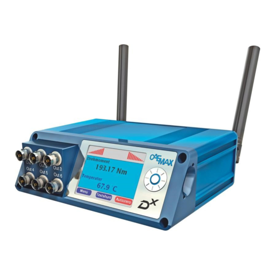
Receiver Control Interface (Dx-RCI) Chapter 6 6.4 Receiver Control Interface (Dx-RCI) Fig. 12: D -RCI front view © 2023 imc Test & Measurement GmbH imc Dx - Manual, Edition 5 - 2023-06-05 Page 35... - Page 36 Receiver Control Interface (Dx-RCI) Chapter 6 6.4.1 Technical Specs Display 2.83 Zoll IPS-Display (In-Plane Switching) Resolution 320 x 240 px Contrast high contrast, Sunlight readable Viewing angle ±85° no preferred direction Input interface multifunction wheel with rotary function and 5 keys Analog output 6 BNC sockets, freely assignable Output range...
- Page 37 Receiver Control Interface (Dx-RCI) Chapter 6 6.4.2 Sockets Fig. 13: D -RCI rear view SMA-sockets for connecting the antennas (only use the delivered rod (stick) or flat antennas) Safety sockets (banana) for the DC supply of the D -RCI (9 to 36 V) Warning Attention This connection is not suitable for supplying ring or fixed stators when an...
- Page 38 Receiver Control Interface (Dx-RCI) Chapter 6 6.4.2.1 Power socket Fig. 14: Pin configuration power socket Binder M16 (3-pin) Signal - (minus) + (plus) 6.4.2.2 CAN socket pin configuration (DSUB-9) Fig. 15: Pin configuration DSUB-9 CAN socket CiA name function n.c. CAN_L CAN_L CAN_GND...
- Page 39 Receiver Control Interface (Dx-RCI) Chapter 6 6.4.3 Synchronization To synchronize the sampling and the data stream of the D -SCT transmitters, the D -RCI receiver sends a signal every 5 ms. The maximum deviation is 60 ns. Fig. 16: Overview synchronization of multiple D -SCTs The delay between a physical event and the output on the D -RCI can be calculated with the following formulas:...
-
Page 40: Power Supply Of The Transmitter Unit Dx-Sct
Chapter 7 7 Power supply of the transmitter unit Dx-SCT Since the D -SCT transmitting unit is usually mounted on rotating components, the problem of power supply to the transmitting electronics arises. The D telemetry system offers different solutions: · supply with battery/accumulator ·... -
Page 41: Battery Supply
Battery supply Chapter 7 7.1 Battery supply The D -SCT can be operated with standard 9 V batteries or other battery types. The operating time - depending on the connected sensors and the battery used - is 3-6 h. Connect the positive and negative terminals of the battery to the DC Power Plus and DC Power Ground terminals according to the connection diagram in chapter "pin configuration Dx-SCT"... -
Page 42: Ring Stator For Inductive Power Supply
Integrated battery solutions Chapter 7 7.3 Ring stator for inductive power supply The Ring stator is used for contactless supply of the D -SCT transmitter units by inductive energy transfer: An alternating magnetic field generated by the stator ring induces a voltage in the secondary winding, which is used for the electrical supply of the D -SCT. - Page 43 Ring stator for inductive power supply Chapter 7 7.3.2 Technical Specs of the Ring stators Dimensions approx. 84 x 54 x 37 mm without copper tube and lock Tube approx. 8 mm Weight approx. 324 g without copper tube Temperature range -10 °C to +85 °C Transmission distance approx.
-
Page 44: Fixed Stator For Voltage Supply
Ring stator for inductive power supply Chapter 7 7.4 Fixed stator for voltage supply The Fixed stator is used for contactless supply of the D transmitting units D -SCTs by inductive coupling: An alternating magnetic field generated at the stator head induces a voltage in the transmission winding, which is used for electrical supply of the D transmitting unit (D -SCT). - Page 45 Fixed stator for voltage supply Chapter 7 7.4.2 Technical Specs of the fixed stator Dimensions approx. 84 x 54 x 37 mm Weight approx. 324 g Temperature range -10 °C to +85 °C Transmission distance 5 to 35 mm Power consumption max.
-
Page 46: Dx Ovp Module
Fixed stator for voltage supply Chapter 7 7.5 Dx OVP module 7.5.1 Overview The D -OVP module (Over Voltage Protection Module) is used to supply up to 4 connected D -SCT transmitting units with a constant voltage of 9 V and to protect the D -SCTs against overvoltage. - Page 47 Dx OVP module Chapter 7 7.5.4 Delivery state The D -OVP module is supplied with two short (30 cm) black cables (IP IN) for connection to the secondary winding of an inductive power supply and with two longer (100 cm) cables, red and black (DC-OUT 9 V), to which up to 4 transmitting units D -SCTs can be connected.
- Page 48 Dx OVP module Chapter 7 7.5.5 Installation Warning Only skilled personnel may carry out the installation and connect the cables. In particular, the solder pads of the D -SCTs must not be heated above 360 °C and not for too long. See also chapter "Soldering work"...
- Page 49 Dx OVP module Chapter 7 For the installation of an inductive power supply, see the relevant chapters in this document and also on the CAEMAX homepage: https://www.caemax.de/ringstator-montage/ Connection to the SCTs: · Solder the long red cable (DC-OUT 9 V) to the DC+ input of the SCT. ·...
- Page 50 Dx OVP module Chapter 7 7.5.6 Commissioning Fig. 22: Regulating the Stator power · Before commissioning, set the ring stator or fixed stator to the lowest power. To do this, use a screwdriver to turn the set screw 13 turns to the left until a click is heard. Then the ring or fixed stator is set to minimum power (see figure 21: Regulating the Stator power).
-
Page 51: Installation Of The Dx-Telemetry System
General notes Chapter 8 8 Installation of the Dx-Telemetry System 8.1 General notes · The cable connection between transmitter (sensor), transmitter unit and transducer winding should be as short as possible. · In order to obtain precise measured values, the connecting wires between sensor and transmitting unit D -SCT should be twisted in pairs, ln+ with ln- and the supply cable DC+ with DC-. -
Page 52: Installation Of The Receiver Unit Dx-Rci
Safety notes Chapter 8 8.3 Installation of the receiver unit Dx-RCI · Connect the D -RCI receiver unit to a voltage source. To do this, use the DC inputs (9 V to 36 V DC) or supply the system with the supplied power supply unit. ·... -
Page 53: Installing The Dx-Sct Transmitter Unit On A Shaft
Installation of the receiver unit Dx-RCI Chapter 8 8.4 Installing the Dx-SCT transmitter unit on a shaft After connecting the sensors to the D -SCT transmitter unit, it can be fixed on the shaft. Fig. 23: Shaft with Dx-SCT When mounting the D -SCT transmitter unit, please ensure that it lies flat on the shaft and is screwed in place. -
Page 54: Attachment Of A Secondary Winding For Inductive Energy Transfer
Attachment of a secondary winding for inductive energy transfer Chapter 8 8.5 Attachment of a secondary winding for inductive energy transfer A standard application of the D telemetry system is measurements on rotating shafts. The individual steps in mounting a secondary winding for inductive energy transfer on the shaft are shown below. The materials required for mounting can be ordered as a set from imc (Mounting Kit). - Page 55 Attachment of a secondary winding for inductive energy transfer Chapter 8 8.5.2 Step by Step guidance 1. Wrap the shaft with fabric tape. The isolated surface must be wider on both sides than the mu metal to be subsequently applied to prevent short-circuiting of the Mu metal with the shaft. Fig.
- Page 56 Attachment of a secondary winding for inductive energy transfer Chapter 8 3. Pull off the protective foil and stick the Mu metal onto the shaft. The ends must not touch, there must be no short-circuit winding with the Mu metal. Fig.
- Page 57 Attachment of a secondary winding for inductive energy transfer Chapter 8 4. Now isolate the Mu metal as described under Fig. 29: Attaching isolating tape 5. Now calculate the length of the second Mu metal layer with the formula π * diameter + 10 mm. Fig.
- Page 58 Attachment of a secondary winding for inductive energy transfer Chapter 8 7. Now the second Mu metal layer is applied. The overlap of this Mu metal layer must be offset by at least 90 ° to the overlap of the first Mu metal layer. So, for example, rotate the shaft by at least 90 ° before applying the second Mu metal layer.
- Page 59 Attachment of a secondary winding for inductive energy transfer Chapter 8 8. Apply the first layer of heat-resistant Kapton tape (polyimide tape) in the center. Fig. 33: Apply Kapton tape Fig. 34: After attaching the Kapton tape © 2023 imc Test & Measurement GmbH imc Dx - Manual, Edition 5 - 2023-06-05 Page 59...
- Page 60 Attachment of a secondary winding for inductive energy transfer Chapter 8 9. Calculate the length of the copper tape for the secondary winding using the formula π * diameter - 5 mm. Cut the copper tape to size. Fig. 35: Measuring the diameter 10.
- Page 61 Attachment of a secondary winding for inductive energy transfer Chapter 8 11. Now attach the D -SCT transmitter unit in a suitable manner. Fig. 37: Shaft with transmitter unit D -SCT, secondary winding and Ring stator 12. Measure and cut the stranded wire (at least AWG 20 or 0.62 mm ) for the inductive power supply, strip the ends and tin them.
- Page 62 Attachment of a secondary winding for inductive energy transfer Chapter 8 13. Now place the copper strip as secondary winding centrally on the polyimide layer. The distance between the copper ends must be approx. 5 mm. Note If the ends of the secondary winding (copper strip) touch, the D -SCT transmitter unit is not supplied with power.
- Page 63 Attachment of a secondary winding for inductive energy transfer Chapter 8 14. Solder the wire ends to the IP1 and IP2 terminals of the D -SCT transmitter unit. Fig. 40: Soldering the wire ends to the D -SCT transmitter unit Fig.
- Page 64 Attachment of a secondary winding for inductive energy transfer Chapter 8 15. To secure against centrifugal forces and for protection, the transformer winding must be wrapped with the supplied fabric tape. Before commissioning the system, please observe chapter "Commissioning with ring stator"...
-
Page 65: Attachment Of A Ring Stator Winding For Inductive Energy Transfer
Attachment of a secondary winding for inductive energy transfer Chapter 8 8.6 Attachment of a ring stator winding for inductive energy transfer A standard application of the D telemetry system is measurements on rotating shafts. The individual steps in mounting a secondary winding for inductive energy transfer on the shaft are shown below. The materials required for mounting can be ordered as a set from imc (Mounting Kit). - Page 66 Attachment of a ring stator winding for inductive energy transfer Chapter 8 8.6.2 Step by Step guidance 1. Calculate the length of the copper ring: (40 mm + diameter) * π + 2 * L Fig. 45: Ring stator setup 2.
- Page 67 Attachment of a ring stator winding for inductive energy transfer Chapter 8 3. … and shape the arc. Fig. 47: Form the arc of the ring stator 4. Press the copper tube together at both ends. Fig. 48: Press the copper tube together at both ends ©...
- Page 68 Attachment of a ring stator winding for inductive energy transfer Chapter 8 5. Drill a 5 mm diameter hole in each end of the copper tube. Fig. 49: Hole diameter and spacing 6. Trim the holes. Fig. 50: Trim the holes ©...
- Page 69 Attachment of a ring stator winding for inductive energy transfer Chapter 8 7. Sand the contact surfaces of the copper tube to reduce resistance. Fig. 51: Sanding contact surfaces 8. Screw the primary winding to the ring stator. Fig. 52: Screw primary winding to ring stator ©...
- Page 70 Attachment of a ring stator winding for inductive energy transfer Chapter 8 9. Important: Set the output power regulator to the minimum position by turning it counterclockwise to avoid overvoltage. Warning Attention Set the stator power to the minimum value via the potentiometer screw on the stator housing. The direction of rotation for reducing the stator power is indicated on the housing.
- Page 71 Attachment of a ring stator winding for inductive energy transfer Chapter 8 Fig. 54: Connect the power cable to the ring stator 11. Complete structure. Before commissioning the system, please refer to chapter "Commissioning with Ring stator" Fig. 55: Complete assembly: ring stator and secondary winding ©...
-
Page 72: Commissioning With Ring Stator
Attachment of a ring stator winding for inductive energy transfer Chapter 8 8.7 Commissioning with Ring stator Warning Attention Set the stator power to the minimum value via the potentiometer screw on the stator housing. The direction of rotation for reducing the stator power is indicated on the housing. When the potentiometer screw has reached the minimum position, you will hear a clicking noise when turning it further. - Page 73 Commissioning with Ring stator Chapter 8 Fig. 56: Adjusting the stator power via potentiometer screw Note For diameters of 300 mm and more, we recommend using an OVP module for overvoltage protection (see chapter "Dx-OVP module" Reference Further information on troubleshooting can be found in the "Questions &...
-
Page 74: Commissioining With Fix Stator
Commissioning with Ring stator Chapter 8 8.8 Commissioining with Fix stator · Attach the secondary winding of the inductive energy transfer to the shaft (for step-by-step instructions on how to attach the secondary winding, see the "Step-by-step instructions" chapter · Attach the Fix stator close to the shaft. -
Page 75: From Settings To Measurement
Chapter 9 9 From settings to measurement For a measurement, perform the following steps: · Connect the Dx-RCI receiver unit · Connect the transmitting unit Dx-SCT · If desired, connect a PC to the Dx-RCI · Switch on the Dx-RCI ·... - Page 76 Connecting the Dx-RCI receiver unit Chapter 9 Fig. 58: Plugged CAN terminating rsistor (120 Ω) Figure 58 shows an example of a CAN network consisting of 2 D -RCIs and a PC. The PC and the D -RCI 1 are each located at one end of the CAN bus. In the example, 120-Ω resistors must be inserted at D -RCI 1 and at the PC respectively.
-
Page 77: Connecting The Dx-Sct Transmitter Unit
Connecting the Dx-SCT transmitter unit Chapter 9 9.2 Connecting the Dx-SCT transmitter unit The D -SCT can be supplied with power by battery or rechargeable battery or inductively with ring stator or fixed stator. For connecting the voltage source, please refer to chapter: Dx-SCT connection variants Note To check whether the voltage you have applied is sufficient to operate the Dx-SCT transmitter unit, check the... - Page 78 Parameterization at the PC Chapter 9 To open the configuration dialog for a direct connection, use one of the following: · · Open Windows' input box by using the keyboard Open the Windows Settings and search for "View combination network connections" [Win+R] ·...
- Page 79 Parameterization at the PC Chapter 9 Fig. 62: D -Start menu Now you can perform the configuration via your web browser. Note The following steps (Integrate new Dx-SCT transmitter unit start measurement ) can be performed both on the D -RCI receiver unit and via your web browser.
-
Page 80: Integrating New Dx-Sct Transmitter Unit
Parameterization at the PC Chapter 9 9.6 Integrating new Dx-SCT transmitter unit 9.6.1 Add a new Device A device is already present as the default setting. However, if this is deleted or if you require further devices for further D -SCTs, then switch on the/one new D -SCT transmitter unit to connect it to the D -RCI receiver unit. - Page 81 Integrating new Dx-SCT transmitter unit Chapter 9 The frequency of the D -RCI must match the frequency of the D -SCT. Keep the following in mind: Let's assume you have saved your settings in a DXP file. Now you change the frequency of the D -SCT and the D -RCI and reprogram them.
- Page 82 Integrating new Dx-SCT transmitter unit Chapter 9 A search window appears. If the D -SCT is found, the version and the logical number are read out and a pop-up window appears. Confirm the Device found! message with OK. Fig. 65: Message "Device found!" If the D -RCI does not find the D -SCT, the frequencies of the D...
- Page 83 Integrating new Dx-SCT transmitter unit Chapter 9 If you operate two transmitting units D -SCTs, use the Logical Number 1 for one D -SCT and the Logical Number 3 for the second. Thus, each D -SCT has 2/4 of the transmission time available. For 3 and 4 D -SCT units, you can distribute the numbers as you wish.
- Page 84 Integrating new Dx-SCT transmitter unit Chapter 9 If you configure via the PC, confirm your entries with Set. Click on the Program button The following instruction appear Program done! Repower transmitter! Fig. 67: Message "Program done!" Confirm with OK. Warning Attention The message Program done! only indicates that the configuration data has been sent.
-
Page 85: Channel Configuration
Channel configuration Chapter 9 9.7 Channel configuration If you have newly integrated one or more D -SCT transmitting units, all desired channels must be created and set in the next step. When this has been done, the settings must be saved in the DXP file (see chapter "Save configuration"... - Page 86 Channel configuration Chapter 9 · PT signal (on Channel 1, 2, 3 and 4, and on those channels only this) Channels 7 and 8 record the reference temperature and supply voltage of the D -SCT. These are sampled at 25 Hz and do not load the bandwidth. Fig.
- Page 87 Channel configuration Chapter 9 9.7.2 Program channels After each integration of a new D -SCT transmitter unit, an associated channel must be reprogrammed by each -SCT. To create a new channel, please refer to chapter "Assigning channels" Open the menu item Channels → Device X → Channel X_Y. Device X here is the newly integrated D -SCT transmitter unit.
- Page 88 Channel configuration Chapter 9 9.7.3 Configure full and half bridge First make sure that the respective channel is defined as a bridge input (see chapter "Assigning channels" Open the desired channel with Channels→(Device X)→Channel X. 9.7.3.1 Calibration Enter the coordinates of your calibration lines in the Calibration section under Sample 1: and Sample 2:. In the Units: field, specify the physical unit of the output quantity.
- Page 89 Channel configuration Chapter 9 Example 1 Strain gauge full bridge Let the following calibration line be given: Fig. 71: Example of a calbration table Enter the physical quantity in the field Units, in the example "Nm". Now take two points from the calibration line, e.g.: (-1000 Nm, -4 mV/V) and (1000 Nm, 4 mV/V).
- Page 90 Channel configuration Chapter 9 Example 2 Strain gauge full bridge Let the following sensitivity be given (taken from the calibration record): In the example, the sensitivity is 3.1175 mV/V /kNm. 0 [mv/V] should correspond to 0 [kNm], and 3.1175 [mV/V] then correspond to 1 [kNm] with the example values. The values are then entered as follows: ·...
- Page 91 Channel configuration Chapter 9 Example 2 Continued example 2: Strain gauge full bridge For orientation, you can also use the measured values from the calibration certificate (here an example screenshot): We have entered that 3.1175 mV/V corresponds to one kNm. For 2 kNm, we would expect a value of approx. 6.23 mV/V, which corresponds well with the corresponding values (6.226106, ...) from the calibration certificate.
- Page 92 Channel configuration Chapter 9 9.7.3.2 Measurement range Enter the lower/upper limit of the measuring range in the specified unit under Range min: and Range max:. This is resolved with 16 bits. The next possible enclosing range is selected. Note The measuring range is adjustable in powers of two symmetrically around the zero point. When configuring via a web browser, click Set to apply the settings.
- Page 93 Channel configuration Chapter 9 9.7.3.3 Autozero To be able to perform a zero adjustment for this channel in the measurement mode, check Autozero (in an Autozero, the electrical quantity is set to zero, not the quantity converted with the straight line). When configuring via a web browser, click Set to apply the settings.
- Page 94 Channel configuration Chapter 9 In the Program done! window, confirm with OK. Fig. 74: Configuration menu thermocouple 9.7.5 Inputs for high-level voltage signal configuration Open the desired channel with Channels→(Device X)→Channel X. 9.7.5.1 Calibration Enter the coordinates of your calibration lines in the Calibration section under Sample 1: and Sample 2:. In the Units: field, specify the physical unit of the output quantity.
- Page 95 Channel configuration Chapter 9 9.7.5.3 Measurement range Enter the lower/upper limit of the measurement range in the specified unit under Range min: and Range max:. This is resolved with 16 bits. Note The measurement range is adjustable in powers of two symmetrically around the zero point. When configuring via a web browser, click Set to apply the settings.
- Page 96 Channel configuration Chapter 9 9.7.6 Version "3 Full-Br/Th": Configure third full bridge The option to use a third full bridge is only available with a D -SCT of version "3 Full-Br/Th". Search for the desired D -SCT transmitter unit as described in chapter "Creating a new transmitter unit"...
- Page 97 Channel configuration Chapter 9 · Under Resource Usage (Channels→(Device X)→Modes), set Channel 5 to Full bridge. Fig. 77: Set channel 5 to Full bridge © 2023 imc Test & Measurement GmbH imc Dx - Manual, Edition 5 - 2023-06-05 Page 97...
- Page 98 Channel configuration Chapter 9 · Select Channels ->(Device X)→ Channel 5. Fig. 78: Configuration menu for one full bridge Enter the coordinates of your calibration lines in the Calibration section under Sample 1: and Sample 2:. In the Units: field, specify the physical unit of the output quantity. Enter the lower/upper limit of the measurement range in the specified unit for each channel under Range min: and Range max:.
- Page 99 Channel configuration Chapter 9 9.7.7 Version "with RPM-Opt.": Configure RPM signal This option is only available with a D -SCT of the version "with RPM-Opt..". Search for the desired D -SCT transmitter unit as described in chapter "Creating a new transmitter unit" ·...
- Page 100 Channel configuration Chapter 9 Set the Channel 5 to RPM signal under Resource Usage (Channels→(Device X)→Modes). Fig. 80: Set channel 5 to RPM signal © 2023 imc Test & Measurement GmbH imc Dx - Manual, Edition 5 - 2023-06-05 Page 100...
- Page 101 Channel configuration Chapter 9 Select Channels ->(Device X)→ Channel 5. Fig. 81: Configuration menu for channel 5 with RPM signal Enter the coordinates of your calibration lines in the Calibration section under Sample 1: and Sample 2:. In the Units: field, specify the physical unit of the output quantity. ©...
- Page 102 Channel configuration Chapter 9 Example Convert RPM to RPS Let's assume you have connected the D -Speed rotation rate sensor. This supplies the rotation rate in revolutions per minute on channel 5. However, you want to display the rotation rate in revolutions per second. In the Units: field, enter the physical quantity you want to obtain, in this case rps (revolutions per second).
- Page 103 Channel configuration Chapter 9 9.7.8 Version "3 ext. Thermo": Configure thermo signal This option is only available with a D -SCT of the "3 ext. Thermo" version. Selected external amplifiers can be connected to this version, with which a sensor break can be detected. Search for the desired D -SCT transmitter unit as described in chapter "Creating a new transmitter unit"...
- Page 104 Channel configuration Chapter 9 Under Resource Usage (Channels→(Device X)→Modes), set Channel 4 and/or 5 and/or 6 to Thermo signal. Fig. 83: Set channels to thermo signal Select the channels you just set to Thermo signal (Channels→(Device X)→Channel_X) one by one. ©...
- Page 105 Channel configuration Chapter 9 Fig. 84: Configuration menu for channels with Thermo signal Enter the coordinates of your calibration line in the Calibration section under Sample 1: and Sample 2:. When entering under [V], you must subtract an offset of 2.048 V from the value from the calibration sheet and then enter the resulting value.
- Page 106 Channel configuration Chapter 9 9.7.9 Version "with PT-Opt.": PT-Signal konfigurieren This option is only available with a D -SCT of the "with PT-Opt." version. Search for the desired Dx-SCT transmitter unit as described in chapter "Creating a new transmitter unit" If the D -SCT is found, "with PT-Opt."...
- Page 107 Channel configuration Chapter 9 Under Resource Usage (Channels→(Device X)→Modes), set Channel 1 and/or 2 and/or 3 and/or 4 to PT signal. Fig. 86: Set channels to PT signal © 2023 imc Test & Measurement GmbH imc Dx - Manual, Edition 5 - 2023-06-05 Page 107...
- Page 108 Channel configuration Chapter 9 Select the channels you just set to PT signal (Channels→(Device X)→Channel_X) one by one. Fig. 87: Configuration menu for channels with Thermo signal Enter the coordinates of your calibration lines in the Calibration section under Sample 1: and Sample 2:. In the Units: field, specify the physical unit of the output quantity.
- Page 109 Channel configuration Chapter 9 9.7.10 Autozero 9.7.10.1 Set Autozero Open the desired channel with Channels→(Device X)→Channel X. To be able to perform a zero adjustment for this channel in the measuring mode, set a check mark at Autozero. This is the default setting. Fig.
- Page 110 Channel configuration Chapter 9 To do that press the Autozero button. Wait until the process is completed. The measured variable must be stable during the adjustment process. The channels that do not have the Autozero checkmark remain unchanged. Fig. 89: Trigger Autozero during measurement Note The measured variable must be stable during the adjustment process.
- Page 111 Channel configuration Chapter 9 If the adjustment is to remain permanently stored in the D -SCT transmitter unit, the corresponding channel must be programmed after the zero adjustment (Channels→(Device X)→Channel X → Program). Fig. 90: Program channel Note The zero adjustment can be permanently stored in the D -SCT by programming any channel of the D -SCT.
- Page 112 Channel configuration Chapter 9 9.7.10.2 Cancel Autozero To delete a stored zero balance value again, open the desired channel with Channels→(Device X)→Channel X. Remove the check mark from Autozero. Fig. 91: Remove checkmark from Autozero When configuring via a web browser, click Set to apply the settings. Now reprogram the channel with Channels→(Device X)→Channel X →...
- Page 113 Channel configuration Chapter 9 Fig. 92: Program channels Now the previously saved adjustment is canceled again. If you want to trigger an autozero again, open the desired channel with Channels→(Device X)→Channel X. Now check the Autozero box again. Note To delete a stored zero balance value again, remove the check mark from Autozero and reprogram the channel.
- Page 114 Channel configuration Chapter 9 9.7.11 Set sampling rate Each channel of the D telemetry system is assigned the same sampling rate (except for the additional channels Reference Temp. and Supply Voltage). If you want to change the sampling rate of the D telemetry system, each D -SCT transmitter unit must be reprogrammed individually.
- Page 115 Channel configuration Chapter 9 For example: When configuring 2 D -SCT 868 MHz transmitting units, the first D -SCT is assigned 3 channels, the second only 1 channel. The higher number is decisive. This results in a maximum sampling rate of 1200 Hz. When configuring via a web browser, click Set to apply the settings.
- Page 116 Channel configuration Chapter 9 9.7.12 Save settings in DXP file and program Dx-SCT When you have made all the settings, save them in the DXP file under Load/Save (cf. chapter "Save configuration" ). You must then program any channel of the D -SCT to send the settings to the D -SCT.
-
Page 117: Configure Analog Outputs
Configure analog outputs Chapter 9 9.8 Configure analog outputs The 6 analog outputs of the D telemetry system are freely assignable to all measuring channels. In the menu, choose Outputs → Output X. Fig. 96: Configuration menu analog output Under Source:, select the data channel that you want to output. If you check min /max = -10 V to +10 V, the lower/upper limit of the measurement range (see chapter "Measurement range"... - Page 118 Configure CAN output Chapter 9 9.9.1 Create/remove CAN message In the menu, select CAN Setup → New Msg. Enter the desired CAN-Id of the message in decimal or hexadecimal at Id:. With a check mark at hex you switch the CAN-Id from decimal to hexadecimal. Set a check mark in the field active, so that this message is sent in measurement mode.
- Page 119 Configure CAN output Chapter 9 9.9.2 Change/save CAN settings 9.9.2.1 CAN bus settings In the menu, select CAN Setup → General. Under Bitrate: select the bitrate of the CAN bus (default setting 500 kBaud). With a check mark at Extended Identifier you use a 29-bit identifier, without a check mark the default identifier with 11 bit is used. Check Ignore Acknowledge to disable the acknowledge function when sending each CAN message.
- Page 120 Configure CAN output Chapter 9 9.9.2.3 Download DBC file To download the DBC file from the D -RCI receiver unit to the measuring computer via a network connection, select the Download menu item in the browser. Note This menu item is only displayed in your browser and not on the D -RCI receiver unit.
-
Page 121: Configure Online Display
Configure CAN output Chapter 9 9.10 Configure Online display In the measuring mode, you can have the current measured values output numerically on the display. You can configure up to 5 windows for this purpose. In the Measure menu item, select the Display X subitem. Select the channels you want to display from the drop-down menu. -
Page 122: Save And Load Settings
Configure Online display Chapter 9 9.11 Save and load settings You can store your configuration in a DXP file on the SD card. When the file is called up, the configuration data is read in and the system is parameterized accordingly. When the D -RCI receiver unit is restarted, the DEFAULT.dxp configuration file is always read in. - Page 123 Save and load settings Chapter 9 9.11.2 Load configuration Select the Load/Save menu item. Under File Name, select or enter the file name of the configuration file from the drop-down list. Select the Load button. Confirm the Parameters loaded! message with OK. Warning Attention The frequency of a D...
- Page 124 Save and load settings Chapter 9 9.11.4 Call configuration file automatically at program start When the D -RCI is restarted, the configuration file DEFAULT.dxp is always read in. If you save your configuration under this file name, it will be available immediately after switching on. Select the Load/Save menu item.
-
Page 125: Start Measurement
Save and load settings Chapter 9 9.12 Start measurement 9.12.1 Measurement and configurations mode The switched-on D -RCI receiver unit is always in one of two modes: · In measurement mode (Measure → Start), data is processed and transmitted to the CAN bus. ·... - Page 126 Start measurement Chapter 9 9.12.2.4 Stop measurement To exit the measurement mode, press the Cancel button on the D -RCI receiver unit. You can cancel the measurement via the web browser by clicking on any menu item. Fig. 102: Measurement mode ©...
- Page 127 Start measurement Chapter 9 9.12.3 Start measurement automatically when switching on (Auto Measure Start) With this function, the D -RCI receiver unit immediately goes into measurement mode after being switched on. The measurement does not have to be started manually separately. This function only makes sense in connection with the Default.dxp file, since this file is automatically loaded when the D -RCI is started (if it exists).
-
Page 128: Dx Configuration Menu: Reference
Chapter 10 10 Dx Configuration menu: Reference In this section all functions of the D configuration menu are shown in detail. 10.1 Menu tree © 2023 imc Test & Measurement GmbH imc Dx - Manual, Edition 5 - 2023-06-05 Page 128... -
Page 129: Settings
Settings Chapter 10 10.2 Settings 10.2.1 Menu: Device - Base RCI Version: Information on the D -RCI version Radio Frequency: Here you can set the desired radio frequency via a drop-down menu. To change the frequency, the Program button must be pressed after setting the frequency. If you use several D -RCI receiver units within radio range, they must be programmed with different frequencies. - Page 130 Settings Chapter 10 Program: Adopt the set parameters: Programs the frequency of the transceivers of the D -RCI or the connected satellites. Exit menu item Warning Attention For a permanent change of the settings, the configuration must be saved via the Load/Save menu item (exception: the setting of the frequency.
- Page 131 Settings Chapter 10 10.2.2 Menu: Device - Device1 Serial Number: This number is used to address the D -SCT transmitter unit to be programmed. Only this D SCT is addressed when programming the frequency and the logical number. Search: This function searches for a D -SCT transmitting unit on the respective frequency and determines the Serial Number and Logical Number and enters them in the mask.
- Page 132 Settings Chapter 10 Logical Number: This number defines the starting point of the data transmission of the respective transmitting unit D -SCT in the transmission window. The time range is divided into 4 sections ("Logical Number" 1-4). If you use only one D -SCT transmitting unit, use the "Logical Number"...
- Page 133 Settings Chapter 10 10.2.4 Menu: Channels - Modes 10.2.4.1 Standard version Channel 1: Select the measuring mode for the channel here. The following settings are available in the standard version: · Full bridge: full bridge strain gauge · Half bridge: half bridge strain gauge with integrated completion ·...
- Page 134 Settings Chapter 10 Warning Attention For a permanent change of the settings, the configuration must be saved on the SD in the D -RCI via the Load/Save menu item. If a change is made, one channel of the D -SCT must be programmed. If the sampling rate changes, all D -SCTs of the system must be reprogrammed.
- Page 135 Settings Chapter 10 10.2.4.5 Version "with PT-Opt." Channel 1: Select whether to enable the "Channel 1" "PT signal". Channel 2: Select whether the "Channel 2" "PT signal" should be activated. Channel 3: Select if the "Channel 3" "PT signal" should be activated Channel 4: Select whether the "Channel 4"...
- Page 136 Settings Chapter 10 10.2.5 Menu: Channels - Channel x Name: Enter a channel name with a maximum of 16 letters here. Units phys.: Here you enter the desired physical unit. Sample 1: Sample 1 and Sample 2 define a calibration line which determines the conversion of the electrical signal (e.g.
- Page 137 Settings Chapter 10 10.2.6 Menu: Outputs - Output x Source: Selection of the channel that is to be output in analog form min/max: If this check mark is set, the maximum measurement range of the channel is converted into an analog signal from -10 V to +10 V. If it is not set, the output range can be defined by a two-point calibration.
- Page 138 Settings Chapter 10 10.2.7 Menu: CAN-Setup - General Bitrate: Setting the transmission rate for the CAN bus Extended Identifier:If this option is enabled, a 29-bit extended identifier is used, otherwise the 11-bit. Ignore The D -RCI receiver unit sends data without waiting for an acknowledgment of receipt from Acknowledge: another bus station.
- Page 139 Settings Chapter 10 10.2.8 Menu: CAN-Setup - Rem. Ctrl This function allows other devices to remotely activate the "Autozero" function or the "Test Shunt" on your D system. Enter here the desired CAN-Id for the "Autozero Message" in decimal or hexadecimal. (Autozero Message) Enter here the desired CAN-Id for the "Shunt Message"...
- Page 140 Settings Chapter 10 10.2.9 Menu: CAN-Setup - Message x Enter here the desired CAN-Id of the message in decimal or hexadecimal. hex: Switching the CAN-Id from decimal to hexadecimal active: Activate the message. Only if this box is selected, the message is sent via the CAN bus. However, it is also written to the DBC file in the non-activated state.
- Page 141 Settings Chapter 10 10.2.10 Menu: CAN-Setup - New Msg. If you want to use more than one CAN message, each with max. 4 channels, additional messages can be parameterized. With the menu command "CAN-Setup -> New Msg." you can easily add a new message. Warning Attention ·...
- Page 142 Settings Chapter 10 10.2.12 Menu: Measure - Display x 1-8: In lines 1 to 8, you select the channel to be shown on this display. Furthermore, the maximum number of characters (including sign, comma and decimal places) as well as the decimal places can be specified.
- Page 143 Settings Chapter 10 10.2.13 Menu: Measure - Start Indication of which display you are in. The input wheel can be used to switch a display back and forth by pushing the push button up or down. dbm display: The display of the reception quality as a bar graph or as a decimal number. See "Options ->...
- Page 144 Settings Chapter 10 10.2.14 Menu: Options Screen Saver The time in seconds after which the screen saver is turned on. Timeout: Date: Enter the date in the format: mm/dd/yyyy. Time: Enter the time in the format: hh:mm:ss Auto Measure If this function is activated, the measuring mode with the CAN output is started Start: automatically after the D -RCI receiver unit is switched on.
- Page 145 Settings Chapter 10 10.2.15 Menu: Load/Save This affects the files on the SD card. File Name: Selection of the file name of the DXP file to be loaded or saved. The parameter file "DEFAULT.dxp" is loaded automatically at startup. Existing file names can be selected or new names can be entered.
- Page 146 Settings Chapter 10 10.2.16 Upload via Ethernet connection If there is an Ethernet connection to your D telemetry system, you can conveniently upload files, for example for a firmware update, using the upload function of your browser. To do this, open a web browser and call up the IP address of the D -RCI (see also chapter "Parameterization on the PC"...
-
Page 147: Dx Special Systems
Dx-Speed: Rotational speed measurement Chapter 11 11 Dx Special Systems 11.1 Dx-Speed: Rotational speed measurement 11.1.1 System overview Your system consists of a D -Speed sensor, the D -SCT transmitter unit modified for this purpose and a D -RCI receiver unit. imc supplies the system in half-shell housings, round housings or manufactures individual solutions according to customer requirements. - Page 148 Dx-Speed: Rotational speed measurement Chapter 11 · Set Channel 5 to RPM signal under Resource Usage (see chapter "Channel configuration" Fig. 106: Set channel 5 to RPM signal · Select Channels -> Channel 5 and program it (see chapter "Programming channels" ·...
-
Page 149: Dx-Power: Mechanical Power Measurements
Dx-Speed: Rotational speed measurement Chapter 11 11.2 Dx-Power: Mechanical power measurements 11.2.1 System overview Your system consists of a D -Speed sensor, a strain gauge for measuring torque, a modified D -SCT transmitter unit and a D -RCI receiver unit. From the values of the D -Speed sensor and the corresponding torque measuring point, the D -RCI calculates the mechanical power according to the formula 2π... - Page 150 Dx-Power: Mechanical power measurements Chapter 11 11.2.3 Settings Perform the settings for the D -Speed as described in chapter "Settings" · Under Resource Usage, set Channel 1 to Full bridge and Channel 5 to RPM signal (see chapter "Channel configuration" Fig.
- Page 151 Dx-Power: Mechanical power measurements Chapter 11 · Under Local Channel Selection, set Power 1 to the channel that supplies the torque value (in the example "Torque") Fig. 110: Set Power 1 to the channel coupled with the torque · Set up a display window via Measure -> Display_X (see chapter "Configuring the online display"...
-
Page 152: Dx-Braketemp: Temperature Measurement At The Brake Disc
Dx-Power: Mechanical power measurements Chapter 11 11.3 Dx-BrakeTemp: Temperature measurement at the brake disc 11.3.1 System overview Your system consists of one or two transmitter units D -SCT modified for this purpose as well as a receiver unit -RCI and a round housing with 2, 3, 4 or 6 thermocouple sockets. On request imc also supplies the necessary impact sensors for temperature measurement. - Page 153 Dx-BrakeTemp: Temperature measurement at the brake disc Chapter 11 Go to the menu Resource Usage under Channels->(Device X)->Modes Fig. 113: On the Way to Resource Usage Under Resource Usage, set Channel 1, 3 and 5 to Thermo diff. Fig. 114: Channel settings with 3 thermocouples Select Channels ->...
- Page 154 Dx-BrakeTemp: Temperature measurement at the brake disc Chapter 11 Select the desired display by pressing the top/bottom of the scroll wheel (the current display number is in the top left corner). The temperatures are displayed. Fig. 115: Display of the temperatures (example picture) ©...
-
Page 155: Accessories
Dx antennas Chapter 12 12 Accessories 12.1 Dx antennas A number of antenna types are available for interference-free signal transmission in a wide variety of applications. 12.1.1 Flat antenna · Cable length approx. 5 m (optional 7..10 m), SMA plug · Universal mounting options ·... -
Page 156: Dx Satellite Receiver (Dx-Rsu)
Dx antennas Chapter 12 12.1.2 Side mirror antenna For driving tests in public road traffic, the measuring system should be set up as inconspicuously as possible. The antenna can be easily and quickly attached to the side exterior mirrors of the vehicle with the supplied rubber band mount. - Page 157 Dx satellite receiver (Dx-RSU) Chapter 12 Fig. 118: D satellite antenna Fig. 119: D RSU Y-cable to connect multiple D satellite antennas © 2023 imc Test & Measurement GmbH imc Dx - Manual, Edition 5 - 2023-06-05 Page 157...
-
Page 158: Questions & Answers
No signal from transmitting unit Dx-SCT: Automatic search Chapter 13 13 Questions & Answers 13.1 No signal from transmitting unit Dx-SCT: Automatic search imc's D Frequency Lookup Tool allows you to automatically search for a D -SCT that is ready to transmit. You can download the program here ©... -
Page 159: No Signal From Dx-Sct Transmitter Unit: Troubleshooting
No signal from Dx-SCT transmitter unit: Troubleshooting Chapter 13 13.2 No signal from Dx-SCT transmitter unit: Troubleshooting © 2023 imc Test & Measurement GmbH imc Dx - Manual, Edition 5 - 2023-06-05 Page 159... - Page 160 No signal from Dx-SCT transmitter unit: Troubleshooting Chapter 13 © 2023 imc Test & Measurement GmbH imc Dx - Manual, Edition 5 - 2023-06-05 Page 160...
- Page 161 No signal from Dx-SCT transmitter unit: Troubleshooting Chapter 13 © 2023 imc Test & Measurement GmbH imc Dx - Manual, Edition 5 - 2023-06-05 Page 161...
-
Page 162: General Problems: Reconnecting The Dx-Sct Transmitter Unit
General problems: Reconnecting the Dx-SCT transmitter unit Chapter 13 13.3 General problems: Reconnecting the Dx-SCT transmitter unit In the event of problems with the D telemetry system, it may be necessary to re-integrate your D -SCT transmitting units. Use the following step-by-step instructions as a guide: 1. - Page 163 Parallel operation of several Dx-RCIs: Changing the transmission frequency Chapter 13 Now supply the SCT2 with voltage. Repeat steps 3 - 8 with SCT 2. In deviation from step 5. assign the logical number 3. Now change the transmit frequency of RCI 1 (Devices → Base RCI) to the frequency freq1 set at SCT 1 and SCT 2.
-
Page 164: Unstable Received Signal When Connecting Several Dx-Scts
Parallel operation of several Dx-RCIs: Changing the transmission frequency Chapter 13 13.5 Unstable received signal when connecting several Dx-SCTs After programming the frequency and the "Logical Number", it is necessary to first program a channel on each Dx-SCT transmitter unit in order to obtain interference-free reception. 13.6 Firmwareupdate der Empfangseinheit Dx-RCI 13.6.1 Request firmware version The firmware version of your D... - Page 165 Firmwareupdate der Empfangseinheit Dx-RCI Chapter 13 13.6.2.1 Upload via Ethernet connection If there is an Ethernet connection to your D telemetry system, you can conveniently upload the file using the upload function of your browser. To do this, open a web browser and call up the IP address of the D (see also "Parameterization on the PC"...
- Page 166 Firmwareupdate der Empfangseinheit Dx-RCI Chapter 13 13.6.2.2 Upload über SD-Karte Switch off the D -RCI receiver unit. Remove the SD card (right side) and insert it into the card reader of your PC. Save the FIRMWARE.hex file in the root directory of the SD card. When the saving process is complete and the SD card can be removed, insert it back into the D -RCI receiver unit.
-
Page 167: Eu Conformity Declaration
Chapter 14 14 EU Conformity declaration according to EN ISO/IEC 17050-1:2010 © 2023 imc Test & Measurement GmbH imc Dx - Manual, Edition 5 - 2023-06-05 Page 167... -
Page 168: Declaration For 868 Mhz Ism Frequency Systeme
Declaration for 868 MHz ISM frequency systeme Chapter 14 14.1 Declaration for 868 MHz ISM frequency systeme © 2023 imc Test & Measurement GmbH imc Dx - Manual, Edition 5 - 2023-06-05 Page 168... -
Page 169: Declaration For 2.4 Ghz Frequency Systems
Declaration for 2.4 GHz frequency systems Chapter 14 14.2 Declaration for 2.4 GHz frequency systems © 2023 imc Test & Measurement GmbH imc Dx - Manual, Edition 5 - 2023-06-05 Page 169... - Page 170 Table of figures Figures Figure 1: Li-Ion Handling Label ............................14 Figure 2: System overview ..............................15 Figure 3: Case with Dx telemetry system ........................... 16 Figure 4: Transmit unit Dx-SCT ............................17 Figure 5: Dx-SCT ................................. 19 Figure 6: Dx-SCT with screw terminal connections ......................19 Figure 7: Dx-SCT with connection cable integrated in a special housing ................
- Page 171 Table of figures Figures Figure 52: Screw primary winding to ring stator ........................ 69 Figure 53: Set the voltage regulator to the minimum position ..................70 Figure 54: Connect the power cable to the ring stator ...................... 71 Figure 55: Complete assembly: ring stator and secondary winding .................. 71 Figure 56: Adjusting the stator power via potentiometer screw ..................
- Page 172 Table of figures Figures Figure 104: Upload files ..............................146 Figure 105: Version with RPM option ..........................147 Figure 106: Set channel 5 to RPM signal .......................... 148 Figure 107: The rotational speed is displayed (example image)..................148 Figure 108: Set Channel 1 to Full bridge, Channel 5 to RPM signal .................. 150 Figure 109: On the way to Local Channel Selection ......................
-
Page 173: Index
Index Dx-ANT-RSU-2400 Index Dx-ANT-RSU-868 Dx-RCI-2400 Dx-RCI-868 Abbreviations Dx-SCT Accessories Dx-SCTHT flat antenna Dx-Telemetry 168, 169 included Customer support side mirror antenna Analog output configure Delivery state output voltage OVP-Modul Antennas Dx Configuration menu Autozero CAN-Setup - General cancel CAN-Setup - Message x CAN-Setup - New Msg. - Page 174 Index Dx-RCI Measurement Synchronization start stop Dx-SCT Battery Measurement mode connect half bridge Normen Installation RoHS 2 pin configuration Norms PT1000 ISO 9001 Resistive bridge bridge Resistive quarter bridge Norms (standards) Thermocouples differential soldering Thermocouples Single-ended Variants Operating personnel Voltage signal - differential OVP module Voltage signal - Single-ended delivery state...
- Page 175 Index Voltage inputs secondary winding serial number Service Special hazards Standards IATA ISO 17050-1:2010 Stator Troubleshooting Step by Step Ring stator secondary winding Storage strain gauge full bridge half bridge symbols Technical Specs Dx-OVP Dx-RCI Fixed stator Ring stator Thermocouple calibration diffential measurement range...
Need help?
Do you have a question about the imc CAEMAX Dx and is the answer not in the manual?
Questions and answers