Advertisement
Quick Links
Advertisement

Related Manuals for Redline TR1500

Summary of Contents for Redline TR1500
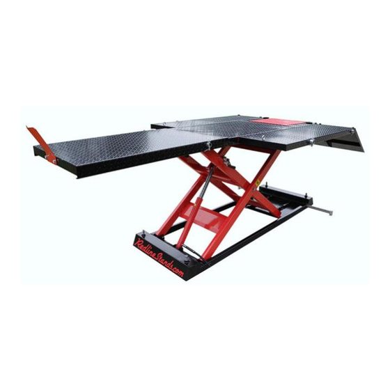
- Page 1 Redline TR1500 Trike Motorcycle Lift Table Assembly & Operation Manual...
- Page 2 Step 1 Use the provided bolts shown to secure the front wheel stop to the front of either the lift itself, or to the front of the front extension panel if you intend to use the front extension panel. We do not recommend using the front extension unless you actually have an unusually long motorcycle and require this panel.
- Page 3 Step 2 Assuming you wish to install the front extension, it slides over the front of the table as shown.
- Page 4 Be sure to line up the large holes on the sides of the front extension panel with the same holes found in the lift table. Next, you’ll install the front extension support pole. The TR1500 comes with 4 poles total as shown below. The 2 longest poles support the side extensions (installed later).
- Page 5 You’ll insert the shortest pole through the front extension panel and also through the lift table at the same time, resulting in the shortest pole slightly exiting the front extension panel on both sides. Once done, you’ll insert the provided clevis pin and cotter pin on each side of the front extension support pole...
- Page 6 Step 3 Next, you’ll insert the middle length pole into the base of the machine. This is an anti-tip stabilizer bar.
- Page 7 You’ll then use the pictured hardware to install the tip-over feet into the ends of the tip-over bar.
- Page 8 Step 4 In step 4, you’ll insert the 2 longest support poles into the 2 most rearward holes in the lift’s tabletop, and then slide the side extensions over those protruding bars. Again, using the supplied hardware you’ll insert all 4 clevis and cotter pins, effectively pinning the side extensions into place so that they cannot possibly slide off without intentionally doing so.
- Page 9 Step 5 Next, you’ll attach the 3 piece ramp assembly to the table top as shown using the hooks of the ramps to drop into the holes in the table top, as well as the holes in the side extensions Hardware is supplied to bolt all three ramps together, but we do not recommend doing so as it makes it especially difficult to remove and replace the ramps when all three are connected.
- Page 10 If you purchased the optional wheel vise with your trike lift, both your table and your front extension panel come pre-drilled with the necessary mounting holes to install the Redline wheel vise to this table as shown. Be sure to use ratchet straps to secure your bike to the lift as the wheel vise alone is not sufficient to hold the...
- Page 11 Step 7 Install the eye bolts into the front of the side extensions using the washer and nut as shown below. These eye bolts allow you to attach ratchet straps to the table top and thus, firmly secure the load to the lift.
- Page 12 Step 8 Now it’s time to connect your pump to the table. Simply remove the red cap as shown in the photo below and thread the lift’s hydraulic hose into the pump, being sure not to over tighten with pliers. Firm hand-tightening is fine.
- Page 13 The standard pump for the TR1500 will come with an air hose and hand operated air valve. If you wish to operate your table via compressed air, you’ll now connect your air hose to the valve shown below. The air motor portion of this pump requires at least 100 psi to operate.
- Page 14 Step 9 If you purchased the optional electric upgrade for the TR1500, you’ll connect your hydraulic hose as shown, being sure not to over tighten with pliers. Firm hand-tightening is fine. Similar to the standard air-over-hydraulic pump, the release pressure of the electric pump can be raised by locating and watching this different video on YouTube.
- Page 15 The electric pump already comes with a substantial amount of electrical cord. We do not recommend using a long, thin extension cord to operate the electric pump as you may experience significant “amp loss” and harm the motor. If you’re going to use an extension cord, the shorter and thicker the size of the cord, the better.
- Page 16 Step 10 It is recommended the customer always lower the lift and rest the weight of the load onto the safety locks when in use and not rely on the hydraulic pump to hold pressure in order to support the weight of the load. To operate the safety lock, simply move this lever shown below to the left or right, respectively, to engage and disengage the safety locking bar, also pictured below toward the bottom.
- Page 17 Step 11 The drop out panel is easily installed and removed with no tools or hardware. Notice in this picture below that the side extension support pole runs through the drop out panel, effectively rendering the drop out panel ineffective for rear wheel removal. For this reason, rear tire changes are typically not possible if the side extensions are installed, so be sure to leave them off the table if this is your intent.
- Page 18 The casters are only strong enough to support the table itself, and nothing more. Your Redline TR1500 is now ready for use. If you have technical questions about your lift, you can email us at Tech@RedLineStands.com...
Need help?
Do you have a question about the TR1500 and is the answer not in the manual?
Questions and answers
How much hydraulic oil does the air over hydraulic pump hold?
The Redline TR1500 air-over-hydraulic pump requires approximately 1 gallon of #32 hydraulic oil.
This answer is automatically generated