Table of Contents
Advertisement
Quick Links
Unpacking
Thank you for buying the MSI
X370 GAMING M7 ACK
motherboard. Check to make
®
sure your motherboard box contains the following items. If something is missing,
contact your dealer as soon as possible.
Motherboard User
Drivers & Utilities
Guide
Disc
Motherboard
I/O Shield
SLI Bridge
Connector
SATA Cable Labels
1 to 2 LED Extension Y
Cable 80cm x1
SATA Cable x4
Screw
Antenna x2
USB Cable
Wi-Fi/Bluetooth PCIe Card
1
Unpacking
Advertisement
Table of Contents

Related Manuals for MSI X370 GAMING M7 ACK


Summary of Contents for MSI X370 GAMING M7 ACK
-
Page 1: Unpacking
Unpacking Thank you for buying the MSI X370 GAMING M7 ACK motherboard. Check to make ® sure your motherboard box contains the following items. If something is missing, contact your dealer as soon as possible. Motherboard User Drivers & Utilities... -
Page 2: Safety Information
Safety Information The components included in this package are prone to damage from electrostatic discharge (ESD). Please adhere to the following instructions to ensure successful computer assembly. Ensure that all components are securely connected. Loose connections may cause the computer to not recognize a component or fail to start. Hold the motherboard by the edges to avoid touching sensitive components. -
Page 3: Quick Start
Quick Start Preparing Tools and Components AM4 CPU ® Thermal Paste CPU Fan DDR4 Memory Power Supply Unit Chassis SATA Hard Disk Drive Graphics Card SATA DVD Drive A Package of Screws Phillips Screwdriver Quick Start... -
Page 4: Installing A Processor
Installing a Processor https://youtu.be/Xv89nhFk1vc Quick Start... -
Page 5: Installing Ddr4 Memory
Installing DDR4 memory http://youtu.be/T03aDrJPyQs DIMMB2 DIMMB2 DIMMB1 DIMMA2 DIMMA2 DIMMA2 DIMMA1 Quick Start... -
Page 6: Connecting The Front Panel Header
Connecting the Front Panel Header http://youtu.be/DPELIdVNZUI HDD LED + Power LED + HDD LED - Power LED - Reset Switch Power Switch Reset Switch Power Switch JFP1 Reserved No Pin JFP1 HDD LED - HDD LED HDD LED + POWER LED - POWER LED POWER LED + Quick Start... -
Page 7: Installing The Motherboard
Installing the Motherboard Quick Start... -
Page 8: Installing Sata Drives
Installing SATA Drives http://youtu.be/RZsMpqxythc Quick Start... -
Page 9: Installing A Graphics Card
Installing a Graphics Card http://youtu.be/mG0GZpr9w_A Quick Start... -
Page 10: Connecting Peripheral Devices
Connecting Peripheral Devices Quick Start... -
Page 11: Connecting The Power Connectors
Connecting the Power Connectors http://youtu.be/gkDYyR_83I4 ATX_PWR1 CPU_PWR1 Quick Start... -
Page 12: Power On
Power On Quick Start... -
Page 13: Table Of Contents
Contents Unpacking ......................1 Safety Information ....................2 Quick Start ......................3 Preparing Tools and Components ................3 Installing a Processor ..................... 4 Installing DDR4 memory ..................5 Connecting the Front Panel Header ............... 6 Installing the Motherboard ..................7 Installing SATA Drives..................... - Page 14 JBAT1: Clear CMOS (Reset BIOS) Jumper ............43 FLASHB1: BIOS FLASHBACK+ Button ..............43 JLED1: RGB LED connector ................. 44 LED light effect demonstration components ............44 Onboard LEDs ...................... 45 DIMM LEDs ......................45 XMP LED ....................... 45 GPU LED ....................... 45 PCIe x16 slot LEDs....................
- Page 15 GAMING APP ......................80 RAMDISK....................... 85 X-BOOST ....................... 86 MSI SMART TOOL ....................88 Killer Control Center .................... 90 DRAGON EYE ......................91 Nahimic 2 ......................92 XSplit Gamecaster V2 ................... 96 SteelSeries Engine 3 ..................100 CPU-Z........................102 RAID Configuration .................... 103 Using AMD RAID Controller BIOS Configuration Utility ........
-
Page 16: Specifications
Supports ECC UDIMM memory (non-ECC mode) * 7th Gen A-series/ Athlon ™ processors support a maximum of 2400 MHz. Please refer www.msi.com for more information on compatible memory 2x PCIe 3.0 x16 slots (PCIE_2, PCIE_4) RYZEN series processors support x16/x0, x8/x8 mode ƒ... - Page 17 Continued from previous page X370 Chipset ® 6x SATA 6Gb/s ports* 2x M.2 ports (Key M) M2_1 slot supports PCIe 3.0 x4 (RYZEN series processor) ƒ or PCIe 3.0 x2 (7th Gen A-series/ Athlon™ processors) and SATA 6Gb/s 2242/ 2260 /2280 storage devices M2_2 slot supports PCIe 2.0 x4 and SATA 6Gb/s 2242/ ƒ...
- Page 18 Continued from previous page 1x PS/2 keyboard/ mouse combo port 1x Clear CMOS button 3x USB 2.0 Type-A ports 1x LAN (RJ45) port Back Panel 6x USB 3.1 Gen1 Type-A ports Connectors 1x USB 3.1 Gen2 Type-A port 1x USB 3.1 Gen2 Type-C port 5x OFC audio jacks 1x Optical S/PDIF OUT connector 1x 24-pin ATX 12V power connector...
- Page 19 ACPI 5.0, PnP 1.0a, SM BIOS 2.8 Multi-language Drivers COMMAND CENTER LIVE UPDATE 6 SUPER CHARGER GAMING APP RAMDISK X-BOOST MSI SMART TOOL Nahimic Audio Software XSplit Gamecaster V2 Norton Internet Security Solution ™ Google Chrome ,Google Toolbar, Google Drive ™...
- Page 20 Continued from previous page Audio Boost 4 Nahimic 2 Turbo U.2 Turbo M.2 Pump Fan Smart Fan Control Mystic Light Extension Mystic light SYNC EZ DEBUG LED DDR4 Steel Armor M.2 SHIELD FROZR PCI-E Steel Armor U.2 Steel Armor Golden Plated USB with type A+C VR Cover Multi GPU –...
-
Page 21: Block Diagram
Block Diagram 2 Channel DDR4 Memory 1 x M.2 Switch 1 x U.2 PCI Express Bus PCIex4 4 x USB 3.1 Gen1 Realtek ALC1220 Audio Jacks NV6795 Super I/O P/S2 Mouse / Keyboard PCIe x4 slot Switch PCIe x1 slot 1 x M.2 PCIe x1 slot Switch... -
Page 22: Rear I/O Panel
Rear I/O Panel USB 2.0/ Audio Ports BIOS FLASHBACK+ USB 3.1 Gen2 PS/2 USB 3.1 Gen1 USB 3.1 Gen1 USB 3.1 Gen1 Optical S/PDIF-Out USB 2.0 Clear CMOS USB 3.1 Gen2 Type-C Clear CMOS button - Power off your computer. Press and hold the Clear CMOS button for about 5-10 seconds to reset BIOS to default values. -
Page 23: Realtek Hd Audio Manager
Realtek HD Audio Manager After installing the Realtek HD Audio driver, the Realtek HD Audio Manager icon will appear in the system tray. Double click on the icon to launch. Device Selection Advanced Settings Jack Status Application Enhancement Main Volume Connector Strings Profiles... - Page 24 Audio jacks to headphone and microphone diagram Audio jacks to stereo speakers diagram AUDIO INPUT Audio jacks to 7.1-channel speakers diagram AUDIO INPUT Rear Front Side Center/ Subwoofer Rear I/O Panel...
-
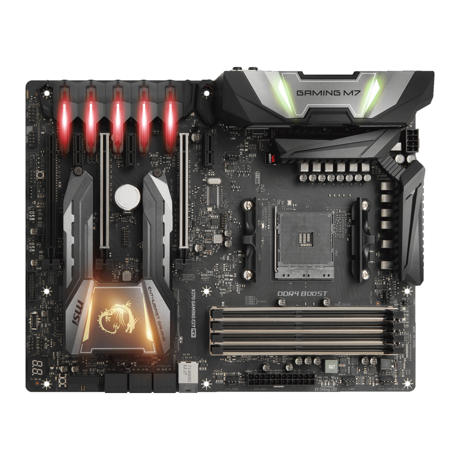
Page 25: Overview Of Components
Overview of Components DIMMA1 DIMMB1 SYS_FAN1 DIMMA2 DIMMB2 CPU_FAN1 CPU_PWR1 CPU Socket PUMP_FAN1 SYS_FAN4 ATX_PWR1 SYS_FAN3 PCI_E1 U2_1 PCI_E2 M2_1 SATA▼5▲6 JCI1 JTPM1 SATA▼1▲2 PCI_E3 JBAT1 SATA▼3▲4 PCI_E4 JUSB4 PCI_E5 M2_2 FLASHB1 PCI_E6 JFP2 JAUD1 JCOM1 JFP1 JUSB1 JUSB5 JLED1 SYS_FAN2 JUSB2 DEMOLED1... - Page 26 Component Contents Port Name Port Type Page CPU_FAN1, PUMP_FAN1, Fan Connectors SYS_FAN1~4 CPU_PWR1, ATX_PWR1 Power Connectors CPU Socket AM4 CPU Socket DIMMA1, DIMMA2, DIMM Slots DIMMB1, DIMMB2 FLASHB1 BIOS FLASHBACK+ Button JAUD1 Front Audio Connector JBAT1 Clear CMOS (Reset BIOS) Jumper JCI1 Chassis Intrusion Connector JFP1, JFP2...
-
Page 27: Cpu Socket
This motherboard is designed to support overclocking. Before attempting to overclock, please make sure that all other system components can tolerate overclocking. Any attempt to operate beyond product specifications is not recommended. MSI does not guarantee the damages or risks caused by ®... -
Page 28: Dimm Slots
Due to AM4 CPU/memory controller official specification limitation, the frequency of memory modules may operate lower than the marked value under the default state. Please refer www.msi.com for more information on compatible memory. Overview of Components... -
Page 29: Pci_E1~6: Pcie Expansion Slots
Important If you install a large and heavy graphics card, you need to use a tool such as MSI Gaming Series Graphics Card Bolster to support its weight to prevent deformation of the slot. For a single PCIe x16 expansion... - Page 30 PCIe bandwidth table For RYZEN series processors Slot Single 2-Way 3-Way PCI_E1 Gen 2.0 x 1 Gen 2.0 x 1 Gen 2.0 x 1 PCI_E2 Gen 3.0 x 16* Gen 3.0 x 8* Gen 3.0 x 8* PCI_E3 Gen 2.0 x 1 Gen 2.0 x 1 Gen 2.0 x 1 ─...
- Page 31 Installing SLI graphics cards For power supply recommendations for SLI configurations, please refer to the user guide of your graphics card to make sure you meet all the system requirements. To install SLI graphics cards: Turn off your computer and disconnect the power cord, install two graphics cards into the PCI_E2 and PCI_E4 slots.
-
Page 32: Installing The Wi-Fi/Bluetooth Pcie Card
Installing the Wi-Fi/Bluetooth PCIe card Install the Wi-Fi/Bluetooth PCIe card in a PCIe x1 slot. Connect one end of the USB cable to the USB connector on the card. Connect the other end of the USB cable to the USB 2.0 connector on the motherboard. -
Page 33: M2_1~2: M.2 Slots (Key M)
M2_1~2: M.2 Slots (Key M) Using M.2 SHIELD FROZR This motherboard has M.2 SHIELD FROZR on the M.2 slots for heat dissipation from the M.2 modules. Before installing the M.2 module for the first time, you need to remove two screws, lift the M.2 SHIELD FROZR and remove the protective films from the thermal pads. -
Page 34: U2_1: U.2 Connector
U2_1: U.2 Connector This connector is a U.2 interface port, which can connect to PCIe 3.0 x4 (RYZEN series processors) or PCIe 3.0 x2 (7th Gen A-series/ Athlon™ processors) NVMe storage device. Video Demonstration Watch the video to learn how to Install U.2 SSD. -
Page 35: Sata1~6: Sata 6Gb/S Connectors
SATA1~6: SATA 6Gb/s Connectors These connectors are SATA 6Gb/s interface ports. Each connector can connect to one SATA device. SATA6 SATA5 SATA2 SATA1 SATA4 SATA3 Important Please do not fold the SATA cable at a 90-degree angle. Data loss may result during transmission otherwise. - Page 36 M.2 slots with examples of various combination possibilities 1xM.2 PCIe SSD + 1xM.2 SATA SSD 2xM.2 PCIe SSDs + 6xSATA HDDs + 5xSATA HDDs + 1xU.2 SSD U2_1 PCIe SATA PCIe PCIe 2xM.2 SATA SSDs + 4xSATA HDDs 1xM.2 PCIe SSD + 1xM.2 SATA SSD + 1xU.2 SSD + 1xPCI_E6 device + 5xSATA HDDs + 1xPCI_E6 device U2_1...
-
Page 37: Cpu_Pwr1, Atx_Pwr1: Power Connectors
CPU_PWR1, ATX_PWR1: Power Connectors These connectors allow you to connect an ATX power supply. CPU_PWR1 Ground +12V Ground +12V Ground +12V Ground +12V +3.3V +3.3V +3.3V -12V Ground Ground PS-ON# Ground Ground Ground ATX_PWR1 Ground Ground PWR OK 5VSB +12V +12V +3.3V Ground... -
Page 38: Jusb1~2: Usb 2.0 Connectors
JUSB1~2: USB 2.0 Connectors These connectors allow you to connect USB 2.0 ports on the front panel. USB0- USB1- USB0+ USB1+ Ground Ground No Pin Important Note that the VCC and Ground pins must be connected correctly to avoid possible damage. -
Page 39: Jusb3~4: Usb 3.1 Gen1 Connectors
However, when you boot the computer into Windows ® you will need to install the MSI SUPER CHARGER application to turn ON/OFF the ®... -
Page 40: Cpu_Fan1, Pump_Fan1, Sys_Fan1~4: Fan Connectors
CPU_FAN1, PUMP_FAN1, SYS_FAN1~4: Fan Connectors Fan connectors can be classified as PWM (Pulse Width Modulation) Mode or DC Mode. PWM Mode fan connectors provide constant 12V output and adjust fan speed with speed control signal. DC Mode fan connectors control fan speed by changing voltage. -
Page 41: Jaud1: Front Audio Connector
JAUD1: Front Audio Connector This connector allows you to connect audio jacks on the front panel. MIC L Ground MIC R Head Phone R MIC Detection SENSE_SEND No Pin Head Phone L Head Phone Detection JCI1: Chassis Intrusion Connector This connector allows you to connect the chassis intrusion switch cable. Normal Trigger the chassis intrusion event... -
Page 42: Jfp1, Jfp2: Front Panel Connectors
JFP1, JFP2: Front Panel Connectors These connectors connect to the switches and LEDs on the front panel. JFP1 HDD LED + Power LED + HDD LED - Power LED - Reset Switch Power Switch Reset Switch Power Switch Reserved No Pin Speaker - Buzzer + JFP2... -
Page 43: Jbat1: Clear Cmos (Reset Bios) Jumper
JBAT1: Clear CMOS (Reset BIOS) Jumper There is CMOS memory onboard that is external powered from a battery located on the motherboard to save system configuration data. If you want to clear the system configuration, set the jumpers to clear the CMOS memory. Keep Data Clear CMOS/ Reset BIOS... -
Page 44: Jled1: Rgb Led Connector
JLED1: RGB LED connector These connectors allow you to connect the 5050 RGB LED strips. +12V 5050 LED strip Extension cable JLED1 Video Demonstration Watch the video to learn how to install 5050 RGB LED strips to RGB LED connector. https://youtu.be/CqNHyADzd2Q Important This connector supports 5050 multi-color LED strips with the maximum power... -
Page 45: Onboard Leds
Onboard LEDs DIMM LEDs These LEDs indicate the memory modules are installed. XMP LED This LED indicates the A-XMP (AMD-Extreme Memory Profile) mode is enabled. DIMM LEDs XMP LED GPU LED This LED indicates the CPU’ s iGPU is not detected and you need to install a graphics card. -
Page 46: Fan Leds
Fan LEDs These LEDs indicate the fan control mode. PUMP_FAN1 LED LED Color Fan control mode CPU_FAN1 LED PWM mode Green DC mode EZ Debug LED These LEDs indicate the debug status of the motherboard. CPU - indicates CPU is not detected or fail. DRAM - indicates DRAM is not detected or fail. -
Page 47: Debug Code Led
Debug Code LED The Debug Code LED displays progress and error codes during and after POST. Refer to the Debug Code LED table for details. Debug Code LED Hexadecimal Character Table Hexadecimal Debug Code 0 1 2 3 4 5 6 7 8 9 A B C D E F LED display Boot Phases Security (SEC) –... - Page 48 Pre-memory PCH initialization (PCH System Agent DXE initialization (System 1A - 1C 6B - 6F module specific) Agent module specific) Memory initialization. Serial Presence PCH DXE initialization is started Detect (SPD) data reading PCH DXE SMM initialization is started Memory initialization. Memory presence PCH devices initialization detection PCH DXE Initialization (PCH module...
-
Page 49: Acpi States Codes
Runtime Set Virtual Address MAP Begin S3 OS Wake Error Runtime Set Virtual Address MAP End EC - EF Reserved for future AMI error codes Legacy Option ROM Initialization Recovery Progress Codes System Reset Recovery condition triggered by firmware USB hot plug (Auto recovery) PCI bus hot plug Recovery condition triggered by user... -
Page 50: Bios Setup
BIOS Setup The default settings offer the optimal performance for system stability in normal conditions. You should always keep the default settings to avoid possible system damage or failure booting unless you are familiar with BIOS. Important BIOS items are continuously update for better system performance. Therefore, the description may be slightly different from the latest BIOS and should be for reference only. -
Page 51: Resetting Bios
Updating BIOS Updating BIOS with M-FLASH Before updating: Please download the latest BIOS file that matches your motherboard model from MSI website. And then save the BIOS file into the USB flash drive. Updating BIOS: Press Del key to enter the BIOS Setup during POST. - Page 52 Before updating: Please download the latest BIOS file that matches your motherboard model from MSI ® website and rename the BIOS file to MSI.ROM. And then, save the MSI.ROM file to the root of USB flash drive. Using FLASHBACK+ button: Connect power supply to ATX_PWR1 and CPU_PWR1.
-
Page 53: Ez Mode
EZ Mode At EZ mode, it provides the basic system information and allows you to configure the basic setting. To configure the advanced BIOS settings, please enter the Advanced Mode by pressing the Setup Mode switch or F7 function key. Setup Mode switch Screenshot Search... - Page 54 Important During windows setup, the RAID driver may be required and you can find the RAID driver in MSI Driver Disc. You can use MSI SMART TOOL to build the Windows 7/ 10 installation drive that ® includes RAID driver.
-
Page 55: Advanced Mode
Advanced Mode Press Setup Mode switch or F7 function key can switch between EZ Mode and Advanced Mode in BIOS setup. Setup Mode switch Screenshot Search Language System information GAME BOOST switch Boot device priority bar BIOS menu BIOS menu selection selection Menu display... -
Page 56: Settings
SETTINGS System Status System Date Sets the system date. Use tab key to switch between date elements. The format is <day> <month> <date> <year>. <day> Day of the week, from Sun to Sat, determined by BIOS. Read-only. <month> The month from Jan. through Dec. <date>... - Page 57 fPower LED [Blinking] Sets shining behaviors of the onboard Power LED. [Dual Color] The power LED turns to another color to indicate the S3 state. [Blinking] The power LED blinks to indicate the S3 state. Integrated Peripherals Sets integrated peripherals’ parameters, such as LAN, HDD, USB and audio. Press Enter to enter the sub-menu.
- Page 58 fHD Audio Controller [Enabled] Enables or disables the onboard High Definition Audio controller. USB Configuration Sets the onboard USB controller and device function. Press Enter to enter the sub- menu. fXHCI Hand-off [Enabled] Enables or disables XHCI hand-off support. [Enabled] Enables this item when installing the operating system which does not support USB 3.0.
- Page 59 [Last State] Restores the system to the previous state (power on/ power off) before AC power loss. fSystem Power Fault Protection [Disabled] Enables or disables the system to boot up when detecting abnormal voltage input. [Enabled] Protect the system from unexpected power operating and remain the shut down status.
- Page 60 fWake Up Event By [BIOS] Selects the wake up event by BIOS or operating system. [BIOS] Activates the following items, set wake up events of these items. [OS] The wake up events will be defined by OS. fResume By RTC Alarm [Disabled] Disables or enables the system wake up by RTC Alarm.
-
Page 61: Boot
Secure Erase+ Enables or disables Secure Erase+ function. Secure Erase+ is the best way to effectively wipe all data from a SSD. Please note that data of SSD will be erased after enabling Secure Erase+. Boot Sets the sequence of system boot devices. Full Screen Logo Display [Enabled] Enables or disables to show the full screen logo while system POST. - Page 62 Password Check [Setup] Selects a condition that will request the password. [Setup] A password will be requested for entering the BIOS Setup. [Boot] A password will be requested for booting the system. Password Clear [Enabled] Enables or disables the clear CMOS behavior to clear a set password. [Enabled] The password will be erased after clear CMOS.
-
Page 63: Save & Exit
fChassis Intrusion [Disabled] Enables or disables recording messages while the chassis is opened. This function is ready for the chassis equips a chassis intrusion switch. [Enabled] Once the chassis is opened, the system will record and issue a warning message. [Reset] Clear the warning message. - Page 64 Important Overclocking your PC manually is only recommended for advanced users. Overclocking is not guaranteed, and if done improperly, it could void your warranty or severely damage your hardware. If you are unfamiliar with overclocking, we advise you to use GAME BOOST function for easy overclocking.
- Page 65 Memory Try It ! [Disabled] It can improve memory compatibility or performance by choosing optimized memory preset. Memory Retry Count [5] Sets counts for memory OC retrying. When memory OC has failed, setting this item as [5] will allow system to reboot 5 times with the same overclocked configuration. If overclocking has failed every time, the system will restore the defaults.
- Page 66 fCPU Power Duty Control [Thermal Balance] Sets the current of every VRM phase and the thermal conditions of every phase component. [Thermal Balance] Maintains the VRM thermal balance. [Current Balance] Maintains the current VRM balance. fCPU NB Loadline Calibration Control [Auto] The CPU-NB voltage will decrease proportionally according to CPU-NB loading.
- Page 67 CPU Memory Changed Detect [Enabled]* Enables or disables the system to issue a warning message during boot when the CPU or memory has been replaced. [Enabled] The system will issue a warning message during boot and then you have to load the default settings for new devices. [Disabled] Disables this function and keeps the current BIOS settings.
- Page 68 Important If you do not have any EMI problem, leave the setting at [Disabled] for optimal system stability and performance. But if you are plagued by EMI, select the value of Spread Spectrum for EMI reduction. The greater the Spread Spectrum value is, the greater the EMI is reduced, and the system will become less stable.
-
Page 69: M-Flash
M-FLASH provides the way to update BIOS with a USB flash drive. Please down-load the latest BIOS file that matches your motherboard model from MSI website, save the BIOS file into your USB flash drive. And then follow the steps below to update BIOS. -
Page 70: Oc Profile
OC PROFILE Overclocking Profile 1/ 2/ 3/ 4/ 5/ 6 Overclocking Profile 1/ 2/ 3/ 4/ 5/ 6 management. Press <Enter> to enter the sub- menu. fSet Name for Overclocking Profile 1/ 2/ 3/ 4/ 5/ 6 Name the current overclocking profile. fSave Overclocking Profile 1/ 2/ 3/ 4/ 5/ 6 Save the current overclocking profile. -
Page 71: Hardware Monitor
HARDWARE MONITOR Temperature & Speed Fan Manage Setting Buttons Voltage display Temperature & Speed Shows the current CPU temperature, system temperature and fans' speeds. Fan Manage PWM - allows you to select the PWM mode for fan operation. ƒ DC - allows you to select the DC mode for fan operation. ƒ... -
Page 72: A-Xmp Operation
A-XMP Operation System Requirements X370, B350 and A320 series motherboard ® Supported AMD RYZEN series processor ® Memory module supports XMP How to enable A-XMP Power on and press Delete key to enter BIOS Setup menu. Here are two methods below to enable A-XMP. -
Page 73: Software Description
7/ 10 disc into your optical drive. ® Note: Due to chipset limitation, during the Windows 7 installation process, USB optical drives or USB flash drives are not supported. You can use MSI Smart Tool to install Windows ® Press the Restart button on the computer case. -
Page 74: Live Update 6
LIVE UPDATE 6 LIVE UPDATE 6 is an application for the MSI system to scan and download the latest ® drivers, BIOS and utilities. With LIVE UPDATE 6, you don’ t need to search the drivers on websites, and don’ t need to know the models of motherboard and graphics cards. - Page 75 Select the Live Update tab. Choose Automatic scan, system will automatically scan all the items and search for the latest update files. Or you can choose Manual scan and select the items you wish to scan. Click the Scan button at the bottom. It may take several moments to complete the process.
-
Page 76: Command Center
COMMAND CENTER COMMAND CENTER is an user-friendly software and exclusively developed by MSI, helping users to adjust system settings and monitor status under OS. With the help of COMMAND CENTER, making it possible to achieve easier and efficient monitoring process and adjustments than that under BIOS. In addition, the COMMAND CENTER can be a server for mobile remote control application. - Page 77 CPU Fan CPU Fan control panel provides Smart mode and Manual Mode. You can switch the control mode by clicking the Smart Mode and Manual Mode buttons on the top of the CPU Fan control panel. Manual Mode - allows you to manually control the CPU fan speed by percentage.
- Page 78 GAME BOOST GAME BOOST provides a specified CPU frequency for overclocking the CPU. Option Buttons - Advanced When click the Advanced button, The Voltage, Fan, DRAM and Sensor icons will appear. Voltage - allows you to adjust advanced voltage values of CPU and chipset. Fan - allows you to control the system fans speed.
- Page 79 Find the IP address on the SoftAP Management Setting area, and enter the IP address on your MSI COMMAND CENTER APP to link your system. ® Press Refresh on the MSI COMMAND CENTER APP to verify that monitoring and ® OC functions are working properly.
-
Page 80: Gaming App
Connect your android device and motherboard to the same local area network. Run MSI GAMING APP APP on your android device. ® Press the Remote Control Setting icon on the MSI GAMING APP APP to find the ® paired device Name you set in the Remote Control Setting panel. - Page 81 LED function allows you to control LED lights on your motherboard. ON/OFF LED Area Selection LED ON/OFF - allows you to turn ON/ OFF the LED function. LED Area Selection - separately controls each segment of LEDs on your motherboard and graphics cards. LED effects - switches LEDs on or off.
- Page 82 Eye Rest Eye Rest allows you to optimize the display on your monitor. EyeRest - reduces blue-light of your LED backlit screen, in order to protect your eyes. Gaming - automatically increases contrast ratio of your screen. Movie - automatically increases dynamic contrast ratio of your screen. Customize - allows you to adjust gamma, contrast and color balance for your screen.
- Page 83 Login Keys - provides hotkey login function. ƒ MSI Smart Keys - allows you to define hotkeys for MSI Smart Keys. ƒ Hotkey Manager - allows you to create, edit and delete hotkeys. Current Hotkeys - shows all existing hotkeys.
- Page 84 Mouse Master Mouse Master provides mouse macro function. You can also use it to change DPI of your mouse. DPI Setting Delay Time Default Button Macro Hot Key DPI Hot Key Mouse Action Action List Test Area Edit Buttons Clear Button Load Button Save Button Delay Time - allows you to apply a delay time in mouse macro.
-
Page 85: Ramdisk
RAMDISK RAMDISK creates a virtual RAM drive using the available memory in your computer, the performance of the RAMDISK is faster than an SSD and hard drive. RAMDISK allows you to store any temporary information on it. Furthermore, using the RAMDISK will extend your SSD’... -
Page 86: X-Boost
X-BOOST The MSI X-BOOST allows you to select the system performance mode to meet your current system environment or supports faster storage access speed. Most of the external storage and memory cards can also benefit this feature. Easy In Easy page, you can select one system performance mode to meet the current system environment. - Page 87 STORAGE BOOST - supports faster access speed of storage device. Important Please note that you can only select one mode at a time from Easy or Advance page as MSI X-BOOST function. The improved transfer rate/ access speed will vary with the USB/ storage device. Software Description...
-
Page 88: Msi Smart Tool
USB flash drive with USB 3.0 drivers, and it can also create a SUPER RAID. Main menu After installing and activating MSI SMART TOOL, it will display a main menu for you to choose Win7 Smart Tool or SUPER RAID. Note that the SUPER RAID is only available when your system equipped with at least 3 hard-disk drives (1 system disk and 2 data disks). - Page 89 SUPER RAID This utility allows you to create a SUPER RAID in Windows system. To create a SUPER RAID: Use checkboxs to select the disks you want included in your RAID. Choose Speed Up or Backup for RAID type. y Speed Up = RAID0 y Backup = RAID1 Click Start.
-
Page 90: Killer Control Center
Killer Control Center The Killer Control Center software can be installed with the Killer LAN driver. Once installed, the Killer Control Center icon would appear in system tray (bottom right of the screen). Right click on the icon to open application window. In case no icon appears in system tray, you may activate Killer Control Center manually by double clicking the Killer Control Center icon on the desktop. -
Page 91: Dragon Eye
DRAGON EYE DRAGON EYE is an application allows you to watch a game guide, tutorial, live match or tournament stream while playing a game. In the game, you can use hotkeys to control / adjust the window of video. Size Settings Position Settings On / Off Switch Help... -
Page 92: Nahimic 2
HD Audio Recorder2 and Sound Tracker. Installation and Update Nahimic 2 is included in the audio driver. If you need to install it or update it, please use the Driver Disc with your motherboard or download the driver from MSI’ s official website. Audio Tab From this tab, you can access all of Nahimic 2’... - Page 93 Smart Loudness - maintains a constant volume for all elements of the audio ƒ experience to making them all sound softer, balanced or louder. Voice Clarity - boosts the speech in movies, video games and incoming ƒ communication from +0 through +12 dB (0 to 100%). Reset Button - restores the current profile to its default values.
- Page 94 Device properties - allows you to boost the volume and modify the left/ right ƒ balance of microphone. Clicks on this button and a device properties panel will show. Microphone Loopback - turns the microphone loopback On/Off. In order to avoid any feedback (Larsen effect).
- Page 95 Control Page - by clicking the arrow button, you can access the control page. Audio Launchpad ON/OFF - switches the Audio Launchpad on or off. ƒ HD Audio Recorder 2 - The HD Audio Recorder 2 is, by default, automatically ƒ...
-
Page 96: Xsplit Gamecaster V2
Login button. Important When starting XSplit Gamecaster V2 on select MSI gaming laptops, all-in ones or on ® machines that contain select MSI motherboards or graphics cards, you will receive ®... - Page 97 Learning stream and record Refer to the Start page of XSplit Gamecaster V2 to learn how to stream and record your gameplay. Tool Tip When you click the question mark next to a feature name on the panel, a tooltip will show, describing the particular function of that item.
- Page 98 Share Button - If you authorize your Facebook, Twitter, and/or Google+ accounts, you can quickly share your stream URL and status update within the overlay. Annotations - This feature of XSplit Gamecaster V2 allows you to draw directly onto your game play. You can activate annotation mode by clicking on the pencil button in the overlay.
- Page 99 Microphone Settings - In this region, you can select your desired microphone. What is shown in the list depends on what you have connected to your PC. If you don’ t see your desired device in the list, please make sure that it is detected and it is not disabled in your recording devices list in the Windows Sound Menu (Start >...
-
Page 100: Steelseries Engine 3
SteelSeries Engine 3 SteelSeries Engine 3 is a unified platform built to support all of SteelSeries products. It can deploy your saved device settings automatically when switching between your favorite games or applications. After installation the SteelSeries Engine background processes will start and the interface will open automatically. - Page 101 Configuring Your Devices You can custom configurations for SteelSeries devices in their Configuration Windows. The top left displays the name of the configuration you are viewing, the body features widgets for customizing various functions of the device, and at the bottom are Save/ Revert buttons, a Live Preview toggle, and a button to open/close the collapsible Configuration List Panel.
-
Page 102: Cpu-Z
CPU-Z CPU-Z is an utility that gathers information on some of the main devices of your system. CPU Tab - shows processor name, code name, package, specification, instructions sets, core speed and cache levels. Caches Tab - shows extended information related to the cache capabilities. Mainboard Tab - shows motherboard manufacturer, model name, chipset, BIOS version and graphic interface. -
Page 103: Raid Configuration
RAID Configuration Below are the different types of a RAID. RAID 0 breaks the data into blocks which are written to separate hard drives. Spreading the hard drive I/O load across independent channels greatly improves I/O performance. RAID 1 provides data redundancy by mirroring data between the hard drives and provides enhanced read performance. - Page 104 Using the utility to accomplish the procedures Initialize Disk(s) - To initialize a new disk drive for data storage. Create Array - Create arrays at different RAID levels (depending on the license level for the system) Delete Array(s) - Delete an array. Swap Two Arrays - Change the array order, especially for the AMD-RAID bootable array.
-
Page 105: Initialize Disks
Initialize Disks New disks and legacy disks must be initialized before they can be used to create an AMD-RAID array. Initialization writes AMD-RAID configuration information (metadata) to a disk. Important If a disk is part of an AMD-RAID array, the disk cannot be selected for initialization. To initialize the disk anyway, delete the AMD-RAID array. -
Page 106: Create Arrays
Create Arrays Arrays can be created after the disks are initialized. Important For redundant arrays, the Create process is not finished until after the operating system and AMD-RAID OS drivers have been installed and the system has booted to the operating system. However, the arrays are immediately available to use for either a bootable array or a data array. -
Page 107: Delete Arrays
Delete Arrays Important Deleting an array permanently destroys all data that is on the array. This action cannot be undone and it is very unlikely the data can be recovered. To delete an array At the Main Menu, use the arrow keys to highlight Delete Array and press Enter. AMD-RAID Array Configuration Deletes one or more arrays that are configured on this controller Arrays... -
Page 108: Swap Arrays
Swap Arrays Use the Swap Two Arrays option to arrange arrays in a different order. Important If more than one array is created, install the operating system to any of them. However, a small amount of boot information is always written to a disk(s) in the first array (Array 1) of the Array section, regardless on which array the operating system is installed. -
Page 109: Manage Spares
Manage Spares This option allows the user to assign or unassign global or dedicated spares. At the Main Menu, use the arrow keys to highlight Manage Host Spare(s) and press Enter to enter submenu. AMD-RAID Array Configuration Assign Global Hot Spare(s) Arrays Disks 1----RAID0, 999GB, Normal(R/W) -
Page 110: Change The Controller Options
Change the Controller Options Controller Options allows the user to configure options for the boot sequence. At the Main Menu, use the arrow keys to highlight Controller Options and press Enter to enter submenu. AMD-RAID Array Configuration Toggles whether BIOS installs INT13 support Arrays Disks 1----RAID0, 999GB, Normal(R/W) -
Page 111: Change The Staggered Spinup Count
Change the Staggered Spinup Count Depending on a system’ s power supply load-rating, you might want to limit the number of disks that are spun-up together when a system is powered on. At the Controller Options submenu, use the arrow keys to highlight Set Staggered Spinup Count and press Enter. -
Page 112: Using Uefi To Create A 2.2Tb Raid
Using UEFI to create a 2.2TB RAID If you plan to create a RAID volume greater than 2.2TB, you can only manually create the RAID array in UEFI mode. The steps are described below. WARNING Create raid array will erase all the data stored on hard drives! Make sure to back up your files! There is no way to reverse the process! Power on and press Delete key to enter BIOS Setup menu. -
Page 113: Installing Raid Driver
When prompted, insert the USB flash drive with AMD RAID Drivers and then click Browse. To make an AMD RAID Drivers USB flash drive. Insert the MSI Driver Disc into ƒ the optical drive. Copy all the contents in \\Chipset\Packages\Drivers\SBDrv\ RAID_AM4 Navigate to the directory containing the saved AMD RAID drivers, then click OK. -
Page 114: Troubleshooting
Troubleshooting Lost BIOS password Before sending the motherboard for RMA repair, try to go over troubleshooting Clear the CMOS, but that will cause guide first to see if your got similar you to lose all customized settings in symptoms as mentioned below. the BIOS. -
Page 115: Regulatory Notices
The point of contact for regulatory matters is MSI, recycling and disposing of their end-of-life products. MSI-NL Eindhoven 5706 5692 ER Son. y Visit the MSI website and locate a nearby distributor B급 기기 (가정용 방송통신기자재) for further recycling information. - Page 116 MSI will comply with the product take entregar a una empresa autorizada para la recogida de back requirements at the end of life of MSI-branded estos residuos.
- Page 117 及醫療用電波輻射性電機設備之干擾 。 saranno obbligati a ritirare ogni prodotto alla fine del suo ciclo di vita. MSI si adeguerà a tale Direttiva Products with radio functionality (EMF) ritirando tutti i prodotti marchiati MSI che sono stati This product incorporates a radio transmitting venduti all’interno dell’Unione Europea alla fine del...
- Page 118 Alternatively, please try the following help resources for further guidance. y Visit the MSI website for technical guide, BIOS updates, driver updates, and other information: http://www.msi.com y Register your product at: http://register.msi.com...
Need help?
Do you have a question about the X370 GAMING M7 ACK and is the answer not in the manual?
Questions and answers