Table of Contents
Advertisement
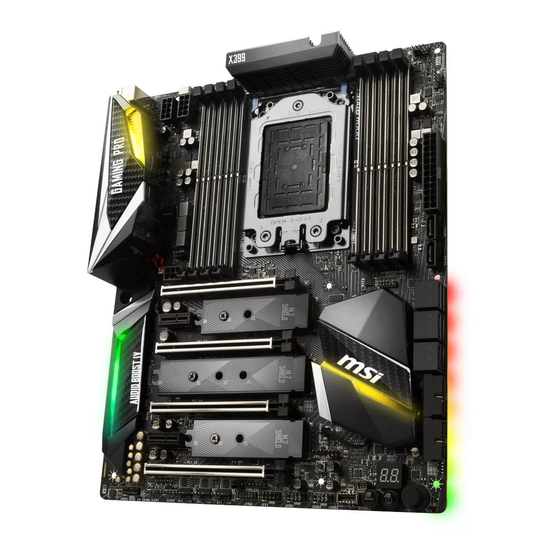
Unpacking
Thank you for buying the MSI
to make sure your motherboard box contains the following items. If something is
missing, contact your dealer as soon as possible.
Motherboard
1 to 2 RGB LED Extension
Y Cable 80cm x1
Exchangeable
Plates Box x1*
Wi-Fi/Bluetooth PCIe Card
* MSI
does not guarantee the risks or damages caused by changing the cover.
®
** These pictures are for reference only and may vary without notice.
X399 GAMING PRO CARBON AC
®
Drivers & Utilities
Disc
SATA Cable x4
Quick Guide
OC Fan Stand
USB Cable
motherboard. Check
Motherboard User
Guide
SATA Cable Labels
Case Badge
Screw
Antenna x2
SLI Bridge
Connector
I/O Shield
3D X-MOUNTING
Screw Pillars
Unpacking
1
Advertisement
Table of Contents

Subscribe to Our Youtube Channel
Related Manuals for MSI X399 GAMING PRO CARBON AC


Summary of Contents for MSI X399 GAMING PRO CARBON AC
-
Page 1: Unpacking
Unpacking Thank you for buying the MSI X399 GAMING PRO CARBON AC motherboard. Check ® to make sure your motherboard box contains the following items. If something is missing, contact your dealer as soon as possible. Drivers & Utilities Motherboard User... -
Page 2: Safety Information
Safety Information y The components included in this package are prone to damage from electrostatic discharge (ESD). Please adhere to the following instructions to ensure successful computer assembly. y Ensure that all components are securely connected. Loose connections may cause the computer to not recognize a component or fail to start. -
Page 3: Quick Start
Quick Start Preparing Tools and Components Ryzen ® Thermal Paste Threadripper CPU CPU Fan DDR4 Memory Power Supply Unit Chassis SATA Hard Disk Drive Graphics Card SATA DVD Drive Phillips Screwdriver Torqkey Screwdriver A Package of Screws Quick Start... -
Page 4: Installing A Processor
Installing a Processor https://youtu.be/yk4EpVUU03E Quick Start... -
Page 5: Installing Ddr4 Memory
Installing DDR4 memory http://youtu.be/T03aDrJPyQs 1 DIMM 2 DIMMs SocketTR4 CPU 4 DIMMs 8 DIMMs Quick Start... -
Page 6: Connecting The Front Panel Header
Connecting the Front Panel Header http://youtu.be/DPELIdVNZUI HDD LED + Power LED + HDD LED - Power LED - Reset Switch Power Switch Reset Switch Power Switch JFP1 Reserved No Pin JFP1 HDD LED - HDD LED HDD LED + POWER LED - POWER LED POWER LED + Quick Start... -
Page 7: Installing The Motherboard
Installing the Motherboard Quick Start... -
Page 8: Installing Sata Drives
Installing SATA Drives http://youtu.be/RZsMpqxythc Quick Start... -
Page 9: Installing A Graphics Card
Installing a Graphics Card http://youtu.be/mG0GZpr9w_A Quick Start... -
Page 10: Connecting Peripheral Devices
Connecting Peripheral Devices Quick Start... -
Page 11: Connecting The Power Connectors
Connecting the Power Connectors http://youtu.be/gkDYyR_83I4 ATX_PWR1 CPU_PWR1 CPU_PWR2 PCIE_PWR1 Quick Start... -
Page 12: Power On
Power On Quick Start... -
Page 13: Table Of Contents
Contents Unpacking ......................1 Safety Information ....................2 Quick Start ......................3 Preparing Tools and Components ................3 Installing a Processor ..................... 4 Installing DDR4 memory ..................5 Connecting the Front Panel Header ............... 6 Installing the Motherboard ..................7 Installing SATA Drives..................... - Page 14 JBAT1: Clear CMOS (Reset BIOS) Jumper ............44 POWER1, RESET1: Power Button, Reset Button ..........44 JRGB1, JRAINBOW1: RGB LED connectors ............45 Onboard LEDs ...................... 46 EZ Debug LED ....................... 46 PCIe x16 slot LEDs....................46 DIMM LEDs ......................46 XMP LED .......................
- Page 15 GAMING APP ......................80 X-BOOST ....................... 85 MYSTICLIGHT ......................87 MSI SMART TOOL ....................89 RAMDISK....................... 91 GAMING LAN MANAGER ..................92 DRAGON EYE ......................94 Nahimic 2 ......................95 SteelSeries Engine 3 .................... 99 CPU-Z........................101 TriDef VR ......................102 TriDef SmartCam ....................
-
Page 16: Specifications
Supports DDR4 3600+(OC)/ 3466(OC)/ 3333(OC)/ 3200(OC)/ Memory 3066(OC)/ 2933(OC)/ 2800(OC)/ 2667(OC)/ 2400/ 2133 MHz* * For the latest information about memory, please visit http://www.msi.com ** Please refer the DIMM Slots section for more details. y 4x PCIe 3.0 x16 slots Expansion Slots y 2x PCIe 2.0 x1 slots... - Page 17 Continued from previous page y ASMedia ASM3142 Chipset ® ƒ 1x USB 3.1 Gen2 (SuperSpeed USB 10Gbps) Type-C port on the back panel ƒ 1x USB 3.1 Gen2 (SuperSpeed USB 10Gbps) Type-A port on the back panel y AMD X399 Chipset ®...
- Page 18 Continued from previous page y 1x 24-pin ATX main power connector y 2x 8-pin ATX 12V power connector y 1x 6-pin ATX 12V power connector* y 8x SATA 6Gb/s connectors y 2x USB 2.0 connectors (supports additional 4 USB 2.0 ports) y 2x USB 3.1 Gen1 connectors (supports additional 4 USB 3.1 Gen1 ports)
- Page 19 MYSTIC LIGHT Software y RAMDISK y GAMING LAN MANAGER y Nahimic Audio y SteelSeriesEngine 3 y WTFast y CPU-Z MSI GAMING y Norton™ Internet Security Solution y Google Chrome™ ,Google Toolbar, Google Drive y TriDef ® y TriDef SmartCam ®...
- Page 20 Continued from previous page ƒ Audio Boost 4 ƒ Nahimic 2 ƒ GAMING LAN with Gaming LAN Manager ƒ Triple Turbo M.2 ƒ Pump Fan ƒ Smart Fan Control ƒ Mystic Light ƒ Mystic Light Extension ƒ Mystic light SYNC ƒ...
-
Page 21: Block Diagram
Block Diagram 2/ 4 Channel DDR4 Memory Processor 3x M.2 PCI Express Bus 8x USB 3.1 Gen1 Realtek ALC1220 DMI 3.0 Audio Jacks PCIe x1 slot PCIe x1 slot PCIE Bus 8x SATA 6Gb/s X399 Intel 8265 WiFi 4x USB 3.1 Gen1 1x USB 3.1 Gen2 Type C 6x USB 2.0 ASMEDIA... -
Page 22: Rear I/O Panel
Rear I/O Panel Audio Ports VR READY ports BIOS FLASHBACK+ port PS/2 Clear CMOS button Optical S/PDIF-Out BIOS FLASHBACK+ USB 2.0 button USB 3.1 Gen2 Type-C USB 3.1 Gen1 USB 3.1 Gen2 Type-A y Clear CMOS button - Power off your computer. Press and hold the Clear CMOS button for about 5-10 seconds to reset BIOS to default values. -
Page 23: Realtek Hd Audio Manager
Realtek HD Audio Manager After installing the Realtek HD Audio driver, the Realtek HD Audio Manager icon will appear in the system tray. Double click on the icon to launch. Device Selection Advanced Settings Jack Status Application Enhancement Connector Main Volume Strings Profiles y Device Selection - allows you to select a audio output source to change the related... - Page 24 Audio jacks to headphone and microphone diagram Audio jacks to stereo speakers diagram AUDIO INPUT Audio jacks to 7.1-channel speakers diagram AUDIO INPUT Rear Front Side Center/ Subwoofer Rear I/O Panel...
-
Page 25: Overview Of Components
Overview of Components CPU_FAN1 CPU Socket CPU_PWR1 CPU_PWR2 PUMP_FAN1 DIMMB2 DIMMC1 DIMMB1 DIMMC2 DIMMA2 DIMMD1 DIMMA1 DIMMD2 ATX_PWR1 SYS_FAN1 SATA1 PCIE_PWR1 JBAT1 SATA2 PCI_E1 M2_1 SATA▼3▲4 PCI_E2 SATA▼5▲6 PCI_E3 SATA▼7▲8 M2_2 JUSB5 PCI_E4 M2_3 JUSB4 PCI_E5 JFP2 PCI_E6 JSLOW JAUD1 JRGB1 JRAINBOW1 POWER1... - Page 26 Component Contents Port Name Port Type Page CPU_FAN1, PUMP_FAN1, Fan Connectors SYS_FAN1~4 CPU_PWR1~2, ATX_PWR1, Power Connectors PCIE_PWR1 CPU Socket SocketTR4 DIMMA1~DIMMD2 DIMM Slots JAUD1 Front Audio Connector JBAT1 Clear CMOS (Reset BIOS) Jumper JCI1 Chassis Intrusion Connector JFP1, JFP2 Front Panel Connectors JRGB1, JRAINBOW1 RGB LED connectors JSLOW1...
-
Page 27: Cpu Socket
CPU Socket Please use the Torx screwdriver come with the AMD CPU and follow the steps below to install the CPU. Video Demonstration Watch the video to learn how to unbox and install AMD Ryzen Threadripper CPU. https://youtu.be/yk4EpVUU03E 1. Loosen load plate screws with the AMD Torx screwdriver in the sequence 3→2→1. The load plate will automatically lift up to the fully open position. - Page 28 3. Remove the protective pin cap, and then close and buckle the frame rail. Protective pin cap 4. Close the load plate, and then turn the load plate screws clockwise a little with the AMD Torx screwdriver in the sequence 1→2→3→1→2→3 until they are snug. AMD Torx screwdriver 5.
- Page 29 Always unplug the power cord from the power outlet before installing or removing the CPU. Please retain the protective caps after installing the processor. MSI will deal with Return Merchandise Authorization (RMA) requests if only the motherboard comes with the protective caps on the CPU socket.
-
Page 30: Oc1: Game Boost Knob
3. Rotate the GAME BOOST knob to 0 and then power on. The configuration parameters will be returned to default values. Important You can also control the GAME BOOST function in BIOS Setup or with MSI COMMAND CENTER software. In order to optimize performance and improve system stability, when you activate the GAME BOOST function, please leave the settings in the BIOS >... -
Page 31: Jslow1: Slow Mode Booting Jumper
The success of overclocking depends on the components of your computer. We do not guarantee the GAME BOOST overclocking range or the damages/ risks caused by overclocking behavior. MSI components are recommended for better compatibility when using GAME BOOST function. JSLOW1: Slow Mode Booting Jumper... -
Page 32: Dimm Slots
DIMM Slots D2D1C2C1 A1A2B1B2 Memory module installation recommendation CPU Socket 1 DIMM 2 DIMMs SocketTR4 CPU 4 DIMMs 8 DIMMs DIMMB2 DIMMD2 DIMMB2 Overview of Components... - Page 33 DIMMC2 DIMMB2 DIMMB2 DIMMC1 DIMMD2 DIMMA2 DIMMB1 DIMMC2 DIMMD1 DIMMA2 DIMMA1 DIMMD2 Important Always insert a memory module in the DIMMB2 slot first. To ensure system stability for Dual/ Triple/ Quad channel mode, memory modules must be of the same type, number and density. Due to chipset resource usage, the available capacity of memory will be a little less than the amount of installed.
-
Page 34: Pci_E1~6: Pcie Expansion Slots
PCI_E1~6: PCIe Expansion Slots PCI_E1: PCIe 3.0 x16 PCI_E2: PCIe 2.0 x1 PCI_E3: PCIe 3.0 x8 PCI_E4: PCIe 3.0 x16 PCI_E5: PCIe 2.0 x1 PCI_E6: PCIe 3.0 x8 Multiple graphics cards installation recommendation PCI_E1* PCI_E1* PCI_E4 PCI_E1* PCI_E1* PCI_E3 PCI_E3 PCI_E4 PCI_E4 PCI_E6... - Page 35 Important If you install a large and heavy graphics card, you need to use a tool such as MSI Gaming Series Graphics Card Bolster to support its weight and to prevent deformation of the slot. For a single PCIe x16 expansion card installation with optimum performance, using the PCI_E1 slot is recommended.
-
Page 36: Installing The Wi-Fi/Bluetooth Pcie Card
Installing the Wi-Fi/Bluetooth PCIe card 1. Install the Wi-Fi/Bluetooth PCIe card in a PCIe x1 slot. 2. Connect one end of the USB cable to the USB connector on the card. 3. Connect the other end of the USB cable to the USB 2.0 connector on the motherboard. -
Page 37: M2_1~3: M.2 Slots (Key M)
M2_1~3: M.2 Slots (Key M) Video Demonstration Watch the video to learn how to use M.2 Shield. https://youtu.be/NwtQBpkUazs Installing M.2 module 1. Remove the screw from the base screw. 5. Put the screw in the notch on the trailing edge of your M.2 2. -
Page 38: Sata1~8: Sata 6Gb/S Connectors
SATA1~8: SATA 6Gb/s Connectors These connectors are SATA 6Gb/s interface ports. Each connector can connect to one SATA device. SATA1 SATA2 SATA4 SATA3 SATA6 SATA5 SATA8 SATA7 Important Please do not fold the SATA cable at a 90-degree angle. Data loss may result during transmission otherwise. -
Page 39: Cpu_Pwr1~2, Atx_Pwr1, Pcie_Pwr1: Power Connectors
CPU_PWR1~2, ATX_PWR1, PCIE_PWR1: Power Connectors These connectors allow you to connect an ATX power supply. CPU_PWR1/ CPU_PWR2 Ground +12V Ground +12V Ground +12V Ground +12V +3.3V +3.3V +3.3V -12V Ground Ground PS-ON# Ground Ground Ground ATX_PWR1 Ground Ground PWR OK 5VSB +12V +12V... -
Page 40: Jusb1~2: Usb 2.0 Connectors
JUSB1~2: USB 2.0 Connectors These connectors allow you to connect USB 2.0 ports on the front panel. USB0- USB1- USB0+ USB1+ Ground Ground No Pin Important Note that the VCC and Ground pins must be connected correctly to avoid possible damage. -
Page 41: Jusb3: Usb 3.1 Gen2 Type-C Connector
However, when you boot the computer into Windows ® you will need to install the MSI SUPER CHARGER application to turn ON/OFF the ®... -
Page 42: Cpu_Fan1, Pump_Fan1, Sys_Fan1~4: Fan Connectors
CPU_FAN1, PUMP_FAN1, SYS_FAN1~4: Fan Connectors Fan connectors can be classified as PWM (Pulse Width Modulation) Mode or DC Mode. PWM Mode fan connectors provide constant 12V output and adjust fan speed with speed control signal. DC Mode fan connectors control fan speed by changing voltage. When you plug a 3-pin (Non-PWM) fan to a fan connector in PWM mode, the fan speed will always maintain at 100%, which might create a lot of noise. -
Page 43: Jci1: Chassis Intrusion Connector
JCI1: Chassis Intrusion Connector This connector allows you to connect the chassis intrusion switch cable. Normal Trigger the chassis (default) intrusion event Using chassis intrusion detector 1. Connect the JCI1 connector to the chassis intrusion switch/ sensor on the chassis. 2. -
Page 44: Jbat1: Clear Cmos (Reset Bios) Jumper
JBAT1: Clear CMOS (Reset BIOS) Jumper There is CMOS memory onboard that is external powered from a battery located on the motherboard to save system configuration data. If you want to clear the system configuration, set the jumpers to clear the CMOS memory. Keep Data Clear CMOS/ (default) -
Page 45: Jrgb1, Jrainbow1: Rgb Led Connectors
Please keeping the LED strip shorter than 2 meters to prevent dimming. Always turn off the power supply and unplug the power cord from the power outlet before installing or removing the RGB LED strip. Please use MSI’ s software to control the extended LED strip. Overview of Components... -
Page 46: Onboard Leds
Onboard LEDs EZ Debug LED These LEDs indicate the debug status of the motherboard. CPU - indicates CPU is not detected or fail. DRAM - indicates DRAM is not detected or fail. VGA - indicates GPU is not detected or fail. BOOT - indicates the booting device is not detected or fail. -
Page 47: Fan Leds
Fan LEDs These LEDs indicate the fan control mode. CPU_FAN1 LED PUMP_FAN1 LED LED color Fan control mode PWM mode Green DC mode LED light effect demonstration components These components are used by retailers to demonstrate onboard LED light effects. JPWRLED1 - LED power input JSEL1 - Short: press DEMOLED1 will change color Open: press DEMOLED1 will change effects... -
Page 48: Debug Code Led
Debug Code LED The Debug Code LED displays progress and error codes during and after POST. Refer to the Debug Code LED table for details. Debug Code LED Hexadecimal Character Table Hexadecimal 0 1 2 3 4 5 6 7 8 9 A B C D E F Debug Code LED display Boot Phases... - Page 49 Pre-memory PCH initialization (PCH PCH DXE initialization is started 1A - 1C module specific) PCH DXE SMM initialization is started Memory initialization. Serial Presence PCH devices initialization Detect (SPD) data reading PCH DXE Initialization (PCH module 73 - 77 Memory initialization. Memory presence specific) detection ACPI module initialization...
-
Page 50: Acpi States Codes
PCI bus hot plug Recovery firmware image is found Clean-up of NVRAM Recovery firmware image is loaded Configuration Reset (reset of NVRAM F5 - F7 Reserved for future AMI progress codes settings) Recovery Error Codes B8 - BF Reserved for future AMI codes Recovery PPI is not available DXE Error Codes Recovery capsule is not found... -
Page 51: Changing Plates
Changing Plates This section describes how to remove and replace the plates on the motherboard heatsink, I/O cover and audio cover. Replacing heatsink plate Use the flat end of the screwdriver into Wrap the tip of the flat-head screwdriver in a cloth. the corner of the plate as indicated above, and then to pry the plate away from the heatsink. -
Page 52: Replacing I/O Cover Plate
Remove the plate. Replace the plate by gently pressing it into the audio cover as shown above. Replacing I/O cover plate Remove the plate. Use your finger to pry the plate away from the I/O cover as shown above. Replace the plate by gently pressing it into the I/O cover as shown above. -
Page 53: Bios Setup
BIOS Setup The default settings offer the optimal performance for system stability in normal conditions. You should always keep the default settings to avoid possible system damage or failure booting unless you are familiar with BIOS. Important BIOS items are continuously update for better system performance. Therefore, the description may be slightly different from the latest BIOS and should be for reference only. -
Page 54: Resetting Bios
Updating BIOS Updating BIOS with M-FLASH Before updating: Please download the latest BIOS file that matches your motherboard model from MSI website. And then save the BIOS file into the USB flash drive. Updating BIOS: 1. Press Del key to enter the BIOS Setup during POST. - Page 55 Before updating: Please download the latest BIOS file that matches your motherboard model from MSI ® website and rename the BIOS file to MSI.ROM. And then, save the MSI.ROM file to the root of USB flash drive. Important Only the FAT32 format USB flash drive supports updating BIOS by BIOS FLASHBACK+.
-
Page 56: Ez Mode
EZ Mode At EZ mode, it provides the basic system information and allows you to configure the basic setting. To configure the advanced BIOS settings, please enter the Advanced Mode by pressing the Setup Mode switch or F7 function key. XMP switch Setup Mode switch Screenshot... - Page 57 y Information display - click on the CPU, Memory, Storage, Fan Info and Help buttons on left side to display related information. y Function buttons - enable or disable the LAN Option ROM, M.2 Genie, Hardcore Mode, AHCI, RAID, CPU Fan Fail Warning Control and BIOS Log Review by clicking on their respective button.
-
Page 58: Advanced Mode
Advanced Mode Press Setup Mode switch or F7 function key can switch between EZ Mode and Advanced Mode in BIOS setup. XMP switch Setup Mode switch Screenshot Search Language System information GAME BOOST switch Boot device priority bar BIOS menu BIOS menu selection selection... -
Page 59: Settings
SETTINGS System Status f System Date Sets the system date. Use tab key to switch between date elements. The format is <day> <month> <date> <year>. <day> Day of the week, from Sun to Sat, determined by BIOS. Read-only. <month> The month from Jan. through Dec. <date>... - Page 60 fAbove 4G memory/ Crypto Currency mining [Disabled] Enables or disables 64-bit capable devices to be decoded in above 4G address space. It is only available if the system supports 64-bit PCI decoding. [Enabled] Allows you to utilize more than 4x GPUs. [Disabled] Disables this function.
- Page 61 fSATA Mode [AHCI Mode] Sets the operation mode of the onboard SATA controller. [AHCI Mode] Specify the AHCI mode for SATA storage devices. AHCI (Advanced Host Controller Interface) offers some advanced features to enhance the speed and performance of SATA storage device, such as Native Command Queuing (NCQ) and hot-plugging.
- Page 62 fSystem Power Fault Protection [Disabled] Enables or disables the system to boot up when detecting abnormal voltage input. [Enabled] Protect the system from unexpected power operating and remain the shut down status. [Disabled] Disables this function. f Windows OS Configuration Sets Windows detailed configuration and behaviors.
-
Page 63: Boot
fResume by USB Device [Disabled] Disables or enables system wake up from S3/S4 by USB device. [Enabled] Enables the system to be awakened from sleep state when activity of USB device is detected. [Disabled] Disables this function. fResume From S3/S4/S5 by PS/2 Mouse [Disabled] Enables or disables the system wake up by PS/2 mouse. -
Page 64: Security
f AUTO CLR_CMOS [Disabled] Enables or disables the CMOS data to be resumed automatically when the system cannot boot to OS and reboot repeatedly. f Boot Mode Select [LEGACY+UEFI] Sets the system boot mode from legacy or UEFI architecture depending on OS installation requirement. -
Page 65: Save & Exit
f Trusted Computing Sets TPM (Trusted Platform Module) function. fSecurity Device Support [Disabled] Enables or disables the TPM function to build the endorsement key for accessing the system. fAMD fTPM switch [AMD CPU fTPM] Selects TPM device. [AMD CPU fTPM] Select it for AMD Firmware TPM. - Page 66 Enables the GAME BOOST function by virtual button in BIOS or physical button on motherboard. Enabling GAME BOOST function can automatically overclock the system with MSI optimized overclocking profile. f A-XMP [Disabled] Please enable A-XMP or select a profile of memory module for overclocking the memory.
- Page 67 f DRAM Frequency [Auto] Sets the DRAM frequency. Please note the overclocking behavior is not guaranteed. f Memory Try It ! [Disabled] It can improve memory compatibility or performance by choosing optimized memory preset. f Advanced DRAM Configuration (optional) Press Enter to enter the sub-menu. User can set the memory timing for each/ all memory channel.
- Page 68 fDRAM CH_A/B / CH_C/D VRM Over Temperature Protection [Auto] Sets the temperature limit on DRAM VRM for over-temperature protection. The DRAM frequency may be throttled when VRM temperature over the specified value. If set to Auto, BIOS will configure this settings. f CPU Voltages control [Auto] These options allows you to set the voltages related to CPU.
- Page 69 fOpcache Control [Auto] Enables/ disables Opcache. fIOMMU Mode [Auto] Enables/disables the IOMMU (I/O Memory Management Unit) for I/O Virtualization. fSpread Spectrum [Auto] This function reduces the EMI (Electromagnetic Interference) generated by modulating clock generator pulses. [Enabled] Enables the spread spectrum function to reduce the EMI (Electromagnetic Interference) problem.
-
Page 70: M-Flash
M-FLASH provides the way to update BIOS with a USB flash drive. Please down-load the latest BIOS file that matches your motherboard model from MSI website, save the BIOS file into your USB flash drive. And then follow the steps below to update BIOS. -
Page 71: Oc Profile
OC PROFILE f Overclocking Profile 1/ 2/ 3/ 4/ 5/ 6 Overclocking Profile 1/ 2/ 3/ 4/ 5/ 6 management. Press <Enter> to enter the sub- menu. fSet Name for Overclocking Profile 1/ 2/ 3/ 4/ 5/ 6 Name the current overclocking profile. fSave Overclocking Profile 1/ 2/ 3/ 4/ 5/ 6 Save the current overclocking profile. -
Page 72: Software Description
7. Follow the instructions on the screen to install Windows ® Installing Drivers 1. Start up your computer in Windows ® 2. Insert MSI Driver Disc into your optical drive. ® 3. The installer will automatically appear and it will find and list all necessary drivers. -
Page 73: App Manager
Motherboard Information - shows the model name of motherboard. y Total Install/ Update - click on this tab to update/ install all the applications. Important Please note that, once you uninstall the APP MANAGER, all the MSI applications and software will be uninstalled simultaneously. Software Description... -
Page 74: Live Update 6
LIVE UPDATE 6 LIVE UPDATE 6 is an application for the MSI system to scan and download the latest ® drivers, BIOS and utilities. With LIVE UPDATE 6, you don’ t need to search the drivers on websites, and don’ t need to know the models of motherboard and graphics cards. - Page 75 1. Select the Live Update tab. 2. Choose Automatic scan, system will automatically scan all the items and search for the latest update files. Or you can choose Manual scan and select the items you wish to scan. 3. Click the Scan button at the bottom. It may take several moments to complete the process.
-
Page 76: Command Center
COMMAND CENTER COMMAND CENTER is an user-friendly software and exclusively developed by MSI, helping users to adjust system settings and monitor status under OS. With the help of COMMAND CENTER, making it possible to achieve easier and efficient monitoring process and adjustments than that under BIOS. In addition, the COMMAND CENTER can be a server for mobile remote control application. - Page 77 CPU Fan CPU Fan control panel provides Smart mode and Manual Mode. You can switch the control mode by clicking the Smart Mode and Manual Mode buttons on the top of the CPU Fan control panel. y Manual Mode - allows you to manually control the CPU fan speed by percentage.
- Page 78 GAME BOOST GAME BOOST has 8 overclocking stages for you to overclock your computer. COMMAND CENTER provides the software interface instead of GAME BOOST knob on the motherboard. You can click on the center button to switch GAME BOOST control between software (SW) and hardware (HW) .
- Page 79 7. Find the IP address on the SoftAP Management Setting area, and enter the IP address on your MSI COMMAND CENTER APP to link your system. ® 8. Press Refresh on the MSI COMMAND CENTER APP to verify that monitoring and ® OC functions are working properly.
-
Page 80: Gaming App
3. Connect your android device and motherboard to the same local area network. 4. Run MSI GAMING APP APP on your android device. ® 5. Press the Remote Control Setting icon on the MSI GAMING APP APP to find the ® paired device Name you set in the Remote Control Setting panel. - Page 81 OSD Setting Panel Use the OSD setting panel to specify information within on-screen display (OSD). y Apply Button - applies above settings to OSD. Eye Rest Eye Rest allows you to optimize the display on your monitor. y EyeRest - reduces blue-light of your LED backlit screen, in order to protect your eyes.
- Page 82 VR Ready It will optimize the performance of your system to ensure everything is VR Ready. VR ON/ OFF Applications y VR ON/ OFF -enables or disables VR settings. y Applications - appears when you turn on the VR support. It allows you to close some applications to optimize the system for better VR experience.
- Page 83 ƒ Login Keys - provides hotkey login function. ƒ MSI Smart Keys - allows you to define hotkeys for MSI Smart Keys. y Hotkey Manager - allows you to create, edit and delete hotkeys. y Current Hotkeys - shows all existing hotkeys.
- Page 84 Mouse Master Mouse Master provides mouse macro function. You can also use it to change DPI of your mouse. DPI Setting Delay Time Default Button Macro Hot Key DPI Hot Key Mouse Action Action List Test Area Edit Buttons Clear Button Load Button Save Button y Delay Time - allows you to apply a delay time in mouse macro.
-
Page 85: X-Boost
X-BOOST The MSI X-BOOST allows you to select the system performance mode to meet your current system environment or support faster storage access speed for your external storage or memory cards. Easy In Easy page, you can select one system performance mode to meet the current system environment. - Page 86 STORAGE BOOST - supports faster access speed of storage device. Important Please note that you can only select one mode at a time from Easy or Advance page as MSI X-BOOST function. The improved transfer rate/ access speed will vary with the USB/ storage device. Software Description...
-
Page 87: Mysticlight
MYSTICLIGHT MYSTICLIGHT is an application allows you to control LED lights of MSI products. Main Screen The Main screen is used to configure what devices need to be synchronized and LED light effect options. Sync Devices ON/ OFF All LED... - Page 88 Motherboard Screen The motherboard screen is used to configure the LED light effect of the motherboard. Sync All Return Button Motherboard ON/ OFF All LED Name Profile Live Preview LED Area Light Effect Apply Button Options Save Button Note: The motherboard picture and name may vary according to different models. y Return Button - returns to the main screen.
-
Page 89: Msi Smart Tool
MSI SMART TOOL MSI SMART TOOL is a convenient tool that can help you to create your Windows installation USB flash drive with USB 3.0 drivers, and it can also create a software RAID. Main menu After installing and activating MSI SMART TOOL, it will display a main menu for you to choose Win7 Smart Tool or Software RAID. - Page 90 SOFTWARE RAID This utility allows you to create a software RAID in Windows system. To create a software RAID: 1. Use checkboxs to select the disks you want included in your RAID. 2. Choose Speed Up or Backup for RAID type. y Speed Up = RAID0 y Backup = RAID1 3.
-
Page 91: Ramdisk
RAMDISK RAMDISK creates a virtual RAM drive using the available memory in your computer, the performance of the RAMDISK is faster than an SSD and hard drive. RAMDISK allows you to store any temporary information on it. Furthermore, using the RAMDISK will extend your SSD’... -
Page 92: Gaming Lan Manager
GAMING LAN MANAGER GAMING LAN MANAGER is an utility for traffic shaping for the Windows 10. It can keep your internet fast during heavy upload/ download and improve your ping for online games. If your motherboard has a Wi-Fi module, GAMING LAN MANAGER provides virtual access point function for traffic shaping for your mobile devices. - Page 93 Speed Testing The speed testing is used to optimize bandwidth usage. To test the Upload and Down- load speed, please follow the steps below: 1. Click the Network Test block in GAMING LAN MANAGER. 2. Click Test Network Speed button. The test takes several minutes to test your network speed.
-
Page 94: Dragon Eye
DRAGON EYE DRAGON EYE allows you to watch game guides, tutorials, live match or tournament stream while gaming. In game, you can use hotkeys to control/adjust the settings of DRAGON EYE. Size Settings Position Settings On / Off Switch Help Transparency Settings Video List Hotkeys Information... -
Page 95: Nahimic 2
HD Audio Recorder2 and Sound Tracker. Installation and Update Nahimic 2 is included in the audio driver. If you need to install it or update it, please use the Driver Disc with your motherboard or download the driver from MSI’ s official website. Audio Tab From this tab, you can access all of Nahimic 2’... - Page 96 ƒ Treble Enhancer - Increases the energy in high frequencies up to +12 dB. ƒ Smart Loudness - maintains a constant volume for all elements of the audio experience to making them all sound softer, balanced or louder. ƒ Voice Clarity - boosts the speech in movies, video games and incoming communication from +0 through +12 dB (0 to 100%).
- Page 97 y Display & Volume - displays the type of audio recording device currently being used as input, as well as its current volume. ƒ Mute - mutes the current device. ƒ Device properties - allows you to boost the volume and modify the left/ right balance of microphone.
- Page 98 y Control Page - by clicking the arrow button, you can access the control page. ƒ Audio Launchpad ON/OFF - switches the Audio Launchpad on or off. ƒ HD Audio Recorder 2 - The HD Audio Recorder 2 is, by default, automatically launched when a XSplit Gamecaster 2 recording session is detected.
-
Page 99: Steelseries Engine 3
SteelSeries Engine 3 SteelSeries Engine 3 is a unified platform built to support all of SteelSeries products. It can deploy your saved device settings automatically when switching between your favorite games or applications. After installation the SteelSeries Engine background processes will start and the interface will open automatically. - Page 100 Configuring Your Devices You can custom configurations for SteelSeries devices in their Configuration Windows. The top left displays the name of the configuration you are viewing, the body features widgets for customizing various functions of the device, and at the bottom are Save/ Revert buttons, a Live Preview toggle, and a button to open/close the collapsible Configuration List Panel.
-
Page 101: Cpu-Z
CPU-Z CPU-Z is an utility that gathers information on some of the main devices of your system. y CPU Tab - shows processor name, code name, package, specification, instructions sets, core speed and cache levels. y Caches Tab - shows extended information related to the cache capabilities. y Mainboard Tab - shows motherboard manufacturer, model name, chipset, BIOS version and graphic interface. -
Page 102: Tridef Vr
TriDef VR With TriDef VR you can play your favorite PC games on a huge 3D screen inside your virtual reality headset. It is compatible with the Oculus Rift and HTC Vive. After installation, please ensure that your VR headset is set up and working correctly, then double-click TriDef VR Games on the Desktop, or from: Start >... - Page 103 Games Tab The first tab you’ ll see on the main window is the Games tab. As mentioned, apps or games launched from the desktop will appear in 2D on the virtual screen. However, if you launch a supported game from the Games tab, it will be displayed on the virtual screen in stereoscopic 3D! The first time you launch TriDef VR, the application will scan your PC and automatically add supported games to the list.
- Page 104 Settings Popup Look at the Settings item for 1 second to display the Settings popup. This popup window appears in front of the virtual screen. Use your mouse to adjust the slider values. y Screen Settings - adjust the virtual screen’ s size, distance and curvature. y Game Settings - adjust 3D settings for that game.
-
Page 105: Tridef Smartcam
TriDef SmartCam Use TriDef SmartCam to replace or SmartBlur your background in video chat applications or to remove your background in XSplit. Just select TriDef SmartCam wherever you see a list of cameras or choose your webcam application. The following description uses XSplit Gamecaster for an example. TriDef SmartCam for XSplit Gamecaster After installation TriDef SmartCam is integrated into XSplit Gamecaster version 2.5 and newer. -
Page 106: Troubleshooting
Troubleshooting Lost BIOS password Before sending the motherboard for RMA repair, try to go over troubleshooting y Clear the CMOS, but that will cause guide first to see if your got similar you to lose all customized settings in the symptoms as mentioned below. - Page 107 The point of contact for regulatory matters is MSI, recycling and disposing of their end-of-life products. MSI-NL Eindhoven 5706 5692 ER Son. y Visit the MSI website and locate a nearby distributor B급 기기 (가정용 방송통신기자재) for further recycling information.
- Page 108 MSI will comply with the product take entregar a una empresa autorizada para la recogida de back requirements at the end of life of MSI-branded estos residuos.
- Page 109 及醫療用電波輻射性電機設備之干擾 。 saranno obbligati a ritirare ogni prodotto alla fine del suo ciclo di vita. MSI si adeguerà a tale Direttiva Products with radio functionality (EMF) ritirando tutti i prodotti marchiati MSI che sono stati This product incorporates a radio transmitting venduti all’interno dell’Unione Europea alla fine del...
- Page 110 Alternatively, please try the following help resources for further guidance. y Visit the MSI website for technical guide, BIOS updates, driver updates, and other information: http://www.msi.com y Register your product at: http://register.msi.com...
Need help?
Do you have a question about the X399 GAMING PRO CARBON AC and is the answer not in the manual?
Questions and answers