Advertisement
Available languages
Available languages
Quick Links
Cod.60156 - 60157
GENERATORE DI CORRENTE / POWER GENERATOR - ISTRUZIONI PER L' USO / INSTRUCTION MANUAL
- ISTRUZIONI ORIGINALI -
GRAZIE PER AVER ACQUISTATO UN PRODOTTO VINCO
LEGGETE ATTENTAMENTE QUESTE ISTRUZIONI E CONSERVATE IL PRESENTE
MANUALE PER SUCCESSIVE CONSULTAZIONI.
THANKS FOR BUYING ONE OF THE "VINCO" PRODUCTS.
READ CAREFULLY THIS INSTRUCTIONS MANUAL AND
KEEP IT AT YOUR DISPOSAL FOR FUTURE REFERENCES.
N° DI MATRICOLA: Si faccia riferimento alla numerazione presente sul motore del generatore
Advertisement

Subscribe to Our Youtube Channel
Related Manuals for Vinco 60157


Summary of Contents for Vinco 60157
- Page 1 GRAZIE PER AVER ACQUISTATO UN PRODOTTO VINCO LEGGETE ATTENTAMENTE QUESTE ISTRUZIONI E CONSERVATE IL PRESENTE MANUALE PER SUCCESSIVE CONSULTAZIONI. THANKS FOR BUYING ONE OF THE “VINCO” PRODUCTS. READ CAREFULLY THIS INSTRUCTIONS MANUAL AND KEEP IT AT YOUR DISPOSAL FOR FUTURE REFERENCES.
- Page 2 INTRODUZIONE Gentile Cliente, grazie per avere scelto un prodotto Vinco. I nostri prodotti sono costruiti con i più elevati standard qualitativi per permettere una esperienza di uso semplice, piacevole e sicura. Sia che i nostri prodotti vengano utilizzati per i tuoi hobby, sia in modo più frequente, ti preghiamo di spendere qualche momento nella lettura di questo libretto di istruzioni.
- Page 3 Questo prodotto è stato realizzato rispettando tutti le normative ed è progettato per un utilizzo commisurato alla potenza del motore e della relativa componentistica. Il Rivenditore Vinco è a disposizione per qualsiasi chiarimento circa le prestazioni e le modalità d’uso del prodotto.
- Page 4 CONDIZIONI DI DECADENZA DELLA GARANZIA limiti ben specifici che sono definiti dal Coefficiente di Spunto (CdS) delle utenze elettrice collegate. Potenza nominale (PRP). E’ la potenza elettrica che un generatore è in grado di erogare normalmente. Come detto sopra, esattamente come per un autoveicolo, non è consigliabile richiedere il 100% di questa potenza per tutto il tempo di utilizzo.
- Page 5 CONDIZIONI DI DECADENZA DELLA GARANZIA POTENZA RICHIESTA POTENZA DI UTENZA ALL'AVVIO (W) ESERCIZIO Coefficiente di spunto DICHIARATA (W) Luce a incandescenza Ventilatore Televisore (LCD) Radio Computer portatile Ricevitore Satellitare Fornello Lettore DVD Fornace Lavastoviglie Macchina del caffè Stampante Computer Frullatore Trapano elettrico Forno a microonde 1.000...
- Page 6 Rivenditore. Non utilizzare il prodotto fino a che non sia stata confermata la regolarità delle condizioni d’uso da parte del Rivenditore o del Servizio di Assistenza Vinco Srl. • Leggere tutte le istruzioni riguardanti la preparazione, l’utilizzo e la manutenzione. Un errato utilizzo di questo prodotto può...
- Page 7 Verificare le condizioni con i soggetti coinvolti. Vinco Srl, licenziataria di Vinco Products in Italia, si riserva di modificare le caratteristiche dei prodotti descritti in questo manuale senza preavviso. ATTENZIONE: l’inosservanza per colpa o dolo delle indicazioni di sicurezza, uso e manutenzione contenuti in questo manuale è...
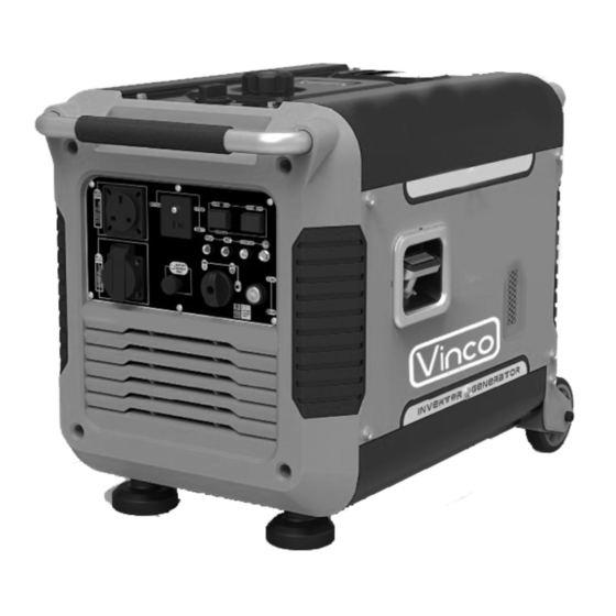
- Page 8 CONOSCENZA DEL PRODOTTO - 60156 Conoscenza del prodotto: codice 60156 con dettaglio pannello di controllo anteriore 1. Maniglia per il trasporto 2. Manopola sfiato aria tappo carburante 3. Tappo serbatoio carburante 4. Pannello di controllo 5. Manopola avviamento 6. Serbatoio olio 7.
- Page 9 CONOSCENZA DEL PRODOTTO - 60157 Conoscenza del prodotto: codice 60157 con dettaglio pannello di controllo anteriore Conoscenza del prodotto: codice 60157 con dettaglio pannello di controllo anteriore 1. Maniglia per il trasporto 2. Manopola sfiato aria tappo carburante 3. Tappo serbatoio carburante 4.
- Page 10 7. Terminale messa a terra 8. Manopola regolazione aria 9. Presa AC (corrente alternata, 230V)) OPERAZIONI DI PREPARAZIONE PRIMO UTILIZZO 10. Connettore DC (corrente continua, 12V) 11. Interruttore protezione DC Operazioni di preparazione al primo utilizzo Disimballo e controllo parti e contenuto della confezione. •...
- Page 11 Rimontare quindi il coperchio serrando le viti. Collegamento batteria (cod. 60157, opzionale) Il generatore 60157 può essere dotato in alcun Paesi di avviamento elettrico. Rimuovere il pannello laterale svitando le apposite viti ed effettuare il collegamento rispettando le polarità. Richiudere il pannello e avvitare.
- Page 12 ATTENZIONE: accompagnare il rientro della cordicella di avviamento, non rilasciarla bruscamente. Modello 60157 con avviamento elettrico. E’ possibile semplicemente girare la chiave fino ad avviamento 7. In caso di avviamento a freddo: riportare con gradualità la manopola dell’aria in posizione “Aperto”...
- Page 13 possono essere necessari almeno 5 minuti prima che ciò avvenga. 8. Se il motore, successivamente all’avviamento, si ferma e non si riavvia, controllare il livello dell’olio motore. Un livello insufficiente di olio motore genera il blocco automatico di protezione del motore notificata dall’apposita spia gialla sul frontale.
- Page 14 UTILIZZO Ruotare l’interruttore generale (rosso) su OFF (stop) e la manopola aria carburante posta sul tappo della benzina su “OFF” Spegnimento in condizioni di emergenza E’ possibile, in caso di emergenza, spegnere il generatore semplicemente agendo sull’interruttore di avviamento del motore, posizionandolo su “OFF”. Non utilizzare questa procedura se non in caso di necessità...
- Page 15 MANUTENZIONE Manutenzione del generatore Indossare sempre indumenti protettivi e guanti durante le operazioni di manutenzione. Effettuare le operazioni in un luogo rispondente alle caratteristiche di sicurezza ambientali, lontano da potenziali fonti di incendio o elettricità libera. Non effettuare la manutenzione in presenza in ambienti umidi, sotto la pioggia, la neve o altri eventi atmosferici simili, polveri o agenti chimici in sospensione nell’aria.
- Page 16 MANUTENZIONE sicurezza”. Evitare ambienti non ventilati, esposti a fiamme libere, calore o potenziali scintille elettriche. Non fumare. Tenere lontano dall’area i bambini e gli animali domestici. Indossare guanti protettivi. 1) Porre il generatore in posizione piana. 2) Aprire il tappo del carburante. 3) Utilizzare una pompa (non fornita) per estrarre in un contenitore (di tipo omologato per la conservazione del carburante) la benzina presente nel serbatoio.
- Page 17 MANUTENZIONE 4) Immergere l’elemento filtrante in olio per motori pulito e strizzarlo delicatamente per eliminare l’olio in eccesso, 5) Riposizionare il filtro dell’aria e il suo coperchio, inserendo le linguette inferiori e la linguetta di chiusura, 6) Riposizionare la copertura laterale e riavvitarla. Controllo, pulizia e cambio candela Frequenza: il cambio della candela va effettuato ogni 100 ore e in ogni caso ogni 6 mesi.
- Page 18 PROBLEMI DI FUNZIONAMENTO E SOLUZIONI L’apparecchio elettrico collegato non funziona. ITALIANO...
- Page 19 PROBLEMI DI FUNZIONAMENTO E SOLUZIONI Smaltimento Effettuare lo smaltimento del prodotto a fine vita secondo le normative. Separare gli imballaggi riciclabili in carta, cartone e plastica e smaltirli come indicato localmente. ITALIANO...
- Page 20 CONDIZIONI DI GARANZIA E ASSISTENZA Condizioni di Garanzia e Assistenza Fatte salve le “condizioni di decadenza della garanzia legale” riportate in questo libretto, il Rivenditore Vinco Products applicherà le condizioni previste dalla normativa in vigore. Vinco Srl applica una garanzia commerciale a supporto dell’attività del Rivenditore.
- Page 21 Fax. Nel caso non fosse disponibile l’utilizzo di una casella e-mail è possibile inviare la propria • richiesta di assistenza al numero: 0141 35.12.85 Assistenza Tecnica Vinco, Viale Giordana 7, 10024 Moncalieri Attenzione: il servizio di Assistenza Tecnica non è aperto al pubblico ed è contattabile al numero telefonico 0141 176.63.15 per qualsiasi necessità. ITALIANO...
- Page 22 CIRCUITO ELETTRICO ITALIANO...
- Page 23 ENGLISH...
- Page 24 Read this manual carefully before operating this machine. This manual should stay with this machine if it is sold. ENGLISH...
- Page 25 Thank you for your purchase of the inverter gasoline generator produced by our company. This manual contains the instructions on how to operate this machine. Please read it carefully before operating. Operating safely and correctly can help you get the best results. All information in this publication is based on the latest product information available at the time of printing.
-
Page 26: Safety Warnings
SAFETY WARNINGS Personal safety and property safety of you and others are very important. Please read these messages which are preceded by a symbol carefully. You WILL be KILLED or SERIOUSLY HURT if you don’t follow instructions. You CAN be KILLED or SERIOUSLY HURT if you don’t follow instructions. -
Page 27: Table Of Contents
You CAN be HURT if you don’t follow instructions. Your generator or other property could be damaged if you don’t follow instructions. CONTENTS SAFETY WARNINGS..................2 1.SAFETY INFORMATION................. 5 2. DESCRIPTION...................9 2.1 Control panel..................10 3. CONTROL FUNCTION................11 Engine switch ................... Oil warning light (red)............... - Page 28 Overload indicator light (Red)............AC pilot light (Green)................ DC protector..................Economy control switch (ECS)............Fuel tank cap..................3.8 Fuel tank cap air vent knob..............Ground (Earth) terminal..............4. PREPARATION..................fuel..................... Engine oil................... ENGLISH...
- Page 29 Pre-operation check...........…......OPERATION........…............Starting the engine........…........Stopping the engine................Alternating Current (AC) connection..........Battery Charging........…........Application range........…........6. MAINTENANCE..................Spark plug inspection................ Carburetor adjustment............... ENGLISH...
- Page 30 Engine oil replacement..............Air filter..................... 6.5 Muffler screen and spark Arrester............Fuel tank filter..................Fuel filter.................... 7. STORAGE....................33 Drain the fuel..................Engine....................8. TROUBLESHOOTING................35 Engine won’t start................Generator won’t produce power............ENGLISH...
-
Page 31: Safety Information
9. SPECIFICATIONS..................36 10. WIRING DIAGRAM................37 SAFETY INFORMATION Read and understand this owner’s manual before operating your generator. It will help you avoid accident if you get familiar with your generator’s safe operation procedure. Neve Never use it indoor Neve Never use it in a wet condition ENGLISH... - Page 32 Neve Never directly connect it to a home power system Keep Keep it at least 1 meter away Neve Never smoke when fueling ENGLISH...
- Page 33 from from inflammable Don’t spill when fueling Stop the engine before fueling Connection to a home power supply If the generator is to be connected to a home power supply as a standby, ENGLISH...
- Page 34 connection should be performed by professional electrician or by other person with proficient electrical skill. When the loads are connected to the generator, please carefully check whether the electrical connections are safe and reliable. Any improper connection may cause damage to the generator, or cause a fire. Generator Ground Circuit ENGLISH...
- Page 35 In order to prevent electric shock due to shoddy electrical appliances or wrong use of electricity, the generator must be grounded with a good-quality insulated conductor. Make sure the control panel, louver and the inverter bottom side cooling well and without chips, mud and water come in. it may damage the engine, inverter or alternator if the cooling vent blocked.
- Page 36 DISCRIPTION Carrying handle Fuel tank cap air vent knob Fuel tank cap Control panel Recoil starter Oil filler cap ENGLISH...
-
Page 37: Control Panel
Louver Muffler Control panel ENGLISH... -
Page 38: Control Function
Oil warning light AC pilot light Overload indicator light Economy control switch (Black) Engine switch (Red) Fuel cock knob Ground (earth) terminal Choke knob AC receptacle DC receptacle ⑪ DC protector CONTROL FUNCTION 3.1 Engine switch Engine switch “STOP”; ENGLISH... - Page 39 Ignition circuit is switched off. The engine will not run. Engine switch “ON”; Ignition circuit is switched on. The engine can be running. Oil warning light (yellow) When the oil level falls below the lower level, the oil warning light comes on and then the engine stops automatically.
- Page 40 will stay on, but the engine will not stop running. When the overload indicator light comes on and power generation stops, proceed as follows: 1. Turn off any connected electric devices and stop the engine. 2. Reduce the total wattage of connected appliance into the rated output.
- Page 41 being connected to the generator is operating and current above the rated flows. To use this equipment again, turn on DC protector by pressing its button to “ON” “ON” Direct current is output. “OFF” Direct current is not output. Reduce the load of the connected electric device below the specified rated output of the generator if the DC protector turns off.
- Page 42 “OFF” When the ECS switch is turned to “OFF”, the engine runs at the rated speed (4500r/min) regardless of whether is a load connected or not. Tip: The ECS must be turned to “OFF” when using electric devices that require a large starting current, such as a compressor of a submergible pump.
- Page 43 Ground (Earth) terminal connects the earth line for prevention of electric shock. When the electric device is earthed, always the generator must be earthed. PREPARATION Fuel • Fuel is highly flammable and poisonous. ENGLISH...
- Page 44 Check “SAFETY INFORMA-TION” carefully before filling. • Do not overfill the fuel tank, otherwise it may overflow when the fuel warms up and expands. • After fill the fuel, make sure the fuel tank cap is tightened securely. • Immediately wipe off spilled fuel with a clean, dry, soft cloth, since fuel may deteriorate painted surfaces or plastic parts.
- Page 45 Engine oil The generator has been shipped without engine oil. Do not start the engine till fill with the sufficient engine oil. 1. Place the generator on a level surface. 2. Remove the screws , remove the cover 3. Remove the oil filler cap. 4.
- Page 46 Engine oil quantity: 0.35 L PRE-OPERATION CHECK If any item in the Pre-operation check is not working properly, have it inspected and repaired before operating the generator. The condition of a generator is the owner’s responsibility. Vital components can start to deteriorate quickly and unexpectedly, even if the generator unused.
- Page 47 Engine oil (See page 17) • Check oil level in engine. • If necessary, add recommended oil to specified level. • Check generator for oil leakage. The point where abnormality was recognized by use • Check operation. • If necessary, add recommended oil to specified level. •...
- Page 48 • Do not tilt the generator when adding engine oil. This could result in over filling and damage to the engine. TIP: The generator can be used with the rated output load at standard atmospheric conditions. “Standard atmospheric conditions” Ambient temperature 25 Barometric pressure 100kPa Relative humidity 30% The output of the generator varies due to change temperature, altitude (lower...
- Page 49 2. Turn the air vent knob to “ON” 4. Turn the fuel cock knob to “ON”. 4. Turn the engine switch (Red) to “ON”. 5. Pull the choke knob fully out. TIP: The choke is not required to start a warm engine. Push the choke knob in to the original position.
- Page 50 TIP: When starting the engine, with the ESC “ON”, and there is no load on the generator: • In ambient temperature below 0 (32 ), the engine will run at the rated r/min (4500r/min) for 5 minutes to warm up the engine. •...
- Page 51 Alternating Current (AC) connection Be sure any electric devices are turned off before plugging them in. • Be sure all electric devices including the lines and plug connections are in good condition before connection to the generator. • Be sure the total load is within generator rated output. •...
- Page 52 TIP: The ECS must be turned to “OFF” to increase engine speed to rated rpm. If the generator is connected to multiple loads or electricity consumers, please remember to first connect the one with the highest starting current, and last connect the one with the lowest starting current. Battery Charging TIP: •...
- Page 53 • Be sure the ESC is turned off while charging the battery. • Be sure to connect the red battery charger lead to the positive (+) battery terminal, and connect the black lead to the negative (-) battery terminal. Do not reverse these positions.
- Page 54 Never smoke or make and break connections at the battery while charging. Sparks may ignite the battery gas. Battery electrolyte is poisonous and dangerous, causing severe burns, etc. contains sulfuric (sulphuric) acid. Avoid contact with skin, eyes or clothing. Antidote: EXTERNAL - Flush with water.
- Page 55 TIP: • Application wattage indicates when each device is used by itself.• The simultaneous usage of AC and DC power is possible but total wattage should not exceed the rated output. The overload indicator light comes on when total wattage exceeds the application range.
- Page 56 generator. • When supplying precision equipment, electronic controllers, PCs, Electronic computers, microcomputer based equipment or battery chargers, keep the generator a sufficient distance away to prevent electrical interference from the engine. Also ensure that electrical noise from the engine does not interfere with any other electrical devices located near the generator.
- Page 57 • If the gasoline engine frequently works under high temperature or heavy load, change the oil every 25 hours. • If the engine frequently works under dusty or other severe circumstances, clean the air filter element every 10 hours; If necessary, change the air filter ENGLISH...
- Page 58 element every 25 hours. • The maintenance period and the exact time (hour), the one which comes first should govern. • If you have missed the scheduled time to maintain your engine, do it as soon as possible. Stop the engine before servicing. Put the engine on a level surface and remove the spark plug cap to prevent the engine from starting.
- Page 59 2. Insert the handlebar into the tool and turn it counterclockwise tore move the spark plug. 3. Check for discoloration and remove the carbon. The porcelain insulator around the center electrode of spark plug should be a medium-to-light tan color. 4.
- Page 60 Carburetor adjustment The carburetor is a vital part of the engine. Adjusting should be left to our company authorized dealer with the professional knowledge, specialized date, and equipment to do so properly. Engine oil replacement Avoid draining the engine oil immediately after stopping the engine. The oil is hot and should be handled with care to avoid burns.
- Page 61 filling and damage to the engine. 6. Add engine oil to the upper level. Recommended engine oil: SAE SJ 15W-40 Recommended engine oil grade: API Service SE type or higher Engine oil quantity: 0.35L 7. Wipe the cover clean, and wipe up any spilled oil. Be sure no foreign material enters the crankcase.
- Page 62 3. Remove the foam element 4. Wash the foam element in solvent and dry it. 5. Oil the foam element and squeeze out excess oil. The foam element should be wet but not dripping. Do not wring out the foam element when squeezing it. This could cause it to tear.
- Page 63 body or clothing during inspection or repair. 1. Remove the screws , and then pull outward on the areas of the cover shown. 2. Loosen the bolt and then remove the muffler cap , the muffler screen and spark arrester 3.
- Page 64 TIP: Align the spark arrester projection with the hole in the muffler pipe. 6. Install the muffler screen and the muffler cap. 7. Install the cover and tighten the screws. Fuel tank filter Never use the gasoline while smoking or in the vicinity of an open flame.
- Page 65 2. Hold and move up the clamp , then take off the hose from the tank. 3. Take out the fuel filter 4. Clean the filter with gasoline. 5. Dry the filter and put it bank into tank. 6. Install the hose and clamp, then open the fuel valve to check whether it is leak 7.
- Page 66 2. Remove the fuel tank cap, remove the filter. Extract the fuel from the fuel tank into an approved gasoline container. Then, install the fuel tank cap. Fuel highly flammable poisonous. Check “SAFETY INFORMATION” (See page 5) carefully. Immediately wipe off spilled fuel with a clean, dry, soft cloth, since fuel may deteriorate painted surfaces or plastic parts.
- Page 67 7. Tighten the drain screw. 8. Install the cover and tighten the screws. 9. Turn the fuel tank cap air vent knob to “OFF” after the engine has completely cools down. Engine Perform the following steps to protect the cylinder, piston ring, etc. from corrosion.
- Page 68 1. Fuel systems No fuel supplied to combustion chamber. No fuel in tank…Supply fuel. Fuel in tank….Fuel tank cap air vent knob and fuel cock knob to “ON” Clogged fuel filter …. Clean fuel filter. Clogged carburetor…. Clean carburetor. 2. Engine oil system Insufficient Oil level is low….
- Page 70 La presente dichiarazione di conformità è rilasciata sotto la responsabilità esclusiva del Fabbricante Fascicolo tecnico costituito e detenuto da Daniele Nossa, c/o Vinco S.r.l., Piazza Statuto 1 – 14100 Asti DENOMINAZIONE, FUNZIONE E TIPO: GENERATORE DI CORRENTE INVERTER (GRUPPO ELETTROGENO) CODICE: 60157 / 65157 LOTTO: rif.
- Page 71 Il servizio è aggiuntivo e non sostitutivo rispetto a quello di cui al punto 1 e si applica solo alle tipologie di prodotti previste da Vinco. Invitiamo a contattare Vinco allo scopo di verificare se il prodotto possa usufruire di questo servizio.
- Page 72 Importato e Distribuito da Vinco S.r.l. - P.zza Statuto, 1 – 14100 Asti (AT) ITALY Tel.0141.351284 PRODOTTO DESTINATO AD USO HOBBISTICO RICAMBI E ASSISTENZA Viale Giordana 7 - 10024 Moncalieri (TO) - TEL. 0141-1766315 MADE IN CHINA...
Need help?
Do you have a question about the 60157 and is the answer not in the manual?
Questions and answers