Table of Contents
Advertisement
Quick Links
User's Manual
WIP181AM
AMIT
Wireless Router /
無線路由器
Copyright
The contents of this publication may not be reproduced in any part or as a whole, stored, transcribed in
an information retrieval system, translated into any language, or transmitted in any form or by any
means, mechanical, magnetic, electronic, optical, photocopying, manual, or otherwise, without the
prior written permission.
Trademarks
All products, company, brand names are trademarks or registered trademarks of their respective
companies. They are used for identification purpose only. Specifications are subject to be changed
without prior notice.
FCC Interference Statement
This equipment has been tested and found to comply with the limits for a Class B digital device
pursuant to Part 15 of the FCC Rules. These limits are designed to provide reasonable protection
against radio interference in a commercial environment. This equipment can generate, use and radiate
radio frequency energy and, if not installed and used in accordance with the instructions in this manual,
may cause harmful interference to radio communications. Operation of this equipment in a residential
area is likely to cause interference, in which case the user, at his own expense, will be required to take
whatever measures are necessary to correct the interference.
CE Declaration of Conformity
This equipment complies with the requirements relating to electromagnetic compatibility, EN
55022/A1 Class B.
The specification is subject to change without notice.
1
Advertisement
Table of Contents

Related Manuals for Amit WIP181AM


Summary of Contents for Amit WIP181AM
- Page 1 User’s Manual WIP181AM AMIT Wireless Router / 無線路由器 Copyright The contents of this publication may not be reproduced in any part or as a whole, stored, transcribed in an information retrieval system, translated into any language, or transmitted in any form or by any means, mechanical, magnetic, electronic, optical, photocopying, manual, or otherwise, without the prior written permission.
-
Page 2: Table Of Contents
Table of Contents Chapter 1 Introduction ................3 Functions and Features ................ 3 Packing List ..................5 Chapter 2 Hardware Installation ............... 6 2.1 Panel Layout .................. 6 2.2 Procedure for Hardware Installation..........8 Chapter 3 Network Settings and Software Installation......9 3.1 Make Correct Network Settings of Your Computer....... -
Page 3: Chapter 1 Introduction
Congratulations on your purchase of this outstanding Wireless Broadband Router. This product is specifically designed for Small Office and Home Office needs. It provides a complete SOHO solution for Internet surfing, and is easy to configure and operate even for non-technical users. Instructions for installing and configuring this product can be found in this manual. - Page 4 Wireless functions High speed for wireless LAN connection Up to 80Mbps data rate by incorporating Orthogonal Frequency Division Multiplexing (OFDM). Roaming Provides seamless roaming within the IEEE 802.11b (11M) and IEEE 802.11g (54M) and IEEE 802.11n (6.5M) WLAN infrastructure. WDS(Wireless Distribution System): It is a system that enables the interconnection of access points wirelessly.
-
Page 5: Packing List
DoS Attack Detection Supported When this feature is enabled, the router will detect and log the DoS attack comes from the Internet. Qos(Quality of Service) Provide different priority to different users or data flows, or guarantee a certain level of performance. -
Page 6: Chapter 2 Hardware Installation
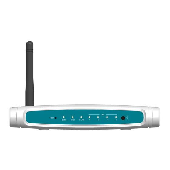
2.1 Panel Layout 2.1.1. Front Panel Figure 2-1 Front Panel LED: Ports: Port Description Power inlet the port where you will connect your cable (or DSL) modem or Ethernet router. Port 1-4 the ports where you will connect networked computers and other devices. - Page 7 2.1.2. Rear Panel Figure 2-2 Rear Panel LED: Function Color Status Description System Status is flashed once per second to indicate system is Status Green Blinking status alive. WAN port Green The WAN port is linked. activity Blinking The WAN port is sending or receiving data. Wireless WLAN Green...
-
Page 8: Procedure For Hardware Installation
2.2 Procedure for Hardware Installation 2. Decide where to place your Wireless Broadband Router You can place your Wireless Broadband Router on a desk or other flat surface, or you can mount it on a wall. For optimal performance, place your Wireless Broadband Router in the center of your office (or your home) in a location that is away from any potential source of interference, such as a metal wall or microwave oven. -
Page 9: Chapter 3 Network Settings And Software Installation
To use this product correctly, you have to properly configure the network settings of your computers and install the attached setup program into your MS Windows platform (Windows 95/98/NT/2000). 3.1 Make Correct Network Settings of Your Computer The default IP address of this product is 192.168.123.254, and the default subnet mask is 255.255.255.0. -
Page 10: Chapter 4 Configuring Wireless Broadband Router
This product provides Web based configuration scheme, that is, configuring by your Web browser, such as Netscape Communicator or Internet Explorer. This approach can be adopted in any MS Windows, Macintosh or UNIX based platforms. -
Page 11: Login To Configure From Wizard
4.1 Login to Configure from Wizard Activate your browser, and disable the proxy or add the IP address of this product into the exceptions. Then, type this product’s IP address in the Location (for Netscape) or Address (for IE) field and press ENTER. For example: http://192.168.123.254. After the connection is established, you will see the web user interface of this product. - Page 12 If the user finishes those steps and the router shows as below. It means that customers can enjoy Internet.
-
Page 13: Status
4.2 Status This option provides the function for observing this product’s working status: A. WAN Port Status. If the WAN port is assigned a dynamic IP, there may appear a “Renew” or “Release” button on the Sidenote column. You can click this button to renew or release IP manually. B. -
Page 14: Basic Setting
4.4 Basic Setting Please Select “Advanced Setup” to Setup... - Page 15 4.4.1 Primary Setup – WAN Type, Virtual Computers Press “Change” This option is primary to enable this product to work properly. The setting items and the web appearance depend on the WAN type. Choose correct WAN type before you start. 1.
- Page 16 C. Dynamic IP Address with Road Runner Session Management.(e.g. Telstra BigPond) D. PPP over Ethernet: Some ISPs require the use of PPPoE to connect to their services. E. PPTP: Some ISPs require the use of PPTP to connect to their services. F.
- Page 17 Auto-Reconnect(Always-on):The device will link with ISP until the connection is established. Manually :The device will not make the link until someone clicks the connect-button in the Staus-page. 4.4.1.5 PPTP First, Please check your ISP assigned and Select Static IP Address or Dynamic IP Address. My IP Address and My Subnet Mask: the private IP address and subnet mask your ISP assigned to you.
- Page 18 to you. Server IP Address: the IP address of the PPTP server. PPTP Account and Password: the account and password your ISP assigned to you. If you don't want to change the password, keep it empty. Connection ID: optional. Input the connection ID if your ISP requires it. Maximum Idle Time: the time of no activity to disconnect your PPTP session.
- Page 19 4.4.1.7 Virtual Computers(Only for Static and dynamic IP address Wan type) Virtual Computer enables you to use the original NAT feature, and allows you to setup the one-to-one mapping of multiple global IP address and local IP address. • Global IP: Enter the global IP address assigned by your ISP. •...
- Page 20 4.4.2 DHCP Server Press “More>>” DHCP Server: Choose “Disable” or “Enable.” Lease time: This is the length of time that the client may use the IP address it has been Assigned by dhcp server. IP pool starting Address/ IP pool starting Address: Whenever there is a request, the DHCP server will automatically allocate an unused IP address from the IP address pool to the requesting computer.
- Page 21 4.4.3 Wireless Setting, 802.1X setting and WDS Wireless settings allow you to set the wireless configuration items. Wireless : The user can enable or disalbe wireless function. Network ID (SSID): Network ID is used for identifying the Wireless LAN (WLAN). Client stations can roam freely over this product and other Access Points that have the same Network ID.
- Page 22 There are several security types to use: WEP : When you enable the 128 or 64 bit WEP key security, please select one WEP key to be used and input 26 or 10 hexadecimal (0, 1, 2…8, 9, A, B…F) digits. 802.1X Check Box was used to switch the function of the 802.1X.
- Page 23 If ASCII, the length of pre-share key is from 8 to 63. 2. Fill in the key, Ex 12345678 Check Box was used to switch the function of the WPA. When the WPA function is enabled, the Wireless user must authenticate to this router first to use the Network service. RADIUS Server IP address or the 802.1X server’s domain-name.
- Page 24 WPA2(AES) Check Box was used to switch the function of the WPA. When the WPA function is enabled, the Wireless user must authenticate to this router first to use the Network service. RADIUS Server IP address or the 802.1X server’s domain-name. Select RADIUS Shared Key If you select HEX, you have to fill in 64 hexadecimal (0, 1, 2…8, 9, A, B…F) digits If ASCII, the length of Pre-share key is from 8 to 63.
- Page 25 WPA/WPA2 Check Box was used to switch the function of the WPA. When the WPA function is enabled, the Wireless user must authenticate to this router first to use the Network service. RADIUS Server The router will detect automatically which Security type(Wpa-psk version 1 or 2) the client uses to encrypt.
- Page 26 WPS(WiFi Protection Setup) WPS is WiFi Protection Setup which is similar to WCN-NET and offers safe and easy way in Wireless Connection.
- Page 27 WDS(Wireless Distribution System) WDS operation as defined by the IEEE802.11 standard has been made available. Using WDS it is possible to wirelessly connect Access Points, and in doing so extend a wired infrastructure to locations where cabling is not possible or inefficient to implement.
- Page 28 4.4.4 Change Password You can change Password here. We strongly recommend you to change the system password for security reason.
-
Page 29: Forwarding Rules
4.5 Forwarding Rules... - Page 30 4.5.1 Virtual Server This product’s NAT firewall filters out unrecognized packets to protect your Intranet, so all hosts behind this product are invisible to the outside world. If you wish, you can make some of them accessible by enabling the Virtual Server Mapping. A virtual server is defined as a Service Port, and all requests to this port will be redirected to the computer specified by the Server IP.
- Page 31 4.5.2 Special AP Some applications require multiple connections, like Internet games, Video conferencing, Internet telephony, etc. Because of the firewall function, these applications cannot work with a pure NAT router. The Special Applications feature allows some of these applications to work with this product. If the mechanism of Special Applications fails to make an application work, try setting your computer as the DMZ host instead.
- Page 32 4.5.3 Miscellaneous Items IP Address of DMZ Host DMZ (DeMilitarized Zone) Host is a host without the protection of firewall. It allows a computer to be exposed to unrestricted 2-way communication for Internet games, Video conferencing, Internet telephony and other special applications. NOTE: This feature should be used only when needed.
-
Page 34: Security Settings
4.6 Security Settings... - Page 35 4.6.1 Packet Filter Packet Filter enables you to control what packets are allowed to pass the router. Outbound filter applies on all outbound packets. However, Inbound filter applies on packets that destined to Virtual Servers or DMZ host only. You can select one of the two filtering policies: 1.
- Page 36 prefix "T" or "U" to specify TCP or UDP protocol. For example, T80, U53, U2000-2999. No prefix indicates both TCP and UDP are defined. An empty implies all port addresses. Packet Filter can work with Scheduling Rules, and give user more flexibility on Access control. For Detail, please refer to Scheduling Rule.
- Page 37 Example 2: (1.2.3.100-1.2.3.119) They can do everything except read net news (port 119) and transfer files via FTP (port 21) Others are all allowed. After Inbound Packet Filter setting is configured, click the save button. Outbound Filter: To enable Outbound Packet Filter click the check box next to Enable in the Outbound Packet Filter field.
- Page 38 (149.161.123.100-149.161.123.149) They are allowed to send mail (port 25), receive mail (port 110), and browse Internet (port 80); port 53 (DNS) is necessary to resolve the domain name. (149.161.123.10-149.161.123.20) They can do everything (block nothing) Others are all blocked.
- Page 39 Example 2: (149.161.123.100 and 149.161.123.119) They can do everything except read net news (port 119) and transfer files via FTP (port 21) Others are allowed After Outbound Packet Filter setting is configured, click the save button.
- Page 40 4.6.2 Domain Filter Domain Filter Let you prevent users under this device from accessing specific URLs. Domain Filter Enable Check if you want to enable Domain Filter. Log DNS Query Check if you want to log the action when someone accesses the specific URLs. Privilege IP Addresses Range Setting a group of hosts and privilege these hosts to access network without restriction.
- Page 41 In this example: 1. URL include “www.msn.com” will be blocked, and the action will be record in log-file. 2. URL include “www.sina.com” will not be blocked, but the action will be record in log-file. 3. URL include “www.google.com” will be blocked, but the action will not be record in log-file. IP address X.X.X.1~ X.X.X.20 can access network without restriction.
- Page 42 4.6.3 URL Blocking URL Blocking will block LAN computers to connect to pre-defined Websites. The major difference between “Domain filter” and “URL Blocking” is Domain filter require user to input suffix (like .com or .org, etc), while URL Blocking require user to input a keyword only. In other words, Domain filter can block specific website, while URL Blocking can block hundreds of websites by simply a keyword.
- Page 43 In this example: 1. URL include “msn” will be blocked, and the action will be record in log-file. 2. URL include “sina” will be blocked, but the action will be record in log-file 3. URL include “cnnsi” will not be blocked, but the action will be record in log-file. 4.
- Page 44 4.6.4 MAC Address Control MAC Address Control allows you to assign different access right for different users and to assign a specific IP address to a certain MAC address. MAC Address Control Check “Enable” to enable the “MAC Address Control”. All of the settings in this page will take effect only when “Enable”...
- Page 45 addresses are not in the "Control table", to associate to the wireless LAN. Control table "Control table" is the table at the bottom of the "MAC Address Control" page. Each row of this table indicates the MAC address and the expected IP address mapping of a client.
- Page 46 Example: In this scenario, there are three clients listed in the Control Table. Clients 1 and 2 are wireless, and client 3 is wired. 1.The "MAC Address Control" function is enabled. 2."Connection control" is enabled, and all of the wired and wireless clients not listed in the "Control table"...
- Page 47 address not specified in the Control table is denied to associate to the wireless LAN. Client 3 is a wired client and so is not affected by Association control. 4.6.5 Miscellaneous Items Remote Administrator Host/Port In general, only Intranet user can browse the built-in web pages to perform administration task. This feature enables you to perform administration task from remote host.
-
Page 48: Advanced Settings
4.7 Advanced Settings 4.7.1 System Time... - Page 49 Get Date and Time by NTP Protocol Selected if you want to Get Date and Time by NTP Protocol. Time Server Select a NTP time server to consult UTC time Time Zone Select a time zone where this device locates. Set Date and Time manually Selected if you want to Set Date and Time manually.
- Page 50 This page support two methods to export system logs to specific destination by means of syslog(UDP) and SMTP(TCP). The items you have to setup including: IP Address for Syslog Host IP of destination where syslogs will be sent to. Check Enable to enable this function. E-mail Alert Enable Check if you want to enable Email alert (send syslog via email).
- Page 51 4.7.3 Dynamic DNS To host your server on a changing IP address, you have to use dynamic domain name service (DDNS). So that anyone wishing to reach your host only needs to know the name of it. Dynamic DNS will map the name of your host to your current IP address, which changes each time you connect your Internet service provider.
- Page 52 You will get this information when you register an account on a Dynamic DNS server. Example: After Dynamic DNS setting is configured, click the save button.
- Page 53 4.7.4 SNMP Setting In brief, SNMP, the Simple Network Management Protocol, is a protocol designed to give a user the capability to remotely manage a computer network by polling and setting terminal values and monitoring network events. Enable SNMP You must check either Local or Remote or both to enable SNMP function. If Local is checked, this device will response request from LAN.
- Page 54 4.7.5 Routing Routing Tables allow you to determine which physical interface address to use for outgoing IP data grams. If you have more than one routers and subnets, you will need to enable routing table to allow packets to find proper routing path and allow different subnets to communicate with each other. Routing Table settings are settings used to setup the functions of static.
- Page 55 Example: Configuration on NAT Router Destination SubnetMask Gateway Enabled ˇ 192.168.1.0 255.255.255.0 192.168.123.216 ˇ 192.168.0.0 255.255.255.0 192.168.123.103 So if, for example, the client3 wanted to send an IP data gram to 192.168.0.2, it would use the above table to determine that it had to go via 192.168.123.103 (a gateway), And if it sends Packets to 192.168.1.11 will go via 192.168.123.216 Each rule can be enabled or disabled individually.
- Page 56 4.7.6 Schedule Rule You can set the schedule time to decide which service will be turned on or off. Select the “enable” item. Press “Add New Rule” You can write a rule name and set which day and what time to schedule from “Start Time” to “End Time”.
- Page 57 Schedule Enable Selected if you want to Enable the Scheduler. Edit To edit the schedule rule. Delete To delete the schedule rule, and the rule# of the rules behind the deleted one will decrease one automatically. Schedule Rule can be apply to Virtual server and Packet Filter, for example: Exanple1: Virtual Server –...
-
Page 59: Qos Rule
4.7.7 Qos Rule Local IP: Please input Client IP,ex192.168.12.33. Remote Priority: Please input Global IP and port,ex:168.96.2.3 and port 21... -
Page 60: Toolbox
4.8 Toolbox 4.8.1 System Log You can View system log by clicking the View Log button... - Page 61 4.8.2 Firmware Upgrade You can upgrade firmware by clicking Firmware Upgrade button. 4.8.3 Backup Setting You can backup your settings by clicking the Backup Setting button and save it as a bin file. Once you want to restore these settings, please click Firmware Upgrade button and use the bin file you saved. 4.8.4 Reset to default You can also reset this product to factory default by clicking the Reset to default button.
- Page 62 4.8.5 Reboot You can also reboot this product by clicking the Reboot button. 4.8.6 Miscellaneous Items MAC Address for Wake-on-LAN Wake-on-LAN is a technology that enables you to power up a networked device remotely. In order to enjoy this feature, the target device must be Wake-on-LAN enabled and you have to know the MAC address of this device, say 00-11-22-33-44-55.
- Page 63 Figure 1: Testing Environment (Use Windows 2000 Radius Server) 1 Equipment Details PC1: Microsoft Windows XP Professional without Service Pack 1. AMIT 531C Wireless Cardbus:3.0.3.0 Driver version: PC2: Microsoft Windows XP Professional with Service Pack 1a or latter. AMIT 561C Wireless Cardbus:1.0.1.0 Driver version: 1.7.29.0 (Driver date: 10.20.2001)
-
Page 64: Appendix A 802.1X Setting
1.Enable DHCP server. 2.WAN setting: static IP address. 3.LAN IP address: 192.168.123.254/24. 4.Set RADIUS server IP. 5.Set RADIUS server shared key. 6.Configure WEP key and 802.1X setting. The following test will use the inbuilt 802.1X authentication method such as ,EAP_TLS, PEAP_CHAPv2(Windows XP with SP1 only), and PEAP_TLS(Windows XP with SP1 only) using the Smart Card or other Certificate of the Windows XP Professional. - Page 65 4. We will change EAP type to fit the variable test condition. Figure 2: Enable IEEE 802.1X access control...
- Page 66 Figure 3: Smart card or certificate properties 4. Windows 2000 RADIUS server Authentication testing: 4.1DUT authenticate PC1 using certificate. (PC2 follows the same test procedures.) 1. Download and install the certificate on PC1. (Fig 4) 2. PC1 choose the SSID of DUT as the Access Point. 3.
- Page 67 Figure 4: Certificate information on PC1 Figure 5: Authenticating...
- Page 68 Figure 6: Authentication success 4.2DUT authenticate PC2 using PEAP-TLS. 1. PC2 choose the SSID of DUT as the Access Point. 2. Set authentication type of wireless client and RADIUS server both to PEAP_TLS. 3. Disable the wireless connection and enable again. 4.The DUT will send the user's certificate to the RADIUS server, and then send the message of authentication result to PC2.
-
Page 69: Appendix B Wpa-Psk And Wpa
Wireless Router: LAN IP: 192.168.123.254 WAN IP: 192.168.122.216 Radius Server: 192.168.122.1 UserA : XP Wireless Card:Ti-11g Tool: Odyssey Client Manager Refer to: www.funk.com Download: http://www.funk.com/News&Events/ody_c_wpa_preview_pn.asp Or Another Configuration: PA-PSK... - Page 70 In fact, it is not necessary for this function to authenticate by Radius Server, the client and wireless Router authenticate by themselves. Method1: 1. Go to the Web manager of Wireless Router to configure, like below: 2. Go to Odyssey Client Manager, first choose “Network” Before doing that, you should verify if the software can show the wireless card.
- Page 71 4. Back to Connection: Then Select “Connect to network” You will see: Method2: 1. First, patch windows XP and have to install “Service package 1”...
- Page 72 Patch: http://www.microsoft.com/downloads/details.aspx?displaylang=en&FamilyID=5039ef4a-61e0-4c44 -94f0-c25c9de0ace9 2. Then reboot. 3. Setting on the router and client: Router: Client: Go to “Network Connection” and select wireless adapter. Choose “View available Wireless Networks” like below: Advanced choose “123kk”...
- Page 73 WPA: For this function, we need the server to authenticate. This function is like 802.1x. The above is our environment: Method 1: 1. The UserA or UserB have to get certificate from Radius, first. http://192.168.122.1/certsrv account : fae1 passwd : fae1 2.
- Page 74 4. Go to Odyssey Client Manager, choose “Profiles” and Setup Profile name as “1” Login name and password are fae1 and fae1. Remember that you get certificate from Radius in Step1.
- Page 75 5. Then Choose “certificate” like above.
- Page 76 6. Then go to Authentication and first Remove EAP/ TLS and Add EAP/TLS again.
- Page 77 7. Go “Network” and Select “1” and ok...
- Page 78 8. Back to Connection and Select “123kk. If successfully, the wireless client has to authenticate with Radius Server, like below: 9.Result: Method 2: 1. The UserA or UserB have to get certificate from Radius,first. http://192.168.122.1/certsrv account:fae1 passwd:fae1...
- Page 79 2. Then Install this certificate and finish. 3. Setting on the router and client: Router:...
- Page 80 Client: Go to “Network Connection” and select wireless adapter. Choose “View available Wireless Networks” like below: Advanced choose “123kk” Select “WirelessCA and Enable” in Trusted root certificate authority: Then, if the wireless client wants to associate, it has to request to authenticate.
-
Page 81: Appendix C Faq And Troubleshooting
What can I do when I have some trouble at the first time? 1. Why can I not configure the router even if the cable is plugged in the ports of Router and the led is also light? A: First, make sure that which port is plugged. If the cable is in the Wan port, please change to plug in Lan port 1 or Lan port 4: Then, please check if the Pc gets ip address from Router. - Page 82 the led is light? A: First, please check Status Led. If the device is normal, the led will blink per second. If not, please check How blinking Status led shows. There are many abnormal symptoms as below: Status Led is bright or dark in work: The system hanged up .Suggest powering off and on the router.
- Page 83 Step2: Open the command mode and input “cmd” then check if the router replies to ping 192.168.123.254 Step3:Please use the exe-file of fw and click as below: Then click” Upgrade” if necessary, please input password ”admin” .Then reset to default and refer to Q1 How to connect Router.
-
Page 84: How Do I Connect Router By Using Wireless
A: Make sure that the network cable from DSL or Cable modem is plugged in Wan port of Router and that the network cable from Lan port of router is plugged in Ethernet adapter. Then, please check which wan type you use. If you are not sure, please call the isp. Then please go to this page to input the information isp is assigned. - Page 85 About wireless client, you will see wireless icon: Then click and will see the ap list that wireless client can be accessed: If the client can not access your wireless router, please refresh network list again. However, I still can not fine the device which ssid is “default”, please refer to Q3.
- Page 86 2.When I use AES encryption of WPA-PSK to connect even if I input the correct pre-share key? A: First, you must check if the driver of wireless client supports AES encryption. Please refer to the below: If SSID is default and click “Properties” to check if the driver of wireless client supports AES encryption.
- Page 87 3.When I use wireless to connect the router, but I find the signal is very low even if I am close to the router? A: Please check if the wireless client is normal, first. If yes, please send the unit to the seller and verify What the problem is.
- Page 88 第十二條 型式認證合格之低功率射頻電機,非經許可,公司、商號或 使用者均不得擅自變更頻率、加大功率或變更原設計之特性 及功能。 第十四條 低功率射頻電機之使用不得影響飛航安全及干擾合法通 信;經發現有干擾現象時,應立即停用,並改善至無干擾時 方得繼續使用。 前項合法通信,指依電信法規定作業之無線電通信。 低功率射頻電機須忍受合法通信或工業、科學及醫療用電波 輻射性電機設備之干擾。...
Need help?
Do you have a question about the WIP181AM and is the answer not in the manual?
Questions and answers