
Subscribe to Our Youtube Channel
Related Manuals for Amit AIPQB1215WA61/01


Summary of Contents for Amit AIPQB1215WA61/01
- Page 1 AIPQB1215WA61/01 TFT panel for rolling stock Operation manual Version 1.01 aipqb1215wa6101_g_en_101...
- Page 2 AIPQB1215WA61/01 AMiT, spol. s r. o. does not provide any warranty concerning the contents of this publication and reserves the right to change the documentation without obligation to inform anyone or any authority about it. This document can be copied and redistributed under following conditions: 1.
-
Page 3: Table Of Contents
AIPQB1215WA61/01 Contents History of revisions ..................4 Related documentation ................... 4 Introduction ..................5 Technical parameters ................6 2.1. Dimensions ..................... 9 2.2. Connector location ..................9 2.3. Location of mounting holes ................10 2.4. Recommended drawing symbol ..............10 2.5. -
Page 4: History Of Revisions
AIPQB1215WA61/01 History of revisions Document name: aipqb1215wa6101_g_en_101.pdf Author: Ondřej Rott Revision Date Changes 7. 4. 2015 New document 1. 9. 2015 Changes in 2. Technical parameters, 2.4. Recommended drawing symbol, 4. Power supply, 5. Digital inputs / outputs, 6. Communication lines and peripherals... -
Page 5: Introduction
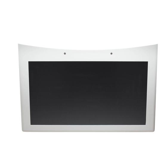
AIPQB1215WA61/01 1. Introduction AIPQB1215WA61/01 is a TFT panel for rolling stock. 21.5“ TFT display, resolution 1920 × 1080, LED backlight Basic features CPU MSC Q7-BT-15-2201I Linux operating system 2 × USB 1 × RS422 1 × Audio output ... -
Page 6: Technical Parameters
AIPQB1215WA61/01 2. Technical parameters CPU module Module MSC Q7-BT-15-2201I Processor Intel Atom E3815 Single-Core 1.46 GHz, 5 W TDP SDRAM 2 GB DDR3L FLASH memory 4 GB eMMC Flash TFT, 21.5“ Display Type (1920 × 1080) pixels Resolution Number of faulty pixels Max. - Page 7 AIPQB1215WA61/01 Log. 0 output voltage Log. 1 output voltage Power supply voltage Maximum output current 0.5 A Galvanic separation Yes, 500 V AC / 1 minute *) Connection point WAGO 769-106/021-000 Wire cross section 0.75 mm to 1.5 mm Note *) Insulation must not be used for dangerous voltage separation.
- Page 8 AIPQB1215WA61/01 Dimensions (w × h × d) (554 × 360 × 158) mm Package dimensions (w × h × d) (580 × 380 × 180) mm Dangerous Unit overall mass of plastics 1283 g materials Included mass of self-extinguishing 1283 g...
-
Page 9: Dimensions
AIPQB1215WA61/01 2.1. Dimensions 61,7 553,8 157,8 Fig. 1 - AIPQB1215WA61/01 dimensions 2.2. Connector location Fig. 2 - Location of AIPQB1215WA61/01 connectors 9/36 aipqb1215wa6101_g_en_101... -
Page 10: Location Of Mounting Holes
Mounting holes are intended to be used with 4 M8 screws. 4 x O 9 350,0 Fig. 3 - Location and dimensions of AIPQB1215WA61/01 mounting holes 2.4. Recommended drawing symbol Following drawing symbol is recommended for AIPQB1215WA61/01 TFT... -
Page 11: Type Label
AIPQB1215WA61/01 2.5. Type label The unit has a type label attached to its rear side. Included data are summarized in the table: Description Data Note – Logo AMiT Producer logo – QR code Product QR code TYPE AIPQB1215WA61/01 Unit type designation... - Page 12 AIPQB1215WA61/01 Fig. 6 - Location of type label (illustrative picture) aipqb1215wa6101_g_en_101 12/36...
-
Page 13: Conformity Assessment
AIPQB1215WA61/01 3. Conformity assessment The equipment meets the claims of Czech government decree NV616/2006; the compliance assessment has been performed in accordance with harmonized standard EN 50121-3-2:2006 in obligatory scope given by EN 50155:2007. Tested in accordance Type of test... -
Page 14: Other Tests
AIPQB1215WA61/01 3.1. Other tests This product was assessed and approved for use in railway applications according to standards: Tested in accordance Type of test Classification with standard Railway applications – Electronic EN 50155:2007 Complies equipment used on rolling stock. Railway applications – Electromagnetic... -
Page 15: Power Supply
TFT panel is installed. Connector location AUDIO + RS422 Fig. 7 - Location of AIPQB1215WA61/01 power supply connector Legend Number Meaning Connector X1 – Power supply 4.1. Turning TFT panel on and off TFT panel is turned on after connection of power supply to Vcc and GND terminals and activation by SB signal. -
Page 16: Sb Input Is Used
AIPQB1215WA61/01 4.1.1 SB input is used Power ON In terms of data consistence, the unit's start-up is not critical and can be realized either by coincident connecting of power supply voltage to Vcc and SB terminals, or by connecting the voltage first to Vcc terminal and then to SB, or vice versa. -
Page 17: Sb Input Is Not Used
AIPQB1215WA61/01 Incorrect shut down process is when the application doesn’t turn off during toff2. toff2 Fig. 9 - Incorrect start up and shut down 4.1.2 SB input is not used Power ON In terms of data consistence, the unit's start-up is not critical and can be... -
Page 18: Digital Inputs / Outputs
Pins can be used as an inputs or outputs with backward reading, bun never as input and output simultaneously. Connector location AUDIO + RS422 Fig. 10 - Location of AIPQB1215WA61/01 power supply connector Legend Number Meaning Connector X1 – Power supply... - Page 19 AIPQB1215WA61/01 Inputs Maximum input level for log. 0 4.5 V Minimum input level for log. 1 12.5 V For proper input functionality output must be set to value log. 0. Outputs Log. 1 output voltage Log. 0 output voltage Setting the output to log. 1, will connect power supply voltage to DIOx terminal.
-
Page 20: Communication Lines And Peripherals
6. Communication lines and peripherals 6.1. RS422 TFT panel AIPQB1215WA61/01 contains one RS422 interface led out on the X4 connector. X4 connector is common for RS422 and Audio. The line is not galvanically separated, i.e. it is galvanically connected with chassis. -
Page 21: Audio
AIPQB1215WA61/01 6.2. Audio TFT panel AIPQB1215WA61/01 contains Stereo Audio output. For audio output is used the Cirrus Logic codec CS4207 which meets the HDA standard. Audio output is led out on the connector X4. X4 connector is common for RS422 and Audio. -
Page 22: Ethernet
AIPQB1215WA61/01 6.3. Ethernet TFT panel AIPQB1215WA61/01 is fitted with 4-pin connector M12 for connection to Ethernet network. When using this type connector, data communication rate is limited to 10 / 100 Mbps. AUDIO + RS422 Fig. 14 - Ethernet connector location Legend... -
Page 23: Usb
AIPQB1215WA61/01 6.4. USB This is a standard PC interface. TFT panel AIPQB1215WA61/01 has 2 USB ports built-in, with A-type connectors according to USB 2.0 standard. Connectors are located on the rear side of TFT panel mechanics. AUDIO + RS422 Fig. 16 - Location of USB connectors... -
Page 24: Indication Led
AIPQB1215WA61/01 6.5. Indication LED TFT panel contains four indication LEDs. LEDs are used for indication of TFT panel current status. LED label / State indicated Indication colour SYS / green TFT panel is ON and its internal temperature is in... -
Page 25: Mounting
AIPQB1215WA61/01 7. Mounting TFT panel is intended to be mounted on the vehicle wall by means of mounting console, which is a component of the unit. Mounting procedure is described in detail in chapter 7.1. Location of mounting holes is described in chapter 2.3. - Page 26 AIPQB1215WA61/01 2 x M4 Fig. 18 - Location of M4 screws on the unit’s cover Turn TFT panel around and place it on the table with display facing downwards and mounting console facing upwards. Loosen and remove 4 M4 screws on cover sides.
-
Page 27: Unmounting Console
AIPQB1215WA61/01 Fig. 20 - Removing TFT panel internal part 7.1.3 Unmounting console Loosen 4 M6 screws, as shown on figure below. Do not remove M6 screws completely, just loosen them. Remove supporting console by pulling in the direction of arrows. -
Page 28: Mounting Console On The Wall
AIPQB1215WA61/01 Fig. 23 - Removing supporting console Fig. 24 - Removing supporting console 7.1.4 Mounting console on the wall Mounting to the wall of the vehicle is performed by means of 4 M8 screws Mount console to the wall. Location of mounting holes is described in chapter 2.3. -
Page 29: Mounting Cover
AIPQB1215WA61/01 Fig. 25 - Deployment of display to the console 4 x M6 4 x M6 Fig. 26 - Location of 4 M6 screws 7.1.7 Mounting cover Connect the free end of the yellow-green protective conductor to the faston connector on the unit’s cover. - Page 30 AIPQB1215WA61/01 Fig. 27 - Location of the faston on the unit’s cover Fig. 28 - Putting the outer cover on the TFT panel aipqb1215wa6101_g_en_101 30/36...
-
Page 31: Mounting Claims
AIPQB1215WA61/01 6 x M4 Fig. 29 - Tightening 6 M4 screws on the unit’s cover 7.2. Mounting claims PE terminal of power supply connector must be connected with local installation earthing terminal. Power supply conductors cross-section must be at least 0.75 mm Ethernet connection cables must be shielded. -
Page 32: Ordering Information And Completion
AIPQB1215WA61/01 8. Ordering information and completion Information AIPQB1215WA61/01 Complete, see chapter Completion panel 8.1. Completion AIPQB1215WA61/01 Part Quantity TFT panel for rolling stock X1 connector counterpart WAGO 769-104/021-000 Routine testing protocol Insulation testing protocol Certificate of product quality and completeness 8.2. -
Page 33: Packing
AIPQB1215WA61/01 9. Packing Unit is packed in bubble wrap and placed into paper box. Package dimensions are listed in chapter Technical parameters. Label Sticker on the box contains following information: Item Description TYPE AIPQB1215WA61/01 NETTO 9.50 kg BRUTTO 11.00 kg... -
Page 34: Storing
AIPQB1215WA61/01 10. Storing To prevent damage of the device, follow these rules. Device in Device in original packaging must be stored under the conditions specified in a package chapter Technical parameters. Device must not come into contact with water, oil or any other liquids, that can damage the packaging. -
Page 35: Maintenance
AIPQB1215WA61/01 11. Maintenance Warning With exception of cleaning the device requires no periodic control nor maintenance. Cleaning Depending on equipment usage, the dust is to be removed occasionally from equipment. The display surface can be cleaned by dry or slightly moisten cloth. -
Page 36: Waste Disposal
AIPQB1215WA61/01 12. Waste disposal Electronics The disposal of electronic equipment is subject to the regulations on handling disposal electrical waste. The equipment must not be disposed of in common public waste. It must be delivered to places specified for that purpose and recycled.
Need help?
Do you have a question about the AIPQB1215WA61/01 and is the answer not in the manual?
Questions and answers