Table of Contents
Advertisement
Quick Links
Advertisement
Table of Contents

Subscribe to Our Youtube Channel
Related Manuals for kincrome K8014


Summary of Contents for kincrome K8014
- Page 1 DIGITAL MULTIMETER USER’S MANUAL...
-
Page 2: Table Of Contents
CONTENTS 1. SAFETY INFORMATION……………………………1 2. DESCRIPTION……………………………………….3 3. OPERATING INSTRUCTION……………………….6 3.1 Measuring voltage………………………………..6 3.2 Measuring current………………………………..6 3.3 Measuring frequency…………………………….6 3.4 Measuring resistance…………………………….7 3.5 Measuring capacitance………………………….7 3.6 Testing diode & continuity………………………..8 3.7 Testing transistor…………………………………9 4. SPECIFICATIONS…………………………………...9 5. ACCESSORIES……………………………………..13 6. BATTERY & FUSE REPLACEMENT……………..14... -
Page 3: Safety Information
1. SAFETY INFORMATION This multimeter has been designed according to IEC 1010 concerning electronic measuring instruments with an overvoltage category ( CAT ) and pollution 2. Follow all safety and operating instructions to ensure that the meter is used safely and is kept in good operating condition. - Page 4 test. When carrying out measurements on TV or switching power circuits, always remember that there may be high amplitude voltages pulses at test points which can damage the meter. Never perform resistance measurements on live circuits. Always be careful when working with voltages above 60V dc or 30V ac rms.
-
Page 5: Description
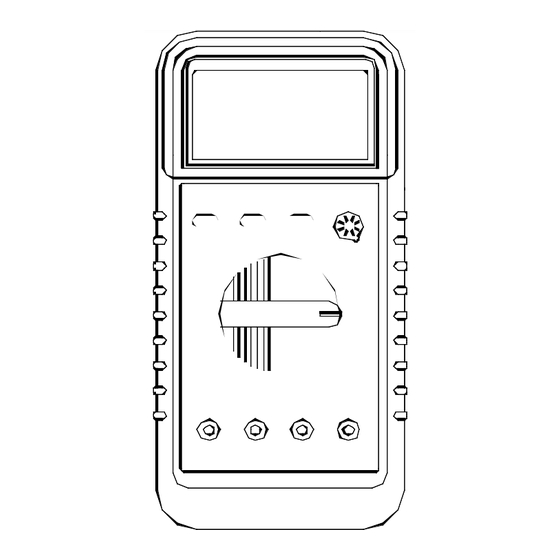
Never use the meter unless the back cover is in place and fastened fully. To clean the meter, use a damp cloth and mild detergent only, do not use abrasives or solvents 2. DESCRIPTION This meter is a portable professional measuring instrument with 3 1/2 digit LCD, capable of performing functions: —... - Page 6 9 mA/Cx input jack 10 10A input jack 2.1 RANGE CONTROL BUTTON Range for AC/DC voltage, AC/DC current (μA and mA only), resistance and frequency measuring can be selected manually or handled by autoranging. Push this button as following to shoose range control mode and desired ranges.
- Page 7 2.2 DATA HOLD BUTTON When this button is pushed, the display will show the last reading and “D-H” symbol will appear until pushing it again. Data holding will be canceled automatically when the function switch is rotated. 2.3 AC/DC CURRENT OR SELECTING Button Push this button to select AC or DC current measuring function when the function switch is set at μA, mA, A...
-
Page 8: Operating Instruction
3. OPERATING INSTRUCTION 3.1 MEASURING VOLTAGE 1. Connect the black test lead to the COM jack and the red test lead to the V/ /F jack. 2. Set the rotary switch at the desired V or V ~ range position and connect test leads across the source or load under measurement. -
Page 9: Measuring Resistance
NOTE: The input voltage should be between 200mV and 10V rms ac. If the voltage is more than 10V rms, reading may be out of the accuracy range. 3.4 MEASURING RESISTANCE 1. Connect the black test lead to the COM jack and the red test lead to the V/ /F jack. -
Page 10: Testing Diode & Continuity
measurement and be sure that the polarity of connection is observed. NOTE: 1. When checking in-circuil capacitance, be sure that the circuit has all power removed and all capacitor are fully discharged. range control mode capacitance measurement is manual ranging and only two ranges (326nF, 32.6μF) are provided. -
Page 11: Testing Transistor
will be displayed. 3.7 TESTING TRANSISTOR 1. Set the rotary switch at hFE position. 2. Identify whether the transistor is NPN or PNP type and locate Emitter, Base and Collector lead. Insert leads of the transistor to be tested into proper holes of the testing socket on the front panel. - Page 12 FUSE PROTECTION: mA: F 300mA/250V A: F 10A/250V POWER SUPPLY: 9V battery, NEDA 1604 or 6F22 DISPLAY: LCD, 3260 counts MAX, updates 2-3/sec MEASURING METHOD: Dual - slope integration A/D converter OVERRANGE INDICATION: “1” figure only on the display POLARITY INDICATION: “—”...
- Page 13 4.3 AC VOLTAGE Range Resolution Accuracy 3.26V 32.6V 10mV ± 0. 8 % of rdg ± 3 digit 326V 100mV 750V Input Impedance: 10M Frequency range: 40 to 400Hz, 40 to 200Hz for 3.26V range. Response: Average, calibrated in rms of sine wave. 4.4 AC CURRENT Range Resolution...
- Page 14 326mA 0.1mA 10mA ± 2.0 % ± 5 0.02V/A Overload protection: F 300mA fuse for A and mA ranges, F 10A fuse for A range. 4.6 CAPACITANCE Range Resolution Accuracy 326nF 0.1nF ± 4.0% of rdg ± 5 digits 32.6μF 10nF 4.7 FREQUENCY Range...
-
Page 15: Accessories
5. ACCESSORIES 5.1 SUPPLIED WITH THE MULTIMETER Test leads Electric Rating 1500V, 10A 1 couple Battery 9V NEDA 1604 or 6F22 1 pcs Operating Manual 1 pcs Holster 1 pcs Capacitance Testing Adapter 1 pcs 5.2 HOW TO USE THE HOLSTER The holster is used to protest the meter and to make the measurement more comfortable, it comes with tow stands installed together. -
Page 16: Battery & Fuse Replacement
6. BATTERY & FUSE REPLACEMENT If the sign appears on the LCD display, it indicates that battery should be replaced. Remove screws on the back cover and open the case. Replace the exhausted battery with a new one. Fuse rarely need replacement and blow almost always as a result of the operator’s error. - Page 17 WARNING Before attempting to open the case, be sure that test leads have been disconnected from measurement circuits to avoid electric shock hazard. For protection against fire, replace fuse only with specified ratings: F1: 200mA/250V (quick acting) - 15 -...
Need help?
Do you have a question about the K8014 and is the answer not in the manual?
Questions and answers