
Related Manuals for RHINO RMCS-2305


Summary of Contents for RHINO RMCS-2305
- Page 1 Dual Channel Optically isolated DC Motor Driver 6V-30V 20Amp RMCS – 2305 Operating Manual v1.0 P a g e https://www.robokits.co.in/...
- Page 2 Contents Introduction – Technical specs ............................ 3 Pin configurationations ............................…..4 Switch Settings of the drive ……............................ 8 Connection Diagram of the drive.........................…..9 Motor control using microcontroller and potentiometer..................…..10 Code for motor control with Arduino.................……………......……..12 Code for speed control from potentiometer..................……………..…...14 P a g e https://www.robokits.co.in/...
-
Page 3: Technical Specifications
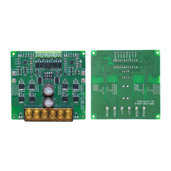
Introduction : The Rhino Dual Driver 20A enables bidirectional control of two high-power brushed DC motors from 6V to 30V. With full discrete NMOS H- Bridge design, this motor driver is able to support 20Amp continuously for each motor without any heat-sink The onboard test buttons and motors output LEDs allow functional test of the motor driver in a quick and convenient way without hooking up the host controller. -
Page 4: Power Led
Pin Configuration of the Drive: Fig 1: Description Description M1A_SW OC2 LED M1B_SW ERR2 LED M2A_SW M1B LED M2B_SW M1A LED POWER LED M2A LED OC1 LED M2B LED ERR1 LED P a g e https://www.robokits.co.in/... - Page 5 NAME FUNCTION Switch to run motor M1 clockwise. (Direction of motor will M1A_SW depend on connection of motor wires) M1B_SW Switch to run motor M1 counter clockwise. Switch to run motor M2 clockwise. (Direction of motor will M2A_SW depend on connection of motor wires) M2B_SW Switch to run motor M2 counter clockwise.
- Page 6 Connection diagram of the Drive: Fig 2 : Description Description SLEEP1 DIR1 VCC (6 – 30 V) OF POWER SUPPLY PWM1 GND OF PWM2 POWER SUPPLY DIR2 SLEEP2 P a g e https://www.robokits.co.in/...
- Page 7 NAME FUNCTION Connect motor M1. Connect motor M1. (Connect in reverse to change direction.) Connect positive of power supply. (6 – 30 V) Connect GND of power supply. Connect motor M2. Connect motor M2. (Connect in reverse to change direction.) Connect to Gnd of microcontroller +5V output.
- Page 8 Switch Settings of the Drive: Fig 3: Peak current Switch S3 Switch s4 Motor M1 60 Amps 40 Amps 16 Amps Peak current Switch S1 Switch S2 Motor M2 60 Amps 40 Amps 16 Amps P a g e https://www.robokits.co.in/...
-
Page 9: Connection Diagram
Connection Diagram Hardware Connection : Fig 4: P a g e https://www.robokits.co.in/... - Page 10 Controlling : As depicted in fig 4 , there is a provision to connect two motors to the driver, with a power supply positioned in between. To initiate a test run of the motors, you can conveniently utilize the push buttons integrated into the driver, specifically M1A_SW and M1B_SW for motor 1, and M2A_SW and M2B_SW for motor 2.
- Page 11 Fig 5: 11 | P a g e https://www.robokits.co.in/...
- Page 12 Sample code for motor control using Arduino : Here you can check this sample code of Arduino to run motor with arduino : /* Connections of RMCS-2305 with arduino : * RMCS2305 : Arduino pins * Sleep1 : 2 * Gnd : gnd...
- Page 13 Fig 6 : 13 | P a g e https://www.robokits.co.in/...
- Page 14 Sample code for speed control using potentiomer : Here you can check this code of Arduino to run motor with potentiomer and Arduino : //Constants: const int PwmPin = 9; //pin 9 has PWM funtion const int potPin = A0; //pin A0 to read analog input //Variables: int value;...
- Page 15 © Rhino Motion Controls, 2023 Neither the whole nor any part of the information contained in, or the product Copyrig described in this manual, may be adapted or reproduced in any material or electronic form without the prior written consent of the copyright holder.
Need help?
Do you have a question about the RMCS-2305 and is the answer not in the manual?
Questions and answers