Table of Contents
Advertisement
Quick Links
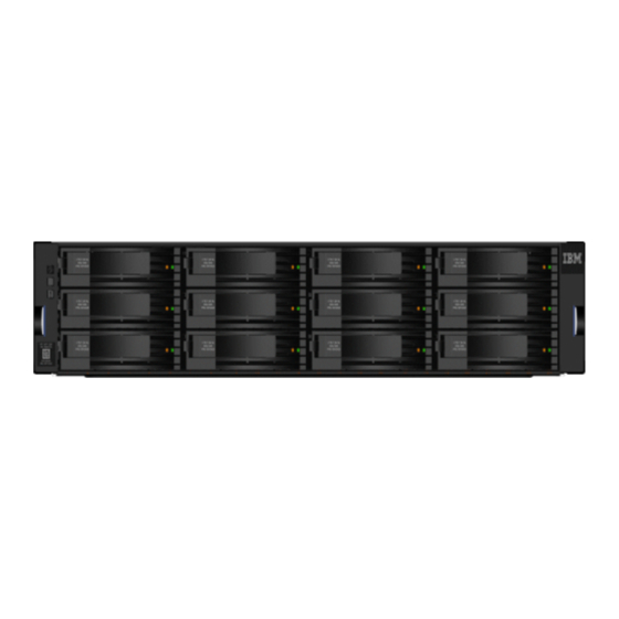
IBM FlashSystem 5000
Control Enclosures
Getting Started Guide
Sign up
If you own an IBM Spectrum
About this task
What you need to know about signing up:
Procedure
1. You need an IBM
ID. Go to
®
2. Register your hardware product.
3. Go to
Subscribe now!
for notification alert.
Overview
This document describes the installation procedures for the following IBM FlashSystem
help you plan the system configuration. This information applies to the following machine type and model (MTM) numbers.
System
Important: This document is intended to be used by persons who are experienced with installing these systems. Before you use this
information and the product it supports, read the following topics:
•
Safety and environmental notices
•
Notices
on page 12
•
IBM Systems Environmental Notices
IBM Documentation (https://ibm.biz/BdqxdY) contains more information about preparing the physical environment before the installation;
it also provides information about configuring, managing, and servicing the system after installation. The IBMDocumentation is updated
between product releases to provide the most current information.
Planning worksheets
Worksheets can help you plan and install the system. Complete the worksheets for each system that you are installing.
Planning Worksheets can be downloaded from
Note: You need to download the pdf on your system to view or download the worksheet.
Virtualize product, you need to sign up to get started.
®
Create your IBM account
IBM FlashSystem 5015 LFF Control Enclosure
IBM FlashSystem 5035 LFF Control Enclosure
IBM FlashSystem 5015 SFF Control Enclosure
IBM FlashSystem 5035 SFF Control Enclosure
on page 11
and
IBM Systems Safety Notices
SSR Install
and complete the form.
(provided on a DVD with your product order)
Worksheet.
control enclosures. It also contains information to
®
MTM
2072-2N2 / 2072-W12
2072-3N2 / 2072-X12
2072-2N4 / 2072-W24
2072-3N4 / 2072-X24
IBM
1
Advertisement
Table of Contents

Related Manuals for IBM FlashSystem 5000


Summary of Contents for IBM FlashSystem 5000
- Page 1 IBM Systems Safety Notices (provided on a DVD with your product order) IBM Documentation (https://ibm.biz/BdqxdY) contains more information about preparing the physical environment before the installation; it also provides information about configuring, managing, and servicing the system after installation. The IBMDocumentation is updated between product releases to provide the most current information.
- Page 2 Network cable connection worksheet Use the following tables to plan and record the cable connections for each control enclosure in your system. Ethernet connections Each node canister in the control enclosure can contain up to six Ethernet ports. Review the following information about the ports. Then, record information about each Ethernet port connection for each node canister in the following table.
- Page 3 Control Enclosure 1: FlashSystem 5015 or the FlashSystem 5035 Left Node Canister 1 Right Node Canister 2 Link Details Port 1 Port 2 Port 3 Port 4 Port 1 Port 2 Port 3 Port 4 Switch Port Speed Control Enclosure 2: the FlashSystem 5035 Left Node Canister 1 Right Node Canister 2 Link Details...
- Page 4 Unpacking and verifying the contents Before you start the installation process, ensure that the following items are available. • Philips screw driver • Box knife • Flat-blade screw driver (optional) • Three Ethernet cables The control enclosure and the following related parts are included in one box. The enclosed inventory sheet lists the part numbers of the items that were ordered.
- Page 5 Mounting holes Bracket pins Round, threaded Unscrew the medium pins and replace them with the smaller pins that are supplied with the rails. Square Unscrew the medium pins and replace them with the large pins that are supplied with the rails. 5.
-
Page 6: Connecting Sas Cables
This task applies if you are installing one or more SAS-attached 2U expansion enclosures to your system. About this task For information about 5U expansion enclosures, see IBM Documentation (https://ibm.biz/BdqxdY) for your product. The following table summarizes the supported SAS chains and enclosures for each system. Follow the guidelines to ensure that your configuration is valid. - Page 7 FlashSystem 5015 the FlashSystem 5035 Connect networking cables To provide connectivity for the system, you must connect networking cables to the appropriate ports on the control enclosure. Ethernet ports on each node canister provide system management connections and iSCSI host connectivity. The onboard 10 Gbps Ethernet ports use RJ-45 connections.
- Page 8 Port Type Function 12 Gb SAS ports 1 and 2 SAS Expansion only (arrow that points away from the port indicates expansion). Connecting Ethernet cables 1. Connect Ethernet port 1 of each node canister to the IP network that provides the connection to the system management interfaces. FlashSystem 5015 the FlashSystem 5035 Ethernet port 1 can be used for iSCSI connectivity to the system by hosts on the network.
-
Page 9: Powering On The System
Powering on the system After you install all hardware components, you must power on the system and check its status. Each control enclosure has two power supply units (PSUs). To provide redundancy in a power failure, connect the power cords to separate power circuits. Attention: Do not power on the system with any open drive bays or host interface adapter slots. - Page 10 Static IPv4 Address Subnet Mask Gateway 192.168.0.2 255.255.255.0 192.168.0.1 192.168.0.1 2. Locate the Ethernet port that is labeled T on the rear of the node canister. On FlashSystem 5015 systems, Ethernet port 2 also serves as the technician port. the FlashSystem 5035 systems have a dedicated technician port. Table 1: Location of the technician port on a node canister FlashSystem 5015 the FlashSystem 5035...
-
Page 11: Browser Considerations
2. Locate the IBM Systems Safety Notices document with the user publications that were provided with your system hardware. 3. Find the matching identification number in IBM Systems Safety Notices. Then, review the topics about the safety notices to ensure that you are in compliance. -
Page 12: Compliance Standards
IBM may not offer the products, services, or features discussed in this document in other countries. Consult your local IBM representative for information on the products and services currently available in your area. Any reference to an IBM product, program, or service is not intended to state or imply that only that IBM product, program, or service may be used. -
Page 13: Homologation Statement
The licensed program described in this document and all licensed material available for it are provided by IBM under terms of the IBM Customer Agreement, IBM International Program License Agreement or any equivalent agreement between us. The performance data discussed herein is presented as derived under specific operating conditions. Actual results may vary. - Page 14 Um dieses sicherzustellen, sind die Geräte wie in den Handbüchern beschrieben zu installieren und zu betreiben. Des Weiteren dürfen auch nur von der IBM empfohlene Kabel angeschlossen werden. IBM übernimmt keine Verantwortung für die Einhaltung der Schutzanforderungen, wenn das Produkt ohne Zustimmung von IBM verändert bzw. wenn Erweiterungskomponenten von Fremdherstellern ohne Empfehlung von IBM gesteckt/eingebaut werden.
- Page 15 This statement applies to products greater than 20 A, single phase. This statement applies to products greater than 20 A per phase, three-phase. Japan Voluntary Control Council for Interference (VCCI) Notice Korea Notice People's Republic of China Notice 警告:在居住环境中,运行此设备可能会造成无线电干扰。 Russia Notice Taiwan Notice CNS 13438 警告使用者...
- Page 16 Properly shielded and grounded cables and connectors must be used in order to meet FCC emission limits. IBM is not responsible for any radio or television interference caused by using other than recommended cables and connectors, or by unauthorized changes or modifications to this equipment.
- Page 17 Um dieses sicherzustellen, sind die Geräte wie in den Handbüchern beschrieben zu installieren und zu betreiben. Des Weiteren dürfen auch nur von der IBM empfohlene Kabel angeschlossen werden. IBM übernimmt keine Verantwortung für die Einhaltung der Schutzanforderungen, wenn das Produkt ohne Zustimmung von IBM verändert bzw. wenn Erweiterungskomponenten von Fremdherstellern ohne Empfehlung von IBM gesteckt/eingebaut werden.
- Page 18 These statements apply to products greater than 20 A, single phase. This statement applies to products greater than 20 A per phase, three-phase. Japan Voluntary Control Council for Interference (VCCI) Notice Taiwan Notice IBM Taiwan Contact Information:...
-
Page 19: For Your Reference
Properly shielded and grounded cables and connectors must be used in order to meet FCC emission limits. Proper cables and connectors are available from IBM-authorized dealers. IBM is not responsible for any radio or television interference caused by using other than recommended cables and connectors or by unauthorized changes or modifications to this equipment.
Need help?
Do you have a question about the FlashSystem 5000 and is the answer not in the manual?
Questions and answers