Table of Contents
Advertisement
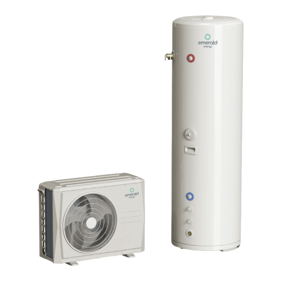
REFRIGERANT CYCLING HEAT PUMP WATER HEATER
USER MANUAL
MODEL NUMBERS:
Residential:
EE-HWS-RCHPOU/EE-HWS-RCHP-200
EE-HWS-RCHPOU/EE-HWS-RCHP-200E
EE-HWS-RCHPOU/EE-HWS-RCHP-300
EE-HWS-RCHPOU/EE-HWS-RCHP-300E
CONTENTS
Commercial:
EE-HWS-RCHPOU/EE-HWS-RCHP-200-1
EE-HWS-RCHPOU/EE-HWS-RCHP-200E-1
EE-HWS-RCHPOU/EE-HWS-RCHP-300-1
EE-HWS-RCHPOU/EE-HWS-RCHP-300E-1
2-4
5-6
5
5
6
7-8
7
8
9-14
9
10
11
13
14
15-17
15
16
16
17
18
Thank you for choosing Emerald Energy.
19
This leaflet contains important information on the correct
20-21
installation and operation of your heat pump water heater.
20
20
20
POWER SUPPLY:
20
ENVIRONMENT TEMPERATURE:
21
Working water temperature: Min inlet water temperature 5°C,
22
Max outlet Water Temperature 60°C.
220V-240V/1N~50Hz
-15°C - 46°C
Advertisement
Table of Contents

Related Manuals for Emerald EE-HWS-RCHPOU


Summary of Contents for Emerald EE-HWS-RCHPOU
-
Page 1: Table Of Contents
- Power supply cords - Water tank temperature sensor installation - ODX & AUX power connection - Dial code definitions CHECK Thank you for choosing Emerald Energy. OPERATION AND PERFORMANCES This leaflet contains important information on the correct MAINTENANCE 20-21 installation and operation of your heat pump water heater. -
Page 2: Safety Precautions
Continuous leakage of water from the valve may indicate a problem with the • Contact Emerald for any further assistance. water heater. If the hot water system is not used for two weeks or more, a quantity of highly flammable hydrogen gas may accumulate in the water heater. - Page 3 1. SAFETY PRECAUTIONS Do not remove, cover, or obscure any permanent instructions, labels, Servicing shall only be performed as recommended by the or data labels located on the exterior or interior of the unit. equipment manufacturer. Maintenance and repair requiring the assistance of other skilled personnel shall be carried out under Only a qualified person should perform relocation, repair, and the supervision of the person competent in the use of flammable...
- Page 4 1. SAFETY PRECAUTIONS ⚠ CAUTION This appliance can be used by children 8 years old and above and persons with reduced physical, sensory or mental capabilities or lack of experience and knowledge if they are supervised or given Generally, the ambient air temperature of the unit must be above instruction on using the unit in a safe manner and understand the -15°C and below 43°C.
-
Page 5: General Introduction
2. GENERAL INTRODUCTION 2.1 OUTDOOR UNIT NAME Power cord enclosure High pressure valve Low pressure valve Air outlet Air inlet Fig. 2-1 2.2 WATER TANK NAME Magnesium rod insertion port Foam filling port Reserved port Water outlet Temperature pressure safety valve Water tank temperature sensor Handle Refrigerant gas pipe... -
Page 6: Specifications
2. GENERAL INTRODUCTION 2.3 SPECIFICATIONS EE-HWS-RCHP-200 EE-HWS-RCHP-200E EE-HWS-RCHP-300 EE-HWS-RCHP-300E MODEL NUMBER EE-HWS-RCHP-200-1 EE-HWS-RCHP-200E-1 EE-HWS-RCHP-300-1 EE-HWS-RCHP-300E-1 Ambient temperature ºC -15~46 Leaving water temperature ºC 20~63 Capacity 2600 Heating Input 1000 STC values 33(Zone3) / 36(Zone4) 33(Zone3) / 36(Zone4) 32(Zone3) / 35(Zone4) 32(Zone3) / 35(Zone4) GENERAL Hot water yield 0.044... -
Page 7: Before Installation
3. BEFORE INSTALLATION 3.1 ACCESSORIES Flexible hose (pair) 2 x 2.5m refrigerant piping (6.35mm & Single bend copper tails and 9.52mm) lagging c/w 15mm connections 2 x Connector Tempering valve c/w cover (15 male*15 screw) TPR valve fitting 15mm 1 x 15mm copper straights 3 x 15mm copper bends Electrical circuit breaker, 20A ELECTRICAL... -
Page 8: Space For Maintenance
3. BEFORE INSTALLATION 3.2 SPACE FOR MAINTENANCE NOTE It is necessary to reserve enough installation and maintenance space during installation according to the following figures. 3.2.1 OUTDOOR UNIT INSTALLATION AND MAINTENANCE SPACE. ≥600mm Use bolt to fix Air outlet Fig. 3-1 Fig. -
Page 9: Installation Procedure
4. INSTALLATION PROCEDURE NOTE This heat pump unit must be installed, repaired or moved only by an authorised installer or technician. When installing the heat pump, it is important to locate it in an area that is not exposed to direct sunlight or other sources of heat. If this is not possible, a cover should be added to protect the unit from direct sunlight. -
Page 10: Drain Hole Position
4. INSTALLATION PROCEDURE 4.1.2 WATER TANK. DIMENSION MODEL 200L 1665 300L 1735 Table 4-2 Fig. 4-4 Fig. 4-5 Please install the water tank fixing strip as shown in the figure to ensure that the water tank is stably fixed. 4.2 DRAIN HOLE POSITION Water outlet connection pipe/gasket... -
Page 11: Pipe Connection
4. INSTALLATION PROCEDURE 4.3 PIPE CONNECTION 4.3.1 UNIT CONNECTION SKETCH Hot water outlet GUTTERS 9.52 6.35 Cold water inlet OUTDOOR UNIT WATER TANK Fig. 4-8 GUTTERS NAME Water end user Stop valve Water mixing valve ICON Safety valve NAME Gutter (if required) ICON Table 4-2... - Page 12 4. INSTALLATION PROCEDURE 4.3 PIPE CONNECTION (CONTINUED) ⚠ CAUTION Before water heater runs, please make sure every stop valve 4.3.2 PTR VALVE has been opened. The valve body unloading pressure is 850kPa, unloading tempera- ture is 99ºC, and the valve body opening energy value is 46kW, for 4.3.3 CONNECTION LENGTH OF OUTDOOR UNIT AND WATER more details refer to certificate No:WMK26608.
-
Page 13: Vacuum Drying
4. INSTALLATION PROCEDURE 4.4 VACUUM DRYING 4.4.1 PURPOSE Vacuum drying should be performed in order to remove moisture and non-condensible gases from the system. Removing moisture prevents ice formation and oxidization of copper piping or other internal components. The presence of ice particles in the system would cause abnormal operation, whilst particles of oxidized copper can cause compressor damage. -
Page 14: Refrigerant Charge
4. INSTALLATION PROCEDURE ITEM DESCRIPTION IMAGE NOTE Connect the (low pressure side) Before performing vacuum drying, make sure that all hose of a pressure gauge to the the outdoor unit stop valves are firmly closed. outdoor unit gas pipe stop valve. 1. -
Page 15: Electrical Connection
5. ELECTRICAL CONNECTION ⚠ CAUTION The heat pump must have a separate power supply with the correct rated voltage. The external power supply to the heat pump should have ground wiring, which is linked to the ground wiring of the indoor and outdoor unit. The wiring work should be done by qualified persons according to circuit drawing. -
Page 16: Water Tank Temperature Sensor Installation
5. ELECTRICAL CONNECTION 5.2 WATER TANK TEMPERATURE SENSOR INSTALLATION Connect the water tank temperature sensor wire connector to the outdoor unit T5L connector. Water tank temperature sensor T5L Fig. 5-1 5.3 ODU & AUX. POWER CONNECTION NOTE If the water tank has the electric auxiliary heating (AUX.) function, please follow the steps below to connect the electric auxiliary heating power cord. -
Page 17: Dial Code Definitions
5. ELECTRICAL CONNECTION 3.Outdoor unit power supply. o o o C: E-heater power cord 1 : Electric counter Power supply E-heater 2 : Global over current and leakage circuit breaker Terminal block Fig. 5-5 3 : Electric leakage circuit breaker 4 : over current circuit breaker ⚠... -
Page 18: Check
6. CHECK NOTE Before switching on the unit, read following recommendations: When the installation and parameter setting are completed, cover all the sheet metal of the unit well. The unit should be maintained by professionals. If the unit has failed or is in protection mode, the panel will show the relevant code. If multiple failures or protection modes occur, they will be displayed in the order they happened. -
Page 19: Operation And Performances
7. OPERATIONS AND PERFORMANCES ⚠ CAUTION Cut off manual switch power when the unit fails. Do not restart until the issues have been resolved. 1. Characteristics of water heating - 3 minute protection When restarting the unit after a short shutdown, there will be a 3 minute delay before it begins operation due to the self-protect function of the compressor. -
Page 20: Maintenance
8. MAINTENANCE 8.1 CONFIRMATION BEFORE RUNNING 8.3 AFTER SALES SERVICE 1. Make sure the wires are grounded In case of malfunctions, please cut off the power switch and contact after-sales service centre or technical service department, for de- 2. Turn on power supply switch for 12 hours before running. tailed information please refer to User Service Guide. -
Page 21: Water Quality Limitation
8. MAINTENANCE 8.5 WATER QUALITY LIMITATIONS NOTE If the water quality does not meet the requirements in the table below, please contact the supplier for advice. Electrical PH Value Total Hardness Conductivity 6.5-8.0 50ppm <200μS/cm(25ºC) Sulphate Ion Silicon Iron Content <50ppm <30ppm <0.3ppm... -
Page 22: Error Code Table
TROUBLE SHOOTING ERROR CAUSE CODE Communication error Water tank temperature sensor error (T5L) ODU heat exchanger temperature sensor error (T3) ODU ambient temperature sensor error (T4) Suction temperature sensor error (Th) Discharge temperature sensor error (Tp) Clock chip error Smart Grid signal error E-heater error (Current is less than 2A when e-heater operating) High pressure protection... - Page 24 Emerald Energy Pty Ltd warrants this heat pump to the original purchaser. Emerald Energy Pty Ltd warrants each new heat pump is free from defects in material and workmanship under normal use and service from the date of purchase. 2 year labour warranty. 7 years warranty on the tank, and 5 years on the rest of the system. *Subject to terms and conditions.
Need help?
Do you have a question about the EE-HWS-RCHPOU and is the answer not in the manual?
Questions and answers