Table of Contents
Advertisement
Quick Links
REFRIGERANT CYCLING HEAT PUMP WATER HEATER
USER MANUAL
MODEL NUMBERS:
EE-HWS-RCHP-200 EE-HWS-RCHP-200E
EE-HWS-RCHP-300 EE-HWS-RCHP-300E
Thank you for choosing Emerald Energy.
This leaflet contains important information on the correct
installation and operation of your heat pump water heater.
CONTENTS
2-3
4
SAFETY INFORMATION
4
4
Read these instructions carefully before installation.
Keep this manual in a handy for future reference.
5
5
Improper installation of equipment or accessories may
5
result in electric shock, short-circuit, leakage, fire or
other damage to the equipment. Be sure to only use
6-9
accessories made by the supplier, which are specifically
6
designed for the equipment and make sure to get
7
installation done by a professional.
7
All the activities described in this manual must be carried
8
out by a licensed technician. Be sure to wear adequate
9
personal protection equipment while installing the unit
10-12
or carrying out maintenance activities.
10
Contact your dealer for any further assistance.
11
11
12
13
14
15
15
15
POWER SUPPLY:
15
ENVIRONMENT TEMPERATURE:
15
Working water temperature: Min inlet water temperature 5°C,
16
Max outlet Water Temperature 60°C.
220V-240V/1N~50Hz
-15°C - 46°C
Advertisement
Table of Contents

Related Manuals for Emerald EE-HWS-RCHP-200


Summary of Contents for Emerald EE-HWS-RCHP-200
-
Page 1: Table Of Contents
REFRIGERANT CYCLING HEAT PUMP WATER HEATER USER MANUAL MODEL NUMBERS: EE-HWS-RCHP-200 EE-HWS-RCHP-200E EE-HWS-RCHP-300 EE-HWS-RCHP-300E Thank you for choosing Emerald Energy. This leaflet contains important information on the correct installation and operation of your heat pump water heater. CONTENTS SAFETY PRECAUTIONS... -
Page 2: Safety Precautions
1. SAFETY PRECAUTIONS The precautions listed here are divided into the following types. Electric connection work should obey the instructions of local power company, local electric utility and this manual. They are important, please follow them carefully. Never use the wiring and fuse with wrong rated current, otherwise the unit maybe break down and cause fire further more. - Page 3 1. SAFETY PRECAUTIONS ⚠ CAUTION Children should be supervised to ensure that they do not play with the appliance. The earthing pole of socket must be grounded well, make sure that If the supply cord is damaged, it must be replaced by the manufactur- power supply socket and plug are dry enough and connected tightly.
-
Page 4: General Introduction
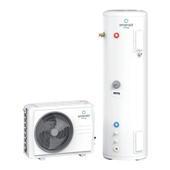
2. GENERAL INTRODUCTION 2.1 OUTDOOR UNIT NAME Power cord enter High pressure valve Low pressure valve Air outlet Air inlet Fig. 2-1 2.2 WATER TANK NAME Magnesium rod insertion port Foam filling port Reserved port Water outlet Temperature pressure safety valve Water tank temperature sensor Handle Refrigerant gas pipe... -
Page 5: Before Installation
3. BEFORE INSTALLATION 3.1 ACCESSORIES ACCESSORY NAME SHAPE PURPOSE Installation manual Need by master unit Wired controller components Control unit and display unit status Water drainage connection For condensate water draining Water temperature sensor Measure water temperature inside water tank Water drainage pipe Condensate water drainage of unit bottom plate Plastic expansion tube... -
Page 6: Installation Procedure
4. INSTALLATION PROCEDURE NOTE Ask your dealer or specialized person for moving, repair, and maintenance. Install it in the place without direct sunlight and other direct heat radiations. If it can’t be avoided, please add a cover to prevent unit from direct sunlight. -
Page 7: Drain Hole Position
4. INSTALLATION PROCEDURE 4.2 DRAIN HOLE POSITION Water outlet connection pipe/gasket Fig. 4-3 4.3 PIPE CONNECTION 4.3.1 UNIT CONNECTION SKETCH Unit connection sketch, please refer to Fig.4-4. Hot water outlet 9.52 6.35 Cold water inlet Fig. 4-4 OUTDOOR UNIT WATER TANK Stop valve Water mixing valve NAME... -
Page 8: Vacuum Drying
4. INSTALLATION PROCEDURE 4.3 PIPE CONNECTION (CONTINUED) 4.4 VACUUM DRYING 4.3.2 STOP VALVE INSTRUCTION 4.4.1 PURPOSE In general, the shape of stop valve and names of each part are Vacuum drying should be performed in order to remove moisture and non-condensible gases from the system. Removing moisture shown in Fig.4-5. -
Page 9: Refrigerant Charge
4. INSTALLATION PROCEDURE ITEM DESCRIPTION IMAGE NOTE Connect the blue (low pressure side) Before performing vacuum drying, make sure that all hose of a pressure gauge to the outdoor the outdoor unit stop valves are firmly closed. unit gas pipe stop valve. 1. -
Page 10: Electrical Connection
5. ELECTRICAL CONNECTION ⚠ CAUTION The heat pump should use separate power supply with rated voltage. If voltage is not stable, please use stabilized voltage supply. The external power supply to the heat pump should have ground wiring, which is linked to the ground wiring of the indoor and outdoor unit. The wiring work should be done by qualified persons according to circuit drawing. -
Page 11: Electrical Wiring Diagram
5. ELECTRICAL CONNECTION 5.2 ELECTRICAL WIRING DIAGRAM (SEE FIG 5-2) Fig. 5-1 5.3 WATER TANK TEMPERATURE SENSOR INSTALLATION Connect the water tank temperature sensor wire connector to the outdoor unit T5L connector. Fig. 5-2... -
Page 12: Odx & Aux Power Connection
5. ELECTRICAL CONNECTION 5.4 ODU & AUX. POWER CONNECTION NOTE If the water tank has the electric auxiliary heating( AUX.) function, please follow the steps below to connect the electric auxiliary heating power cord. 1. Remove the protective cover of the electric control box on the right side of the outdoor unit. -
Page 13: Check
6. CHECK NOTE Before switching on the unit, read following recommendations: When the installation and parameter setting are completed, cover all the sheet metal of the unit well. The unit should be maintained by professionals. If the whole unit failed or in protection, the panel will display the corresponding code; when more than one failure or protection occurs, the order of failure protection will display. -
Page 14: Operation And Performances
7. OPERATIONS AND PERFORMANCES ⚠ CAUTION Please cut off the manual switch power when unit fails. Do not restart until problems are solved. 1. Characteristics of water heating - 3 minute protection. Restart or open manual switch after the unit has been shut down. Unit will not start immediately until 3 minutes later, because of the self-protect function of the compressor. -
Page 15: Maintenance
8. MAINTENANCE 8.1 CONFIRMATION BEFORE RUNNING 8.3 AFTER-SALE SERVICE 1) Make sure whether ground wire is broken or fall off. In case of following malfunctions, please cut off the power switch and contact after-sale service centre or technical service department, for 2) Turn on power supply switch for 12 hours before running. -
Page 16: Error Code Table
Emerald Energy Pty Ltd warrants this heat pump to the original purchaser. Emerald Energy Pty Ltd warrants each new heat pump is free from defects in material and workmanship under normal use and service from the date of purchase. 2 year labour warranty. 7 years warranty on the tank, and 5 years on the rest of the system. *Subject to terms and conditions.
Need help?
Do you have a question about the EE-HWS-RCHP-200 and is the answer not in the manual?
Questions and answers